1998 HONDA CIVIC air mix
[x] Cancel search: air mixPage 1469 of 2189
A/C System Service
Evacuation
Use only service equipment that is U L.-listed and is cer-
tified to meet the requirements oJ SAE J2210 to remove
HFC-134a (R-134a) from the air conditioner system'
CAUTION: Exposure to air conditioner reftig€lant and
lubricant vapor or misi can irrhaie eyes. noso and throat'
Avoid breathing the ail condhioner lefrigelant and lubri
cant vapor or mist.
lf accidental system discharge occurs, ventilate work
area before resuming servace.
R-134a service equipment or vehicle air conditioner sys-
tems should not be pressure tested or leak tested with
comDressed air.
!!@@ some mixtures of air and R-13'[8 haYo boon
ffiiE-n to be "ombustible at elovatod pressurcs and can
result in fire or explosion causing iniury or propsrtY
damag€. Never uso complsssod air to pre3surs tost R-
1344 ssrvico equipment or vehicle air conditioner sy3-
tems,
Additional health and safety information may be obtained
from the refrigerant and lubricant manuJacturers'
When an A,/C System has been opened to the atmo-
sphere, such as during installation or repair, it must
be evacuated using a R-134a refrigerant recovery/
recycling/charging station. (lf the system has been
open for several days, the receiver/dryer should be
replaced, and the system should be evacuated for
several hours.)
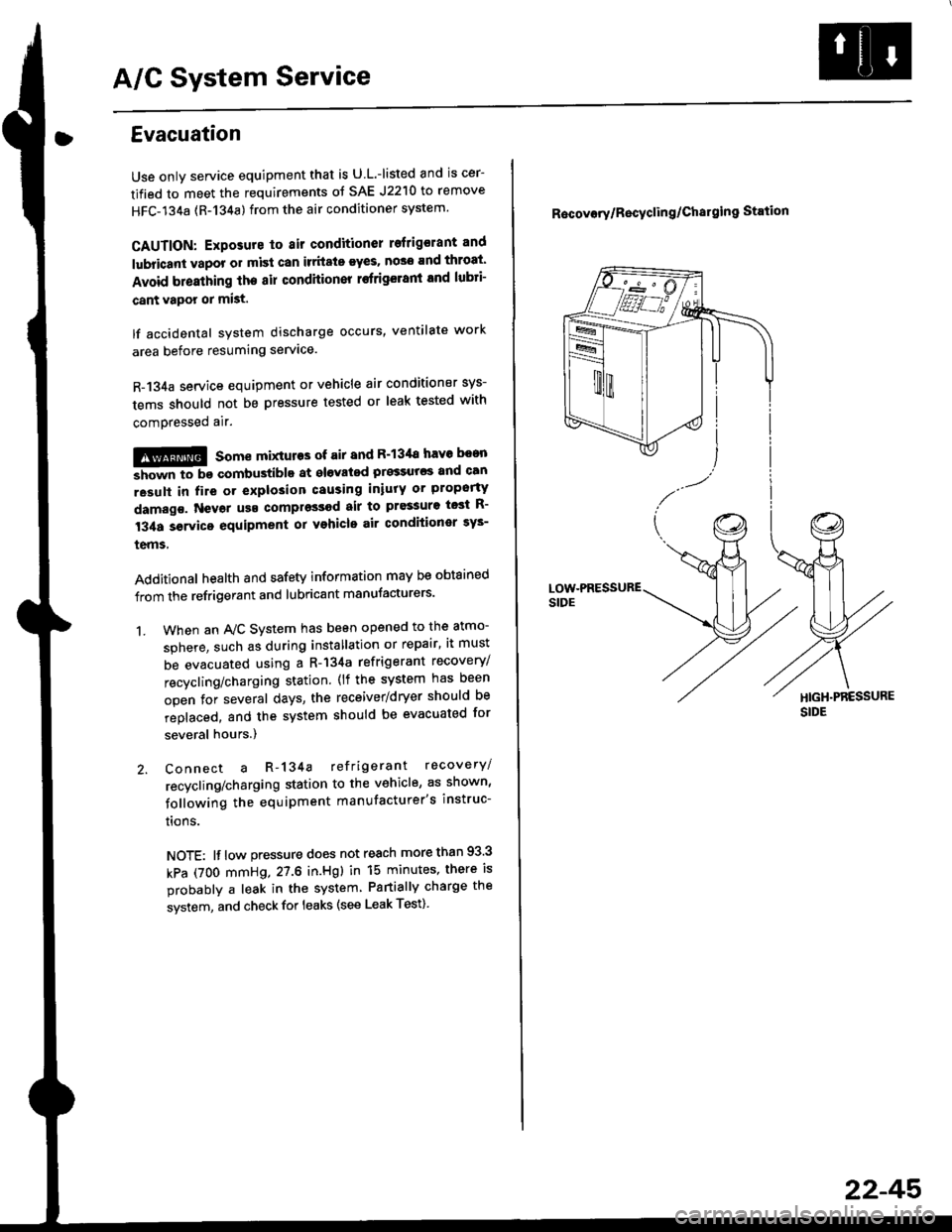
Connect a R-134a refrigerant recovery/
recycling/charging station to the vehicle, as shown'
following the equipment manufacturer's instruc-
trons.
NOTE: lf low pressure does not reach more than 93 3
kPa (7OO mmHg,27.6 in.Hgl in 15 minutes, there is
probably a leak in the system Partially charge the
system, and check for leaks (see Leak Test)
1.
R6covory/Recyclin g/Chal9ing Station
22-45'
Page 1470 of 2189
A/C System Service
Charging
Use only service equipment that is U.L.-listed and is cer-
tified to meet the requirements of SAE J2210 to remove
HFC-134a (R-134a) from the air conditioner system.
CAUTION: Exposure to air conditioner refrigerant and
lubricant vapor or mist can irritale eyes, nose and
throat. Avoid breathing the air conditioner retrigerant
and lubricant vaoor or mist,
lf accidental system discharge occurs, ventilate workarea before resuming service, Additional health and
safety information may be obtained from the refrigerant
and lubricant manufacturers.
Refrigerant capacityt 600 - 650 g 121.1 - 22.9 ozl
CAUnON: Do not overcharg€ the system; the comprcssor
will be damaged.
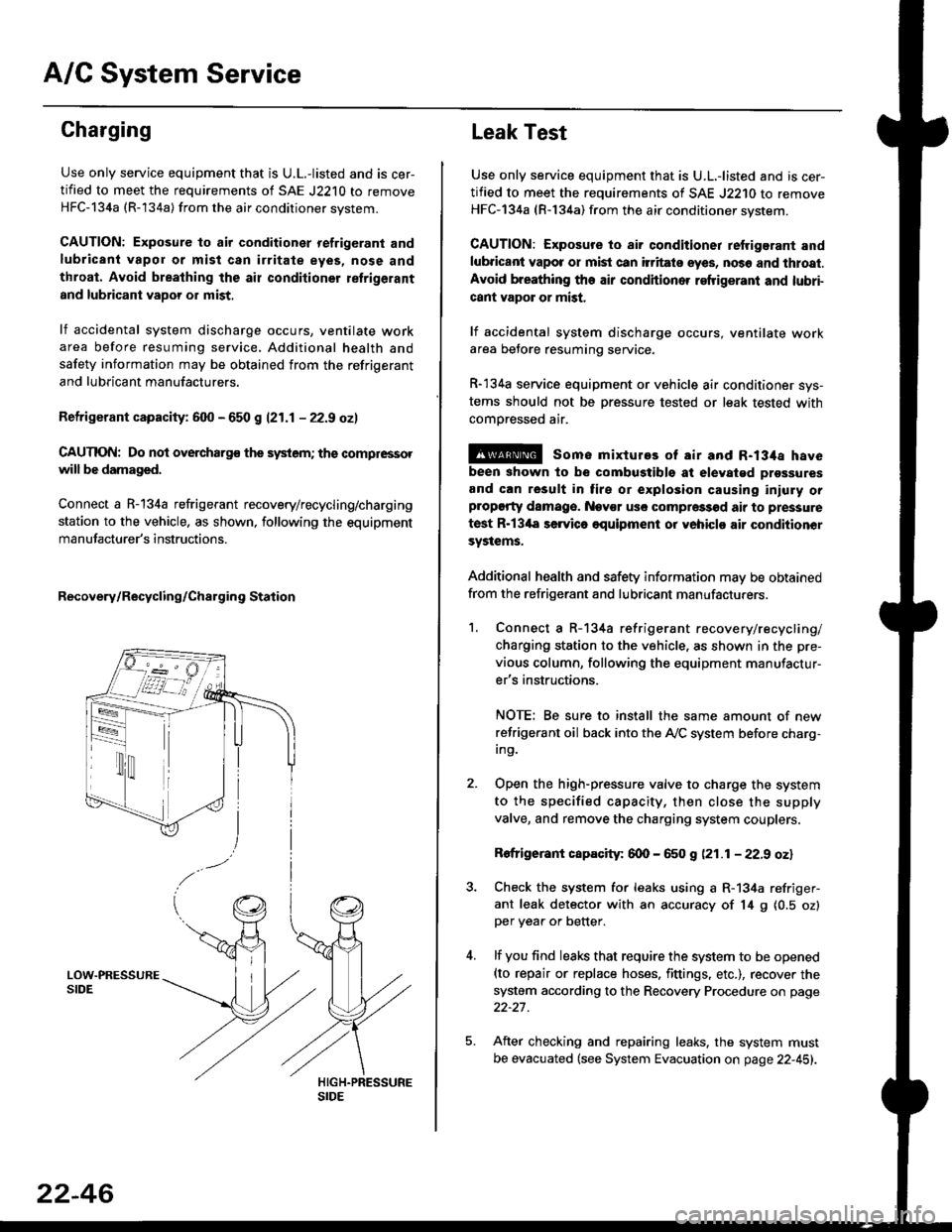
Connect a R-134a refrigerant recovery/recycling/charging
station to the vehicle, as shown, following the equipment
manufacturer's instructions.
Recovery/Recycling/Charging Station
22-46
Leak Test
Use only service equipment that is U.L,-listed and is cer-
tified to meet the requirements of SAE J2210 to remove
HFC-134a (R-134a) from the air conditioner system.
CAUTION: Exposure io air conditioner refrigerant and
lubricant vapot or mist can itritats eyes, no36 and thtoat.
Avoid breathing the air conditioner refrigeranl and lubri-
cant vapor or mist,
lf accidental system discharge occurs, ventilate workarea betore resuming service.
R-134a service equipment or vehicle air conditioner sys-
tems should not be pressure tested or leak tested with
comoressed air.
@ some mixtures of air and R-134a have
been shown to be combugtibls at elevatgd prossures
and can result in tire or explosion causing iniuly orplopgrty damage. Nev€r usc compre33od air to pressure
test R-13'la servica oquipment or yohiclo air conditionor
systems.
Additional health and safety information may be obtained
from the refrigerant and lubricant manufacturers.
1. Connect a R-134a refrigerant recove rylrecycling/
charging station to the vehicle, as shown in the pre-
vious column, following the equipment manufactur-
er's instructions.
NOTE; Be sure to install the same amount of new
refrigerant oil back into the A,/C system before charg-In9.
Open the high-pressure valve to charge the system
to the specified capacity, then close the supply
valve, and remove the charging system couplers.
Rofrigerant capacity: 600 - 650 g (21.1 - 22.9 oz)
Check the system for leaks using a R-134a refriger-
ant leak detector with an accuracy of 14 9 10.5 ozlper yea. or better.
lf you find leaks that require the system to be opened(to repair or replace hoses. fittings. etc.), recover the
system according to the Recovery Procedure on page
22-27.
After checking and repairing leaks. the system must
be evacuated (see System Evacuation on page 22-451.
Page 1529 of 2189
'
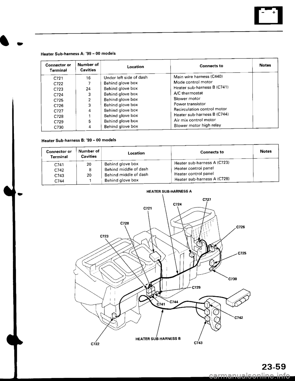
Heater Sub-harness A: '99 - 00 models
Connector or
Terminal
Number of
CavitiesLocationConnects toNotes
c721
c722
c723
c724
c725
c726
c727
c728
c729
c730
7
24
3
2
4
1
5
4
Under left side of dash
Behind glove box
Behind glove box
Behind glove box
Behind glove box
Behind glove box
Behind glove box
Behind glove box
Behind glove box
Behind glove box
Main wire harness (C440)
Mode control motor
Heater sub-harness B (C741)
lilc thermostat
Blower motor
Power transistor
Recircuiation control motor
Heater sub-harness B (C744)
Air mix control motor
Blower motor high relaY
Heater Sub-harness B: '99 - 00 models
HEATER SUB.HARNESS A
Connector or
Terminal
Number of
CavitiesLocationConnects toNotes
c7 41
c'742
c143
c744
20
8
20
1
Behind glove box
Behind middie of dash
Behind middle of dash
Behind glove box
Heater sub-harness A (C723)
Heater control Panel
Heater control Panel
Heater sub-harness A (C728)
Page 1664 of 2189
Stereo Sound System
Window Antenna Wire Test
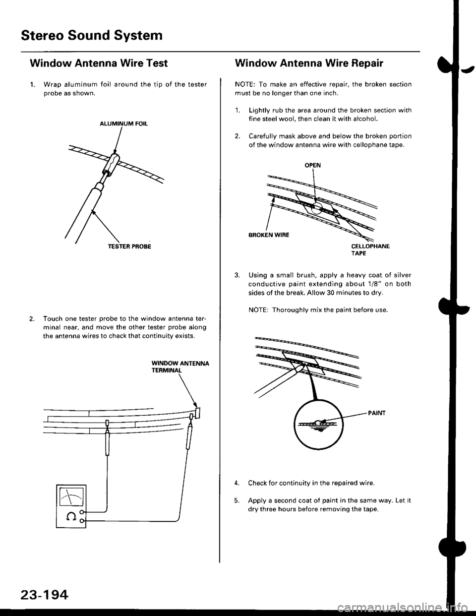
1. Wrap aluminum foil around the tip of the tester
probe as shown.
Touch one tester orobe to the window antenna ter-
minal near, and move the other tester probe along
the antenna wires to check that continuity exists.
WINDOW ANTENNA
23-194
OPEN
Window Antenna Wire Repair
NOTE: To make an effective repair, the broken section
must be no longer than one inch.
1. Lightly rub the area around the broken section with
fine steel wool, then clean it with alcohol.
2. Carefully mask above and below the broken portion
of the window antenna wire with cellophane tape.
CELLOPHANETAPE
Using a small brush, apply a heavy coat of silver
conductive paint extending about 1/8" on both
sides of the break, Allow 30 minutes to dry.
NOTE| Thoroughly mix the paint betore use.
Check for continuity in the repaired wire.
Apply a second coat of paint in the same way. Let it
dry three hours before removing the tape.
Page 1674 of 2189
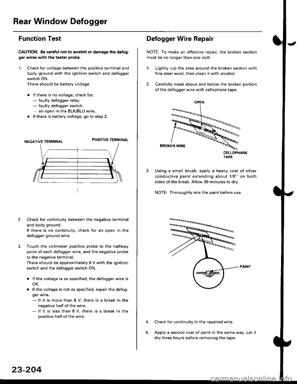
Rear Window Defogger
Function Test
CAUTION: Bs careful nol to scralch or damage the defog-
ger wires with the tester probe,
'1. Check for voltage between the positive terminal and
body ground with the ignition switch and defogger
switch ON.
There should be banery voltage.
. lf there is no voltage, check for:- faulty defogger relay.- faulty defogger switch.
an ooen in the BLK,/BLU wire.
. lf there is battery voltage, go to step 2.
POSITIVE TERMINAL
2. Check for continuity between the negative terminal
and body ground.
lf there is no continuity, check for an open in the
defogger ground wire.
Touch the voltmeter positive probe to the halfway
point of each defogger wire, and the negative probe
to the negative terminal.
There should be approximately 6 V with the ignition
switch and the defogger switch ON.
. lf the voltage is as specified. the defogger wire is
oK.
. lf thevoltage is not as specified, repairthe defog-
ger wrre.- lf it is more than 6 V, there is
negative half of the wire.- lf it is less than 6 V, there is
positive half of the wire.
a break in the
a break in the
23-204
OPEN
?
Defogger Wire Repair
NOTE: To make an effective repair, the broken section
must be no longer than one inch.
1, Lightly rub the area around the broken section with
fine steel wool, then clean it with alcohol.
2. Carefully mask above and below the broken portion
of the defogger wire with cellophane tape.
CELLOPHANETAPE
Using a small brush, apply a heavy coat of silver
conductive paint extending about 1/8" on both
sides of the break. Allow 30 minutes to dry.
NOTE: Thoroughly mix the paint before use.
Check for continuity in the repaired wire.
Apply a second coat of paint in the same way. Let it
dry three hours before removing the tape.
Page 1952 of 2189
![HONDA CIVIC 1998 6.G Workshop Manual Air Delivery
- 99-00 Models
a
r--T----.I UNDER-HOOD UNDEB-DASH
| ,ry:i.l? IFUSE/RELAY I t::u:E^tt l:usE/RELAyi
- -{-;;; -
I PJ,.,8.J390 i
-
T;; ;
- - - - -
I H$3,,8
i 1;:t"* ];FPJ", i i m. HONDA CIVIC 1998 6.G Workshop Manual Air Delivery
- 99-00 Models
a
r--T----.I UNDER-HOOD UNDEB-DASH
| ,ry:i.l? IFUSE/RELAY I t::u:E^tt l:usE/RELAyi
- -{-;;; -
I PJ,.,8.J390 i
-
T;; ;
- - - - -
I H$3,,8
i 1;:t"* ];FPJ", i i m.](/manual-img/13/6068/w960_6068-1951.png)
Air Delivery
- '99-'00 Models
a
r--T----.I UNDER-HOOD UNDEB-DASH
| ,ry:i.l? IFUSE/RELAY I t::u:E^tt l:usE/RELAyi
- -{-;;; -
I PJ,'.',8.J390 i
-
T;; ;
- - - - -
I H$3,',8
i 1;:t"* ];FPJ", i i m'.u" se€power i "t8L,,
i t i a l'"0 r3l",lli"i:" aL--{..-----J L-J..----5::---:-J
"",":"rfi?ll, '[r;T:1"
-",*"1-J
*-*..l
,n", ".u I lt I
lr !I See Power I See Power Distnbution.I Distribution, U page 1o-9.
,, L::':l------- *Y=l
"*o "."",,t
[
*,:.'.Y%
Irel-
lt
:'l-4riffi
MODECONTROLMOTOR
;L:L{;I{,tt't{ {f
SensorGround grgund
venl
Air mix5Y poientia,reTgrano9 rnrrul
gIouno
RecircSwilcfi switchcommon mput
Recirc S$,itchtED LEDcontrol common
RECIRCULATIONCONTROLMOTORPHOTO 139
CONTROLPANEL
vtEw 76
So€ Roar II Windolv :
a
Htr Ttr =tr ;l *tr :tr *,tr THtr Ttr =tr ;l *tr :tr *tr Ttr
'il
Ti
Battery lgnition Mod€ Mode Mode L4ode Mode l od€(back up) input detrost h€av heat heav vent motorR€circulato Fresh
IJ
Delogger
L------- ---J
HEATERPUSHswtTcHEs
delrost
Air Airmix mixcool hot;;-; J'J - - - J-JL i- 5:- - -
SLK
812
AFN
13
BFN
See GroundDistribution,page 14-5.
c4 t, cl
WHT I ONN
ft++il
c723
F ash/RoclreSwftch
Reclrc.oat LEo
IY
tt
L__l--tGo3,
See RearWindowOetogger
AIR MIXTURECONTROLMOTOR
(
c9 Y cl1
61-2
Page 1953 of 2189
- How the Circuit Works
'96198 Models
The air delivery system directs the flow of air used
by the heater and air conditioner systems.
Mode Selection
Mode selection is controlled by the mode switches
in the heater control panel and the mode control
motor. When you select a specific mode, voltage is
applied through the dimming circuit to the LED,
which comes on, indicating the mode selected.
Ground is orovided to the mode control motor
though that mode switch. The motor then runs until
the air control door reaches the proper position.
Fresh/Recirculation 56lection
When you press the fresh or recirculation button, a
ground signal is sent from the heater control panel
to the recirculation control motor. The motor then
runs until the recirculation door reaches the proper
position. Battery voltage is also applied through the
dimming circuit to the corresponding LED, and the
LED comes on.
Refer to the Service Manual (Section 21, Heater) for
specitic tests or troubleshooting proc€dures.
'99J00 Models
The heater control panel receives battery voltage at
all times through fuse 47. With the ignition switch in
ON (ll), voltage is supplied to the heater control
panel through fuse 17. The control panel is
grounded at G402.
The heater control panel controls the air delivery
motors, and supplies a 5 VDC reterence voltage to
the air mixture control motor.
The air mixture and mode control motors each
receive inputs trom the heater control panel. The air
mix motor regulates the mixture of cold and hot air
by varying the position of the heater-evaporator doot
The mode control motor controls the direction and
volume of outlet air. The air flow can be directed to
the dashboard vents or the corner vents.
Both the air mixture control molor and mode control
motor are grounded by the h€aler control panel.
The recirculation control motor receives battery
voltage through fuso 17 when the ignition swilch is
in ON (ll). lt regulates the position of the fresh/recirc
door, and is controlled by two position inputs from
the heater control panel ("Recirc" and "Fresh").
Refer to the Service Manual (Section 21, Heater) tor
specific tests or troubleshooting procedures.
61-3
Page 2186 of 2189
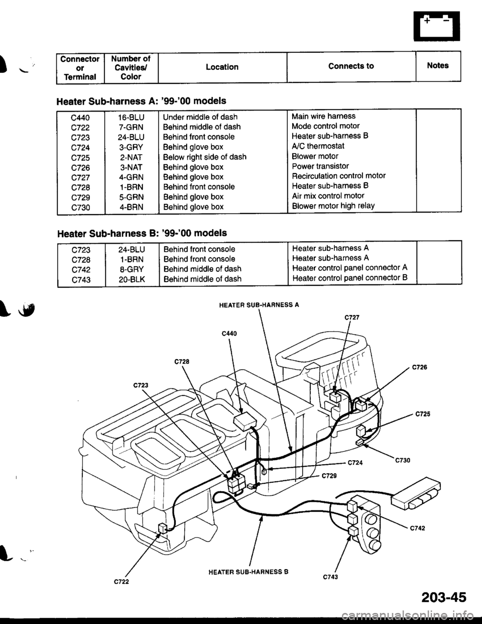
) ._'
Connectol
o1
Terminal
Number ot
Cavltles/
Color
LocationConnects toNotes
Heater Sub-harness A: '99-'00 models
c440
c722
c723
c724
wlzc
c726
c727
c728
c729
c730
16.8LU
7-GRN
24-BLU
3-GRY
2-NAT
3-NAT
4.GRN
1-BRN
5-GRN
4-BRN
Under middle of dash
Behind middle of dash
Behind front console
Behind glove box
Below right side of dash
Behind glove box
Behind glove box
Behind front console
Behind glove box
Behind glove box
Main wire harness
Mode control motor
Heater sub-harness B
A'lC thermostat
Blower motor
Power transistor
Recirculation control motor
Heater sub-harness B
Air mix control motor
Blower motor high relay
Heater Sub-harness B: '99-'00 models
c723
c728
c742
c743
24.BLU
1-BRN
8-GRY
2O.BLK
Behind front console
Behind front console
Behind middle of dash
Behind middle of dash
Heater sub-harness A
Heater sub-harness A
Heater control panel conn€ctor A
Heater control oanel connector B
HEATER SUB.HARNESS A
HEATER SUB-HARNESS B
203-45