Page 1394 of 2189
Troubleshooting -'99 - 00 Models
Self-diagnosis Function
The heater control panel has a self-diagnosis function.
Running the Self-diagnosis Funqtion
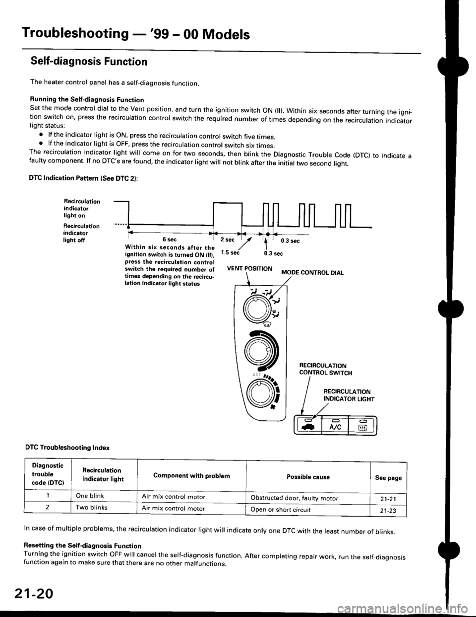
Set the mode control dial to the Vent position, and turn the ignition switch ON fll). Within six seconds after turnang the igni_tion switch on. press the recirculation control switch the required number of times depending on the recirculation indicatorlight status:
.lftheindicatorlightisON,presstherecirculationcontrolswitchfivetrmes.
.lftheindicatorlightisOFF,presstherecirculationcontrol switch six rrmes.The recirculation indicator light will come on for two seconds. then blink the Diagnostic Trouble code {DTc} to indicate afaulty component. lf no DTc's are found, the indicator light will not blink after the initial two second liqht.
DTC Indication Pattern (S6e DTC 2l:
Recirculationindicato.light on
Recirculationindicatorlight off2 sec
,/1.5 soct
' 0,3 secWithin six seconds atter theignition switch is turned ON (lll,pross the recirculation controlswitch the required number ottimes depending on the rocircu-lation indicetor light status
0.3 sec
VENT POSITIONMODE CONTROL DIAL
RECIRCULATIONCONTROL SWTCH
DTC Troubleshooting Index
Diagnostic
trouble
code (DTCI
Rgcirculation
indicator lightComponent with problemPossible causeSee page
One blinkAir mix control motorObstructed door, laulty motor21-21
2Two blinksAir mix control motorOpen or short circuit21-23
ln case of multiple problems, the recirculation indicator light will indicate only one DTc with the least number of blinks.
Resetting the Self-diagnosis FunctionTurning the ignition switch OFF will cancel the self-diagnosis function, After completing repair work, run the setf diagnosisfunction again to make sure that there are no other malfunctions.
21-20
@
At
V'
Page 1395 of 2189
Air Mix Gontrol Motor
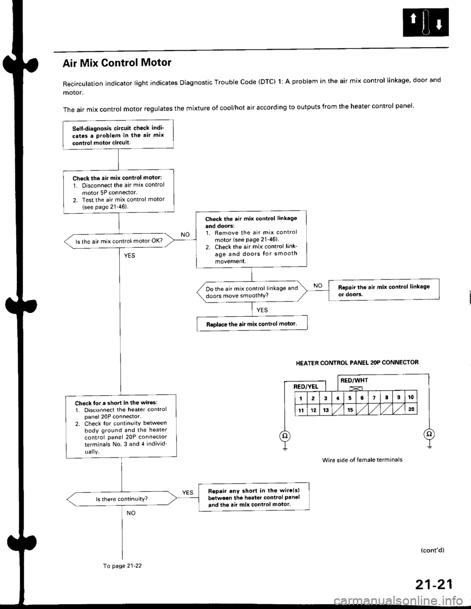
Recirculation indicator light indicates Diagnostic Trouble code (DTC) 1l A problem in the air mix control linkage, door and
motor.
The air mix control motor regulates the mixture of cool/hot air according to outputs from the heater control panel'
Self-diagnosis circuit check indi'
cates a Problem in the air mix
conlrol motor circuit,
Check th6 aii mix conirol motor:
1. Disconnect the air mix control
motor 5P connector.
2. Test the air mix control motor(see page 21-46).
check the air mix control linkage
and doors:1. Remove the air mix control
motor (see Page 21-46)
2. Check the air mix control link-
age and doors lor smooth
movement.
ls the air mix control motor OK?
Do the air mix control linkage and
doors move smoolhlY?
R€olace the air mix control motor'
Check tor a short in the wiles:
1. Disconnect the heater controlpanel 20P connector-2. Check for continuitY between
body ground and the heater
control panel 20P connector
terminals No.3 and 4 individ'
uaIY.
Ropair any short in th€ wire{s}
betweon the heater control Paneland the air mix control motor'
HEATER CONTROL PANEL 2OP CONNECTOR
RED/WHTRED/YEL
Wire side ot female terminals
(cont'd)
fo page 21-22
21-21
Page 1396 of 2189
Troubleshooting -'gg - 00 Models
Air Mix Control Motor (cont'dl
Frcm page21-21
AIR MIX CONTROL MOTOR5P CONNECTORWire side ot female terminals
Check fo..n open in the wires:Check for continuity between lol-lowing terminals of the heatercontrol panel 20P connector andthe air mix control motor 5P con-
20P: 5P:No3 _ No. 1No.4 - No.5
Repair any open in the wiro(s)bdtwoon tha hoator control panaland air mix control motor.
Check for loo3e wires or poorconneclions at the heater controlpanol 20P connoctor and at theair mix control motor 5P connoc-to.. It the connections .rc good,substitute a known-good hoaiercontrol panel, and rech6ck. lf thesymptom/indicrtion goes away,replac6 the original heater con-trol panel.
21-22
Page 1397 of 2189
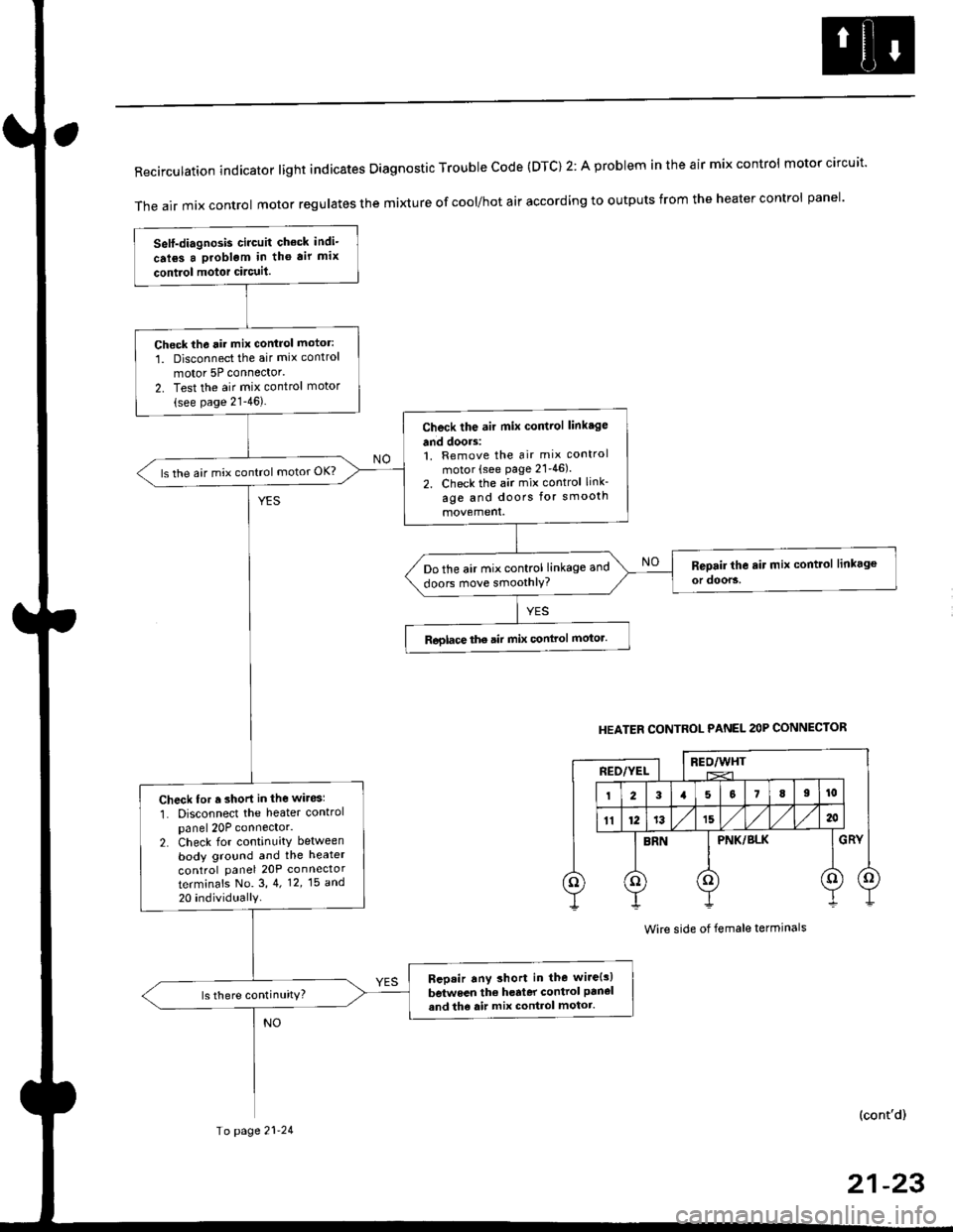
RecirculationindicatorIightindicatesDiagnosticTroublecode(DTc)2:AprobIemintheairmixcontro|motorcircuit.
The air mix control motor regutates the mi)dure of cool/hot air according to outputs from the heater control panel'
Self-diagnosis circuit check indi-
crl6s a problgm in tho air mix
contiol motor circuit.
Check th6 rir mix control motor:
1. Disconnect the air mix control
motor 5P connector'
2. Test the air mix control motor(see page 21-46).
Check the air mix control linkage
and doors:1. Remove the air mix control
motor (see page 21'46).
2. Check the air mix control link-
age and doors for smooth
ls the air mix control motor OK?
Do the air mix control linkage and
doors move smoothlY?
Roglace the air mix conlrol motor.
Check for r short in the wiresl
1. Disconnect the heater controlpanel 20P connector.2. Check for continuity between
body ground and the heater
control panel 20P connector
terminafs No. 3,4. 12,15 a^d
20 individually
Bep.ir any short in the wire{s)
between the h€rter control panel
and th6 air mix control motor.ls there continuity?
HEATER CONTROL PANEL 2OP CONNECTOR
BEO/WHTREO/YEL
PNK/BLK
Wire side of female terminals
(cont'd)
Io page 21-24
21-23
Page 1398 of 2189
Troubleshooting -'99 - 00 Models
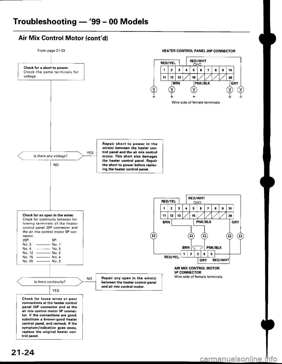
Check tor a short to power:
Check the same terminals forvoltage.
Rapair short to pow6r in thewirelsl botween the heater con-trol panel and the ai. mix controlmolor. This short also damag.sthe heater control panel. Ropairthe short to power betoro replac-ing the heater control panel.
ls there any voltage?
Check for an open in the wire3:Check for continuity between following terminals of the heatercontrol panel 20P connector andthe air max control motor 5P connector.20Pt 5P:No3 _ No. 1No 4 _ No. 5No_ 12 - No. 2No. 15 - No.4No 20 - No.3
Bepair any open in the wire(s)between the heator control paneland air mix control motor,
Check tor loose wires or poorconnections at the heator controloanel 20P connector and at th.air mix control motor 5P connec-tor, ll the connections rre good,substitute a known-good heatercontrol oanel. and recheck. lf thesymptom/indication goes awry,replace the original heater con-trol oanel,
Air Mix Control Motor (cont'dl
From page 21-23HEATER CONTROL PANEL 2OP CONNECTOR
AIR MIX CONTROL MOTOR5P CONNECTORWire side of lemale terminals
Wire side of female terminals
21-24
Page 1410 of 2189
Troubleshooting -'99 - 00 Models
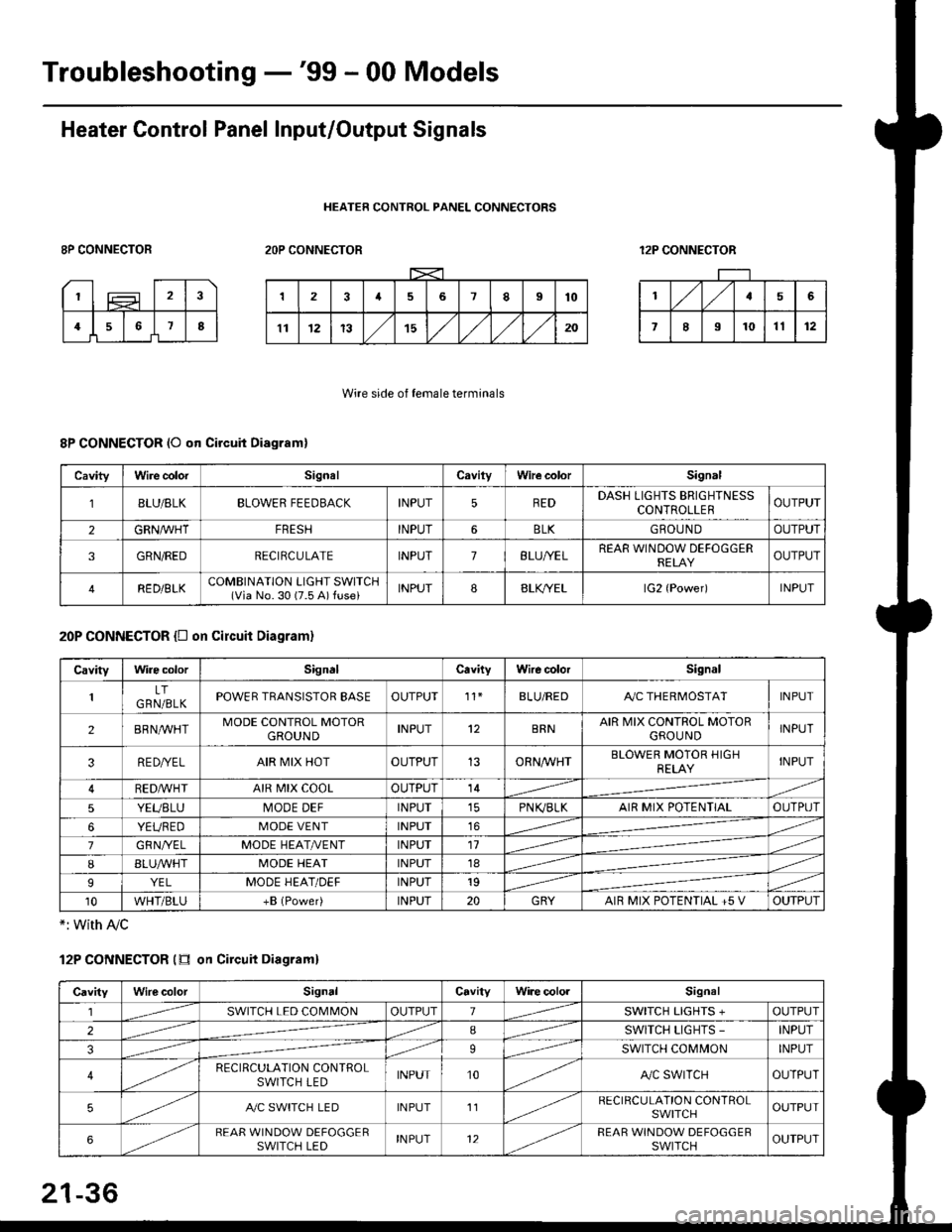
Heater Control Panel Input/Output Signals
HEATER CONTROL PANEL CONNECTORS
8P CONNECTOR2OP CONNECTOR12P CONNECTOR
Wire side of female terminals
8P CONNECTOR (O qn Circuit Diagram)
20P CONNECTOR {D on circuit Diagram}
*: with Ay'c
12P CONNECTOR (tr on Circuit Diagraml
CavityWire colorSignalCavilyWhe colorSignal
BLU/8LKBLOWER FEEDBACKINPUT5REDDASH LIGHTS BRIGHTNESSCONTROLLEROUTPUT
2GRN/lVHTFRESHINPUT6BLKGBOU N DOUTPUT
3GRN/REDRECIRCULATEINPUT7BLU/YELREAR WINDOW DEFOGGERRELAYOUTPUT
4RED/BLKCOMBINATION LIGHT SWITCH(Via No. 30 (7.5 A) fuse)INPUT88LfiELlG2 {Power)INPUT
CavityWire colorSignalCavityWire colorSignal
LTGRN/BLKPOWER TRANSISTOR EASEOUTPUT't1BLU/REDAy'C THERMOSTATINPUT
2BRNMHTMODE CONTROL MOTORGROUNDINPUT12BRNAIR MIX CONTROL MOTORGROU NDINPUT
3RE D/YELAIR MIX HOTOUTPUT13ORNAA/HTBLOWER MOTOR HIGHRELAYINPUT
RED,ryvHIAIR MIX COOLOUTPUT14
5YEUBLUMODE DEFINPUTPN K,/BLKAIR MIX POTENTIALOUTPUT
6YEUREDMODE VENTINPUT16
7GRNI/ELMODE HEAT/r'ENTINPUT11
IBLUAVHTMODE HEATINPUT18
9YELMODE HEAT/DEFINPUT19
10WHT/BLU+B (Power)INPUT20GRYAIR MIX POTENTIAL +5 VOUTPUT
CavityWilecolorSignalCavityWi.e cololSignal
lSWITCH LED COMMONOUTPUT1SWITCH LIGHTS +OUTPUT
2ISWITCH LIGHTS -INPUT
39SWITCH COMMONINPUT
4RECIRCULATION CONTROLSWITCH LEDINPUT10A,/C SWITCHOUTPUT
5A./C SWITCH LEDINPUT11RECIRCULATION CONTROLSWITCHOUTPUT
6REAR WINDOW DEFOGGERSWITCH LEDINPUT12REAR WINDOW DEFOGGEBSWITCHOUTPUT
21-36
Page 1414 of 2189
Heater Unit
Replacement (cont'dl
6.
7.
8.
9.
Remove the dashboard (see section 20).
Remove the heater duct (see page 21-37) or evapo-
rator (see page 22-28).
Disconnect the connectors from the mode control
motor and air mix control motor ('99 - 00 models),
then remove the wire harness clips and wire har-
ness from the heater unit. Remove the clip from the
heater duct, then remove the two mounting nuts
and the heater unit.
6x1.0mm9.8 N.m 11.0 kgl.m,7.2 lbf.ftl
HEATER UNIT
lnstall in the reverse order of removal. Make note of
the following items.
Apply sealant to the grommets.
Do not interchange the inlet and outlet heater
hoses. Make sure that the clamps are secure.
Refill the cooling system with engine coolant
(see section 10).
Connect all cables, and make sure they are prop-
erly adjusted (see page 21-44 (96 - 98 models)
or page 21-45 ('99 - 00 models)).
Make sure that there is no air leakage.
21-40
Page 1416 of 2189
Heater Control Panel
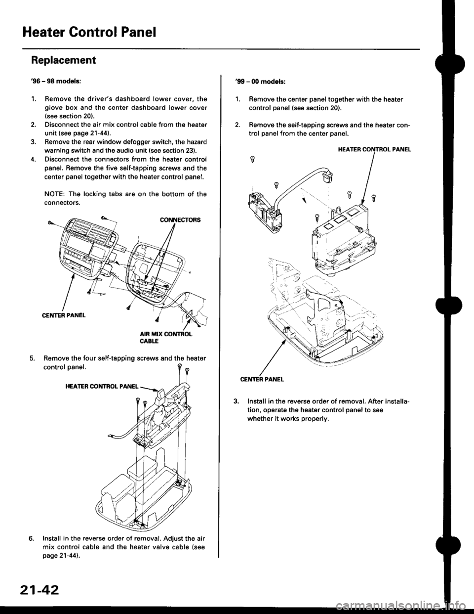
'95 - 98 modolsi
Remove the driver's dashboard lower cover, the
glove box and the center dashboard lower cover(see section 20).
Disconnect the air mix control cabls from the heater
unit {see page 21-44).
Remove the rear window defogger switch, the hazard
warning switch and the audio unit (see section 23).
Disconnect the connectors from the heater control
panel. Remove the five self-tapping screws and the
center panel together with the heater control panel.
NOTE: The locking tabs are on the bottom of the
connecrors.
Install in the .everse order of removal. Adjust the air
mix control cable and the heater valve cable {seepage 21-44)..
Replacement
1.
Remove the four self-tapping screws and the heater
21-42
1.
'9!, - 00 modols:
Remove the center panel together with the heater
control panel (see section 20).
Remove the self-tapping screws and the heater con-
trol panelfrom the center Danel.
Install in the reverse order of removal. After
tion, operate the heater control panel to see
whether it works properly.
installa-