1998 DODGE RAM 1500 Reverse
[x] Cancel search: ReversePage 1764 of 2627

(22) Remove bearing puller tools and rear main-
shaft bearing from output shaft.
(23) Remove reverse gear thrust washer (Fig. 59).
(24) Remove reverse gear and synchro components
as assembly (Fig. 60).CAUTION: Do not disassemble synchro compo-
nents unless they are damaged. If synchro sleeve
or struts require service, mark position of sleeve on
hub before removal. Correct sleeve position is
important as sleeve can be installed backwards
causing shift problems.
(25) Remove reverse gear bearing assembly from
mainshaft (Fig. 60).
(26) Remove reverse gear bearing spacer from
mainshaft (Fig. 61).
(27) Remove reverse clutch gear snap ring (Fig.
61). Heavy duty snap ring pliers will be required to
spread the ring far enough to remove it.
Fig. 58 MAINSHAFT REAR BEARING
1-JAWS
2 - COLLAR
3 - FLANGE
4 - MAINSHAFT
5 - PULLER
6 - TIGHTENING WRENCH
7 - HOLDING WRENCH
8 - RODS
Fig. 59 REVERSE GEAR THRUST WASHER
1 - REVERSE GEAR
2 - THRUST WASHER
Fig. 60 REVERSE GEAR, BEARING, AND STOP
RING
1 - FIRST GEAR
2 - REVERSE GEAR ASSEMBLY
3 - BEARING ASSEMBLY
4 - STOP RING
Fig. 61 REVERSE GEAR BEARING SPACER AND
FIRST GEAR SNAP RING
1 - CLUTCH GEAR SNAP RING
2 - REVERSE GEAR BEARING SPACER
DRMANUAL TRANSMISSION - NV4500 21 - 61
MANUAL TRANSMISSION - NV4500 (Continued)
Page 1765 of 2627
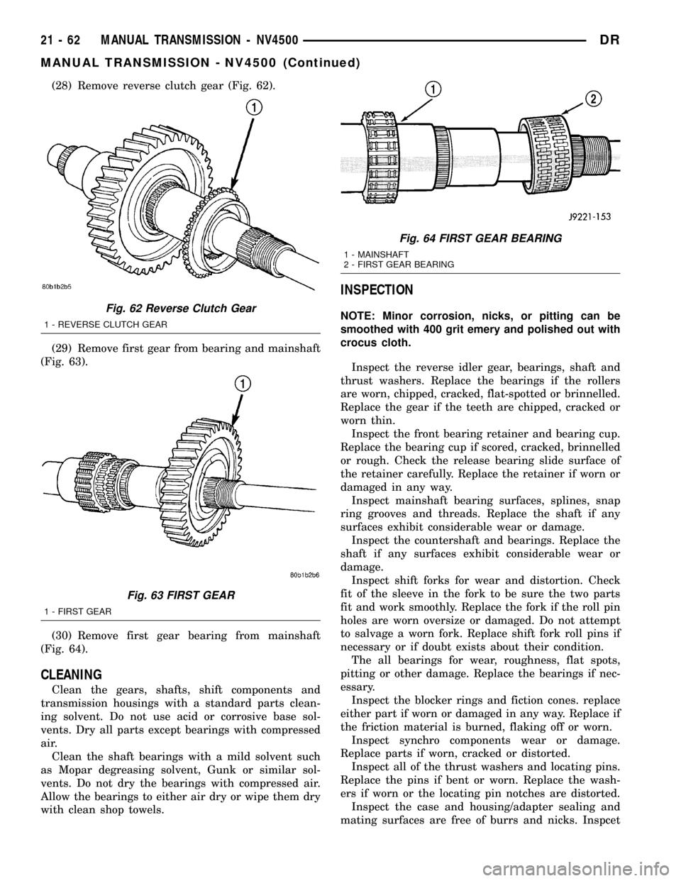
(28) Remove reverse clutch gear (Fig. 62).
(29) Remove first gear from bearing and mainshaft
(Fig. 63).
(30) Remove first gear bearing from mainshaft
(Fig. 64).
CLEANING
Clean the gears, shafts, shift components and
transmission housings with a standard parts clean-
ing solvent. Do not use acid or corrosive base sol-
vents. Dry all parts except bearings with compressed
air.
Clean the shaft bearings with a mild solvent such
as Mopar degreasing solvent, Gunk or similar sol-
vents. Do not dry the bearings with compressed air.
Allow the bearings to either air dry or wipe them dry
with clean shop towels.
INSPECTION
NOTE: Minor corrosion, nicks, or pitting can be
smoothed with 400 grit emery and polished out with
crocus cloth.
Inspect the reverse idler gear, bearings, shaft and
thrust washers. Replace the bearings if the rollers
are worn, chipped, cracked, flat-spotted or brinnelled.
Replace the gear if the teeth are chipped, cracked or
worn thin.
Inspect the front bearing retainer and bearing cup.
Replace the bearing cup if scored, cracked, brinnelled
or rough. Check the release bearing slide surface of
the retainer carefully. Replace the retainer if worn or
damaged in any way.
Inspect mainshaft bearing surfaces, splines, snap
ring grooves and threads. Replace the shaft if any
surfaces exhibit considerable wear or damage.
Inspect the countershaft and bearings. Replace the
shaft if any surfaces exhibit considerable wear or
damage.
Inspect shift forks for wear and distortion. Check
fit of the sleeve in the fork to be sure the two parts
fit and work smoothly. Replace the fork if the roll pin
holes are worn oversize or damaged. Do not attempt
to salvage a worn fork. Replace shift fork roll pins if
necessary or if doubt exists about their condition.
The all bearings for wear, roughness, flat spots,
pitting or other damage. Replace the bearings if nec-
essary.
Inspect the blocker rings and fiction cones. replace
either part if worn or damaged in any way. Replace if
the friction material is burned, flaking off or worn.
Inspect synchro components wear or damage.
Replace parts if worn, cracked or distorted.
Inspect all of the thrust washers and locating pins.
Replace the pins if bent or worn. Replace the wash-
ers if worn or the locating pin notches are distorted.
Inspect the case and housing/adapter sealing and
mating surfaces are free of burrs and nicks. InspcetFig. 62 Reverse Clutch Gear
1 - REVERSE CLUTCH GEAR
Fig. 63 FIRST GEAR
1 - FIRST GEAR
Fig. 64 FIRST GEAR BEARING
1 - MAINSHAFT
2 - FIRST GEAR BEARING
21 - 62 MANUAL TRANSMISSION - NV4500DR
MANUAL TRANSMISSION - NV4500 (Continued)
Page 1766 of 2627
the alignment dowels in the case top surface and in
the housing/adapter are tight and in good condition.
Replace the gear case or housing/adapter if cracked
or broken.
ASSEMBLY
NOTE: Gaskets are not used in the transmission.
Use Mopar Silicone Sealer or equivalent on all gear
case and extension housing sealing surfaces.
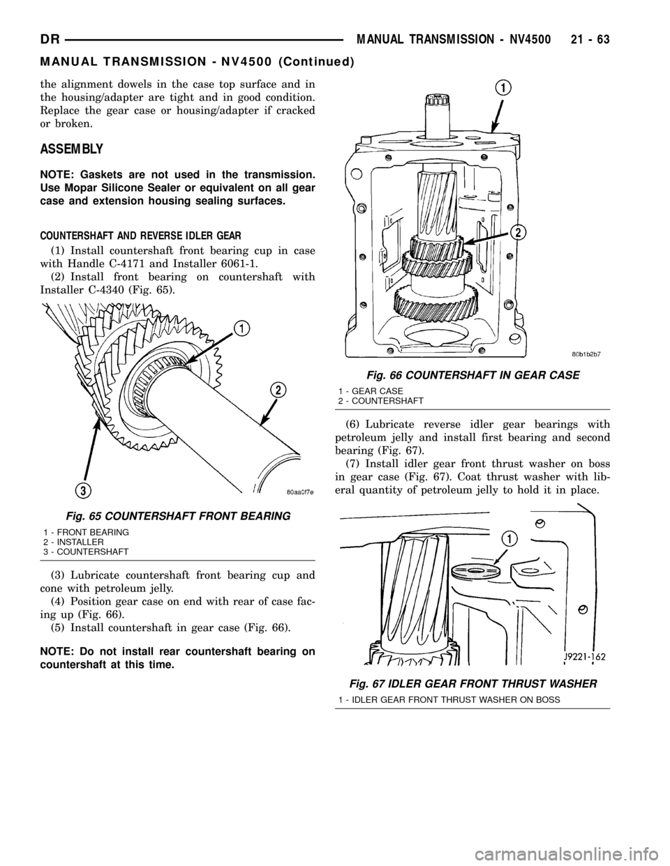
COUNTERSHAFT AND REVERSE IDLER GEAR
(1) Install countershaft front bearing cup in case
with Handle C-4171 and Installer 6061-1.
(2) Install front bearing on countershaft with
Installer C-4340 (Fig. 65).
(3) Lubricate countershaft front bearing cup and
cone with petroleum jelly.
(4) Position gear case on end with rear of case fac-
ing up (Fig. 66).
(5) Install countershaft in gear case (Fig. 66).
NOTE: Do not install rear countershaft bearing on
countershaft at this time.(6) Lubricate reverse idler gear bearings with
petroleum jelly and install first bearing and second
bearing (Fig. 67).
(7) Install idler gear front thrust washer on boss
in gear case (Fig. 67). Coat thrust washer with lib-
eral quantity of petroleum jelly to hold it in place.
Fig. 65 COUNTERSHAFT FRONT BEARING
1 - FRONT BEARING
2 - INSTALLER
3 - COUNTERSHAFT
Fig. 66 COUNTERSHAFT IN GEAR CASE
1 - GEAR CASE
2 - COUNTERSHAFT
Fig. 67 IDLER GEAR FRONT THRUST WASHER
1 - IDLER GEAR FRONT THRUST WASHER ON BOSS
DRMANUAL TRANSMISSION - NV4500 21 - 63
MANUAL TRANSMISSION - NV4500 (Continued)
Page 1767 of 2627
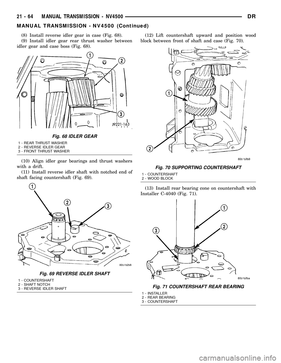
(8) Install reverse idler gear in case (Fig. 68).
(9) Install idler gear rear thrust washer between
idler gear and case boss (Fig. 68).
(10) Align idler gear bearings and thrust washers
with a drift.
(11) Install reverse idler shaft with notched end of
shaft facing countershaft (Fig. 69).(12) Lift countershaft upward and position wood
block between front of shaft and case (Fig. 70).
(13) Install rear bearing cone on countershaft with
Installer C-4040 (Fig. 71).
Fig. 68 IDLER GEAR
1 - REAR THRUST WASHER
2 - REVERSE IDLER GEAR
3 - FRONT THRUST WASHER
Fig. 69 REVERSE IDLER SHAFT
1 - COUNTERSHAFT
2 - SHAFT NOTCH
3 - REVERSE IDLER SHAFT
Fig. 70 SUPPORTING COUNTERSHAFT
1 - COUNTERSHAFT
2 - WOOD BLOCK
Fig. 71 COUNTERSHAFT REAR BEARING
1 - INSTALLER
2 - REAR BEARING
3 - COUNTERSHAFT
21 - 64 MANUAL TRANSMISSION - NV4500DR
MANUAL TRANSMISSION - NV4500 (Continued)
Page 1768 of 2627
(14) Remove wood block from under countershaft
and lower countershaft front bearing into front bear-
ing cup.
(15) Lubricate countershaft rear bearing cup and
cone with petroleum jelly.
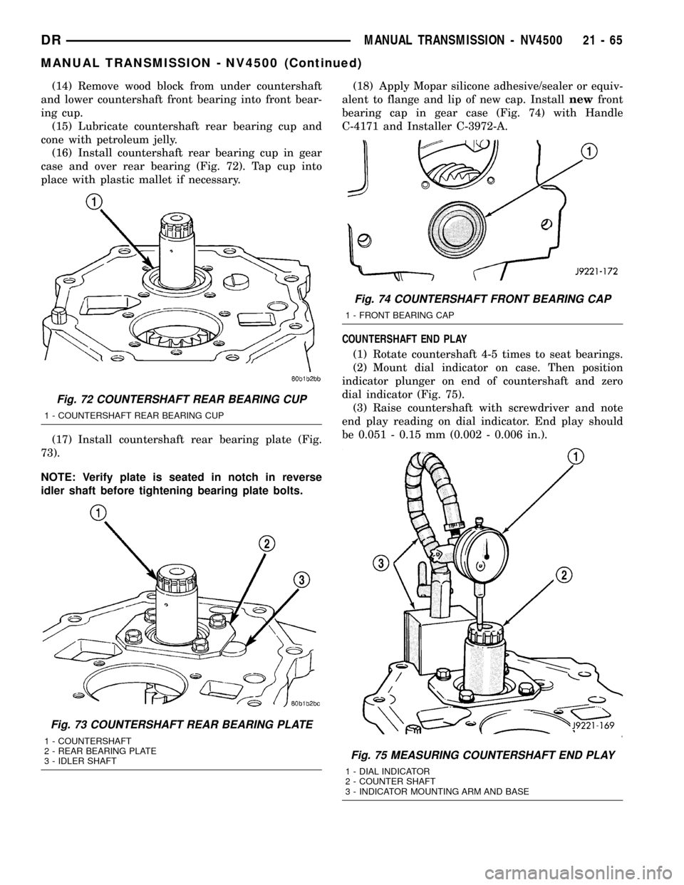
(16) Install countershaft rear bearing cup in gear
case and over rear bearing (Fig. 72). Tap cup into
place with plastic mallet if necessary.
(17) Install countershaft rear bearing plate (Fig.
73).
NOTE: Verify plate is seated in notch in reverse
idler shaft before tightening bearing plate bolts.(18) Apply Mopar silicone adhesive/sealer or equiv-
alent to flange and lip of new cap. Installnewfront
bearing cap in gear case (Fig. 74) with Handle
C-4171 and Installer C-3972-A.
COUNTERSHAFT END PLAY
(1) Rotate countershaft 4-5 times to seat bearings.
(2) Mount dial indicator on case. Then position
indicator plunger on end of countershaft and zero
dial indicator (Fig. 75).
(3) Raise countershaft with screwdriver and note
end play reading on dial indicator. End play should
be 0.051 - 0.15 mm (0.002 - 0.006 in.).
Fig. 72 COUNTERSHAFT REAR BEARING CUP
1 - COUNTERSHAFT REAR BEARING CUP
Fig. 73 COUNTERSHAFT REAR BEARING PLATE
1 - COUNTERSHAFT
2 - REAR BEARING PLATE
3 - IDLER SHAFT
Fig. 74 COUNTERSHAFT FRONT BEARING CAP
1 - FRONT BEARING CAP
Fig. 75 MEASURING COUNTERSHAFT END PLAY
1 - DIAL INDICATOR
2 - COUNTER SHAFT
3 - INDICATOR MOUNTING ARM AND BASE
DRMANUAL TRANSMISSION - NV4500 21 - 65
MANUAL TRANSMISSION - NV4500 (Continued)
Page 1769 of 2627
(4) Remove countershaft rear bearing plate.
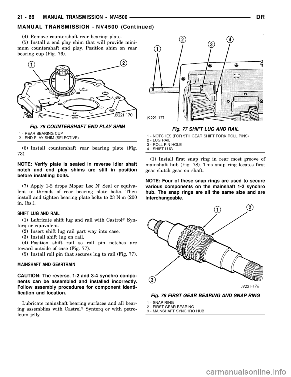
(5) Install a end play shim that will provide mini-
mum countershaft end play. Position shim on rear
bearing cup (Fig. 76).
(6) Install countershaft rear bearing plate (Fig.
73).
NOTE: Verify plate is seated in reverse idler shaft
notch and end play shims are still in position
before installing bolts.
(7) Apply 1-2 drops Mopar Loc N' Seal or equiva-
lent to threads of rear bearing plate bolts. Then
install and tighten bearing plate bolts to 23 N´m (200
in. lbs.).
SHIFT LUG AND RAIL
(1) Lubricate shift lug and rail with CastroltSyn-
torq or equivalent.
(2) Insert shift lug rail part way into case.
(3) Install shift lug on rail.
(4) Position shift rail so roll pin notches are
toward outside of case (Fig. 77).
(5) Install roll pin that secures lug to rail (Fig. 77).
MAINSHAFT AND GEARTRAIN
CAUTION: The reverse, 1-2 and 3-4 synchro compo-
nents can be assembled and installed incorrectly.
Follow assembly procedures for component identi-
fication and location.
Lubricate mainshaft bearing surfaces and all bear-
ing assemblies with CastroltSyntorq or with petro-
leum jelly.(1) Install first snap ring in rear most groove of
mainshaft hub (Fig. 78). This snap ring locates first
gear clutch gear on shaft.
NOTE: Four of these snap rings are used to secure
various components on the mainshaft 1-2 synchro
hub. The snap rings are all the same size and are
interchangeable.
Fig. 76 COUNTERSHAFT END PLAY SHIM
1 - REAR BEARING CUP
2 - END PLAY SHIM (SELECTIVE)Fig. 77 SHIFT LUG AND RAIL
1 - NOTCHES (FOR 5TH GEAR SHIFT FORK ROLL PINS)
2 - LUG RAIL
3 - ROLL PIN HOLE
4 - SHIFT LUG
Fig. 78 FIRST GEAR BEARING AND SNAP RING
1 - SNAP RING
2 - FIRST GEAR BEARING
3 - MAINSHAFT SYNCHRO HUB
21 - 66 MANUAL TRANSMISSION - NV4500DR
MANUAL TRANSMISSION - NV4500 (Continued)
Page 1775 of 2627
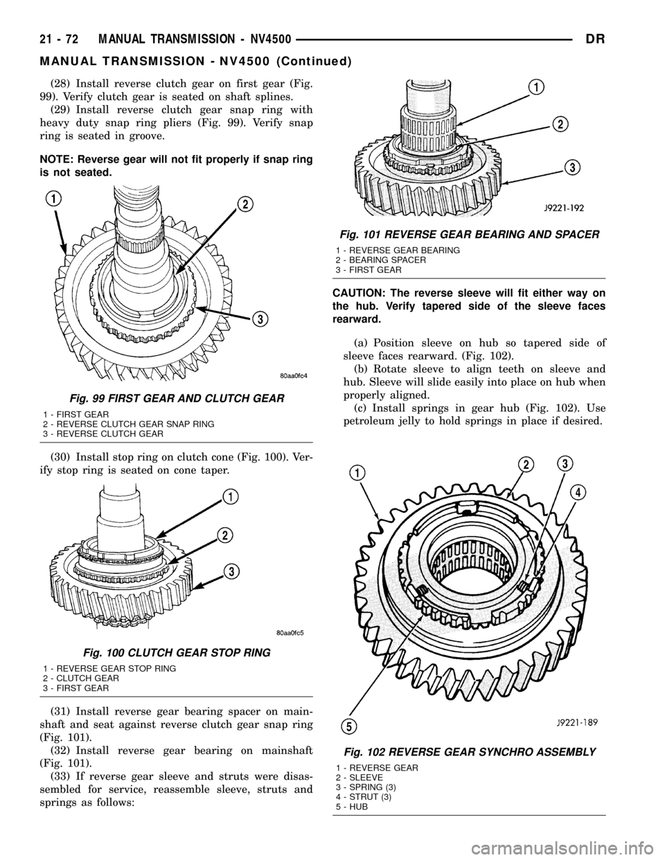
(28) Install reverse clutch gear on first gear (Fig.
99). Verify clutch gear is seated on shaft splines.
(29) Install reverse clutch gear snap ring with
heavy duty snap ring pliers (Fig. 99). Verify snap
ring is seated in groove.
NOTE: Reverse gear will not fit properly if snap ring
is not seated.
(30) Install stop ring on clutch cone (Fig. 100). Ver-
ify stop ring is seated on cone taper.
(31) Install reverse gear bearing spacer on main-
shaft and seat against reverse clutch gear snap ring
(Fig. 101).
(32) Install reverse gear bearing on mainshaft
(Fig. 101).
(33) If reverse gear sleeve and struts were disas-
sembled for service, reassemble sleeve, struts and
springs as follows:CAUTION: The reverse sleeve will fit either way on
the hub. Verify tapered side of the sleeve faces
rearward.
(a) Position sleeve on hub so tapered side of
sleeve faces rearward. (Fig. 102).
(b) Rotate sleeve to align teeth on sleeve and
hub. Sleeve will slide easily into place on hub when
properly aligned.
(c) Install springs in gear hub (Fig. 102). Use
petroleum jelly to hold springs in place if desired.
Fig. 102 REVERSE GEAR SYNCHRO ASSEMBLY
1 - REVERSE GEAR
2 - SLEEVE
3 - SPRING (3)
4 - STRUT (3)
5 - HUB
Fig. 99 FIRST GEAR AND CLUTCH GEAR
1 - FIRST GEAR
2 - REVERSE CLUTCH GEAR SNAP RING
3 - REVERSE CLUTCH GEAR
Fig. 100 CLUTCH GEAR STOP RING
1 - REVERSE GEAR STOP RING
2 - CLUTCH GEAR
3 - FIRST GEAR
Fig. 101 REVERSE GEAR BEARING AND SPACER
1 - REVERSE GEAR BEARING
2 - BEARING SPACER
3 - FIRST GEAR
21 - 72 MANUAL TRANSMISSION - NV4500DR
MANUAL TRANSMISSION - NV4500 (Continued)
Page 1776 of 2627
(d) Compress first spring with flat blade screw-
driver and slide strut into position in hub slot.
Then work spring into seat in strut with small
hooked tool or screwdriver.
(e) Install second and third struts in same man-
ner as described in step (d).
(f) Work sleeve upward on hub until struts are
centered and seated in sleeve. Sleeve should be in
neutral position after seating struts.
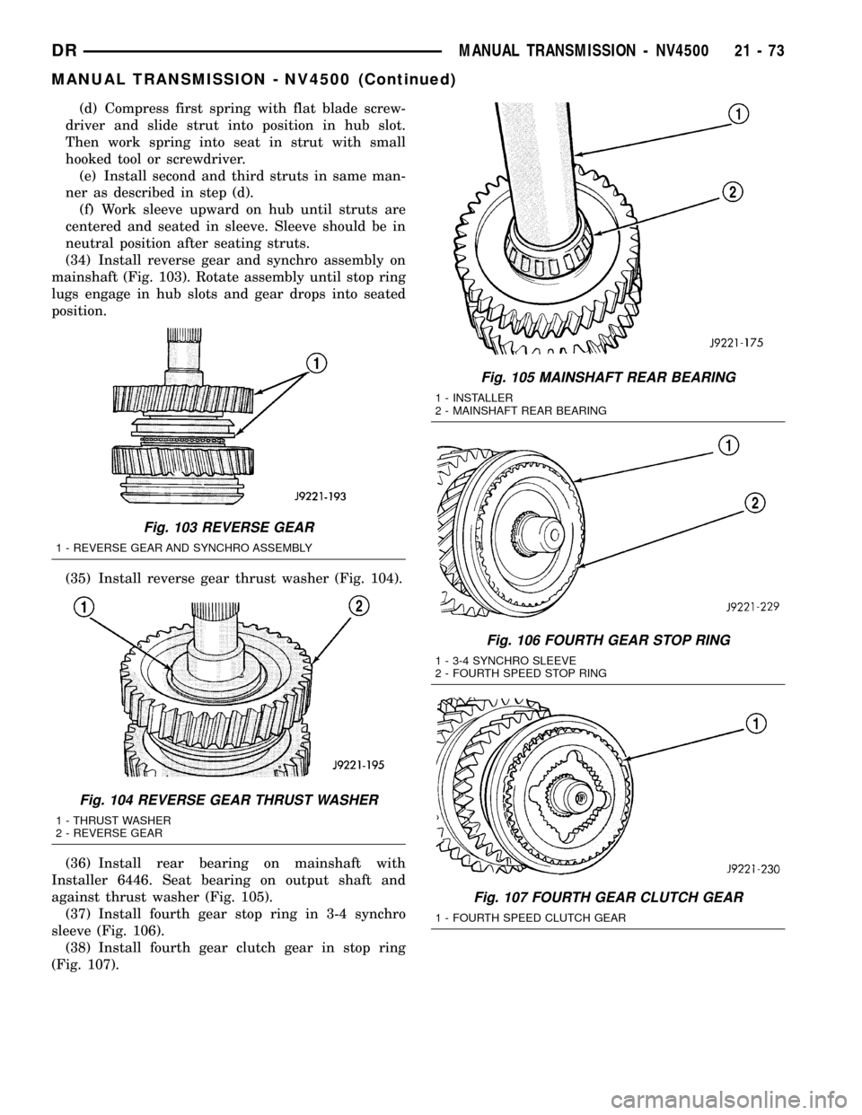
(34) Install reverse gear and synchro assembly on
mainshaft (Fig. 103). Rotate assembly until stop ring
lugs engage in hub slots and gear drops into seated
position.
(35) Install reverse gear thrust washer (Fig. 104).
(36) Install rear bearing on mainshaft with
Installer 6446. Seat bearing on output shaft and
against thrust washer (Fig. 105).
(37) Install fourth gear stop ring in 3-4 synchro
sleeve (Fig. 106).
(38) Install fourth gear clutch gear in stop ring
(Fig. 107).
Fig. 103 REVERSE GEAR
1 - REVERSE GEAR AND SYNCHRO ASSEMBLY
Fig. 104 REVERSE GEAR THRUST WASHER
1 - THRUST WASHER
2 - REVERSE GEAR
Fig. 105 MAINSHAFT REAR BEARING
1 - INSTALLER
2 - MAINSHAFT REAR BEARING
Fig. 106 FOURTH GEAR STOP RING
1 - 3-4 SYNCHRO SLEEVE
2 - FOURTH SPEED STOP RING
Fig. 107 FOURTH GEAR CLUTCH GEAR
1 - FOURTH SPEED CLUTCH GEAR
DRMANUAL TRANSMISSION - NV4500 21 - 73
MANUAL TRANSMISSION - NV4500 (Continued)