1998 DODGE RAM 1500 Exhaust
[x] Cancel search: ExhaustPage 1261 of 2627

VALVE GUIDE SEALS
DESCRIPTION
The valve guide seals are made of rubber and
incorporate an integral steel valve spring seat. The
integral garter spring maintains consistent lubrica-
tion control to the valve stems.
VALVE SPRINGS
DESCRIPTION
The valve springs are made from high strength
chrome silicon steel. There are different springs for
intake and exhaust applications. The exhaust spring
has an external damper. The valve spring seat is
integral with the valve stem seal, which is a positive
type seal to control lubrication.
REMOVAL
(1) Remove the cylinder head cover(Refer to 9 -
ENGINE/CYLINDER HEAD/CYLINDER HEAD
COVER(S) - REMOVAL).
(2) Using Special Tool 8516 Valve Spring Compres-
sor, remove the rocker arms and the hydraulic lash
adjusters.
(3) Remove the spark plug for the cylinder the
valve spring and seal are to be removed from.
(4) Apply shop air to the cylinder to hold the
valves in place when the spring is removed.
NOTE: All six valve springs and seals are removed
in the same manner; this procedure only covers
one valve seal and valve spring.
(5) Using Special Tool 8387 Valve Spring Compres-
sor, compress the valve spring.
NOTE: It may be necessary to tap the top of the
valve spring to loosen the spring retainers locks
enough to be removed.
(6) Remove the two spring retainer lock halves.
NOTE: the valve spring is under tension use care
when releasing the valve spring compressor.
(7) Remove the valve spring compressor.
NOTE: The valve springs are NOT common between
intake and exhaust.
(8) Remove the spring retainer, and the spring.
(9) Remove the valve stem seal.
NOTE: The valve stem seals are common between
intake and exhaust.
INSTALLATION
NOTE: All six valve springs and seals are removed
in the same manner; this procedure only covers
one valve seal and valve spring.
(1) Apply shop air to the cylinder to hold the
valves in place while the spring is installed.
NOTE: The valve stem seals are common between
intake and exhaust.
(2) Install the valve stem seal.
NOTE: The valve springs are NOT common between
intake and exhaust.
(3) Install the spring retainer, and the spring.
(4) Using Special Tool 8387 Valve Spring Compres-
sor, compress the valve spring.
(5) Install the two spring retainer lock halves.
NOTE: the valve spring is under tension use care
when releasing the valve spring compressor.
(6) Remove the valve spring compressor.
(7) Disconnect the shop air to the cylinder.
(8) Install the spark plug for the cylinder the valve
spring and seal was installed on.
(9) Using Special Tool 8516 Valve Spring Compres-
sor, install the rocker arms and the hydraulic lash
adjusters.
(10) Install the cylinder head cover(Refer to 9 -
ENGINE/CYLINDER HEAD/CYLINDER HEAD
COVER(S) - INSTALLATION).
ENGINE BLOCK
DESCRIPTION
The cylinder block is made of cast iron. The block
is a closed deck design with the left bank forward. To
provide high rigidity and improved NVH an
enhanced compacted graphite bedplate is bolted to
the block. The block design allows coolant flow
between the cylinders bores, and an internal coolant
bypass to a single poppet inlet thermostat is included
in the cast aluminum front cover.
STANDARD PROCEDURE - CYLINDER BORE
HONING
Before honing, stuff plenty of clean shop towels
under the bores and over the crankshaft to keep
abrasive materials from entering the crankshaft
area.
(1) Used carefully, the Cylinder Bore Sizing Hone
C-823, equipped with 220 grit stones, is the best tool
9 - 38 ENGINE - 3.7LDR
Page 1280 of 2627
(5) Install fan blade assembly (Refer to 7 - COOL-
ING/ENGINE/FAN DRIVE VISCOUS CLUTCH -
INSTALLATION).
(6) Install radiator upper shroud and tighten fas-
teners to 11 N´m (95 in. lbs.).
(7) Connect electrical connector for shroud fan.
(8) Install radiator upper hose.
(9) Install accessory drive belt (Refer to 7 - COOL-
ING/ACCESSORY DRIVE/DRIVE BELTS - INSTAL-
LATION).
(10) Refill cooling system (Refer to 7 - COOLING -
STANDARD PROCEDURE).
(11) Connect negative cable to battery.
STRUCTURAL COVER
DESCRIPTION
The structural dust cover is made of die cast alu-
minum and joins the lower half of the transmission
bell housing to the engine bedplate.
OPERATION
The structural cover provides additional power-
train stiffness and reduces noise and vibration.
REMOVAL
(1) Raise vehicle on hoist.
(2) Remove the left hand exhaust pipe from
exhaust manifold.
(3) Loosen the right hand exhaust manifold-to-ex-
haust pipe retaining bolts.
(4) Remove the eight bolts retaining structural
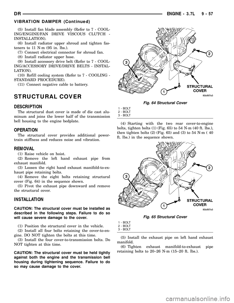
cover (Fig. 64) in the sequence shown.
(5) Pivot the exhaust pipe downward and remove
the structural cover.
INSTALLATION
CAUTION: The structural cover must be installed as
described in the following steps. Failure to do so
will cause severe damage to the cover.
(1) Position the structural cover in the vehicle.
(2) Install all four bolts retaining the cover-to-en-
gine. DO NOT tighten the bolts at this time.
(3) Install the four cover-to-transmission bolts. Do
NOT tighten at this time.
CAUTION: The structural cover must be held tightly
against both the engine and the transmission bell
housing during tightening sequence. Failure to do
so may cause damage to the cover.(4) Starting with the two rear cover-to-engine
bolts, tighten bolts (1) (Fig. 65) to 54 N´m (40 ft. lbs.),
then tighten bolts (2) (Fig. 65) and (3) to 54 N´m ( 40
ft. lbs.) in the sequence shown.
(5) Install the exhaust pipe on left hand exhaust
manifold.
(6) Tighten exhaust manifold-to-exhaust pipe
retaining bolts to 20±26 N´m (15±20 ft. lbs.).
Fig. 64 Structural Cover
1 - BOLT
2 - BOLT
3 - BOLT
Fig. 65 Structural Cover
1 - BOLT
2 - BOLT
3 - BOLT
DRENGINE - 3.7L 9 - 57
VIBRATION DAMPER (Continued)
Page 1284 of 2627
REAR MOUNT
REMOVAL
(1) Raise the vehicle on a hoist.
(2) Using a suitable jack, support transmission.
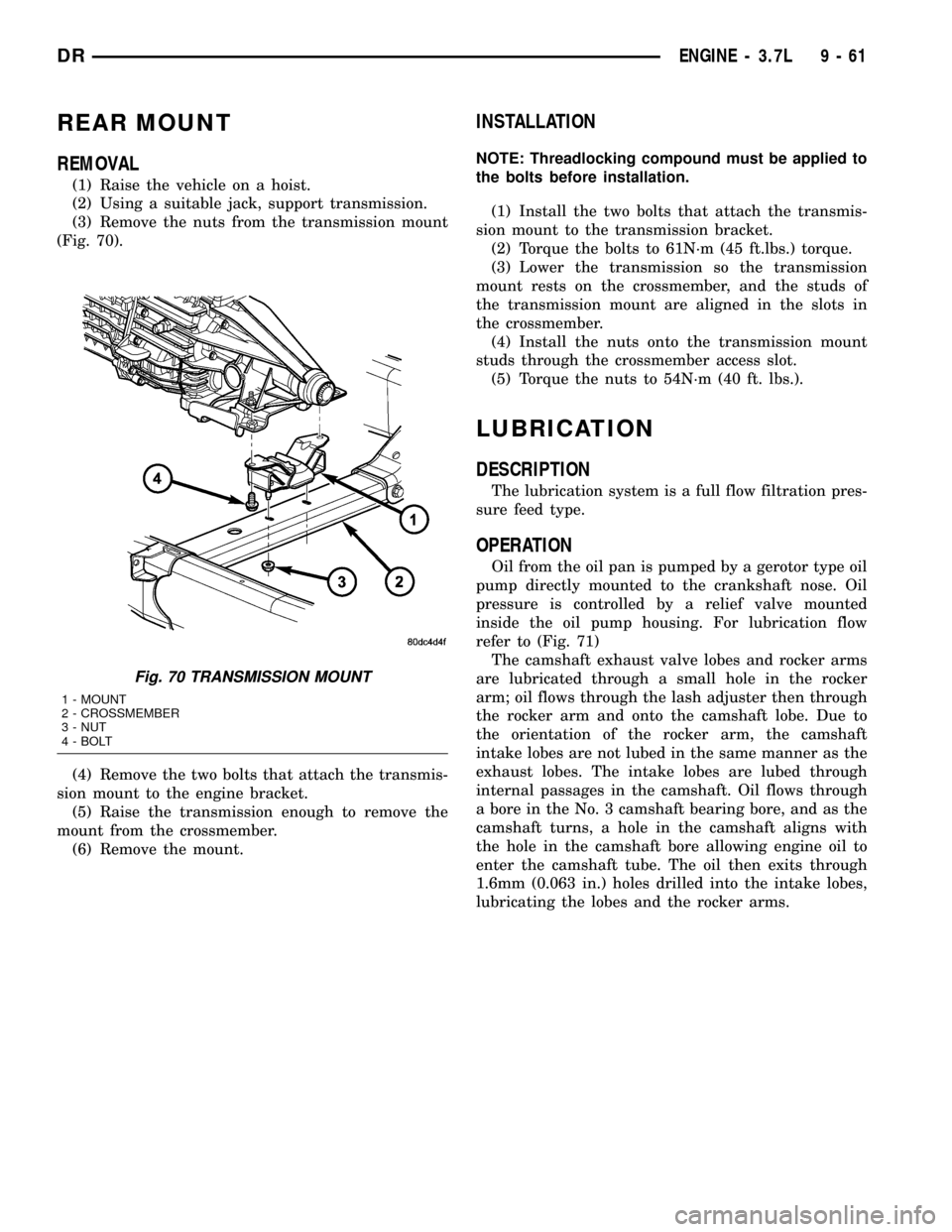
(3) Remove the nuts from the transmission mount
(Fig. 70).
(4) Remove the two bolts that attach the transmis-
sion mount to the engine bracket.
(5) Raise the transmission enough to remove the
mount from the crossmember.
(6) Remove the mount.
INSTALLATION
NOTE: Threadlocking compound must be applied to
the bolts before installation.
(1) Install the two bolts that attach the transmis-
sion mount to the transmission bracket.
(2) Torque the bolts to 61N´m (45 ft.lbs.) torque.
(3) Lower the transmission so the transmission
mount rests on the crossmember, and the studs of
the transmission mount are aligned in the slots in
the crossmember.
(4) Install the nuts onto the transmission mount
studs through the crossmember access slot.
(5) Torque the nuts to 54N´m (40 ft. lbs.).
LUBRICATION
DESCRIPTION
The lubrication system is a full flow filtration pres-
sure feed type.
OPERATION
Oil from the oil pan is pumped by a gerotor type oil
pump directly mounted to the crankshaft nose. Oil
pressure is controlled by a relief valve mounted
inside the oil pump housing. For lubrication flow
refer to (Fig. 71)
The camshaft exhaust valve lobes and rocker arms
are lubricated through a small hole in the rocker
arm; oil flows through the lash adjuster then through
the rocker arm and onto the camshaft lobe. Due to
the orientation of the rocker arm, the camshaft
intake lobes are not lubed in the same manner as the
exhaust lobes. The intake lobes are lubed through
internal passages in the camshaft. Oil flows through
a bore in the No. 3 camshaft bearing bore, and as the
camshaft turns, a hole in the camshaft aligns with
the hole in the camshaft bore allowing engine oil to
enter the camshaft tube. The oil then exits through
1.6mm (0.063 in.) holes drilled into the intake lobes,
lubricating the lobes and the rocker arms.
Fig. 70 TRANSMISSION MOUNT
1 - MOUNT
2 - CROSSMEMBER
3 - NUT
4 - BOLT
DRENGINE - 3.7L 9 - 61
Page 1297 of 2627
EXHAUST MANIFOLD
DESCRIPTION
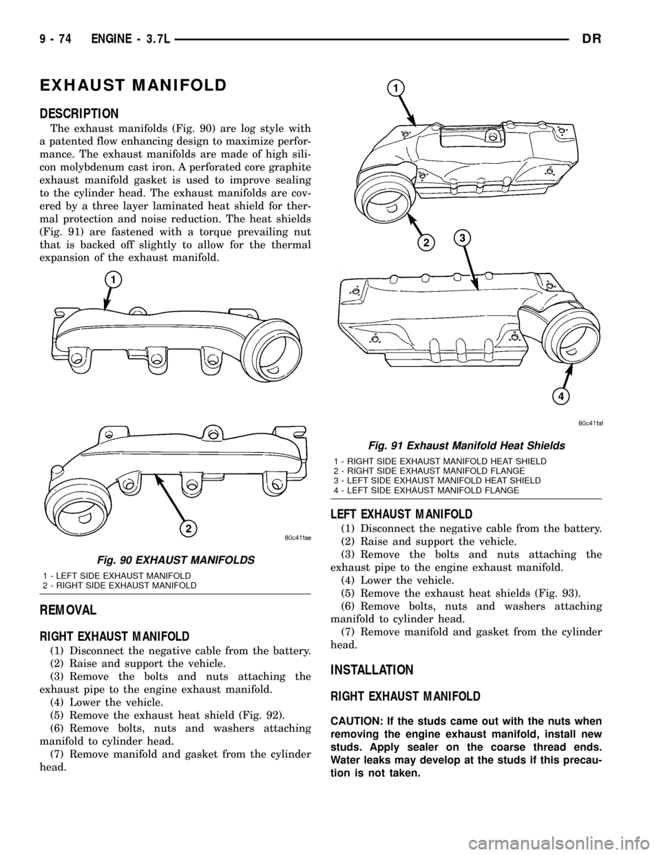
The exhaust manifolds (Fig. 90) are log style with
a patented flow enhancing design to maximize perfor-
mance. The exhaust manifolds are made of high sili-
con molybdenum cast iron. A perforated core graphite
exhaust manifold gasket is used to improve sealing
to the cylinder head. The exhaust manifolds are cov-
ered by a three layer laminated heat shield for ther-
mal protection and noise reduction. The heat shields
(Fig. 91) are fastened with a torque prevailing nut
that is backed off slightly to allow for the thermal
expansion of the exhaust manifold.
REMOVAL
RIGHT EXHAUST MANIFOLD
(1) Disconnect the negative cable from the battery.
(2) Raise and support the vehicle.
(3) Remove the bolts and nuts attaching the
exhaust pipe to the engine exhaust manifold.
(4) Lower the vehicle.
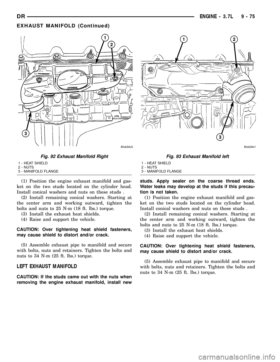
(5) Remove the exhaust heat shield (Fig. 92).
(6) Remove bolts, nuts and washers attaching
manifold to cylinder head.
(7) Remove manifold and gasket from the cylinder
head.
LEFT EXHAUST MANIFOLD
(1) Disconnect the negative cable from the battery.
(2) Raise and support the vehicle.
(3) Remove the bolts and nuts attaching the
exhaust pipe to the engine exhaust manifold.
(4) Lower the vehicle.
(5) Remove the exhaust heat shields (Fig. 93).
(6) Remove bolts, nuts and washers attaching
manifold to cylinder head.
(7) Remove manifold and gasket from the cylinder
head.
INSTALLATION
RIGHT EXHAUST MANIFOLD
CAUTION: If the studs came out with the nuts when
removing the engine exhaust manifold, install new
studs. Apply sealer on the coarse thread ends.
Water leaks may develop at the studs if this precau-
tion is not taken.
Fig. 90 EXHAUST MANIFOLDS
1 - LEFT SIDE EXHAUST MANIFOLD
2 - RIGHT SIDE EXHAUST MANIFOLD
Fig. 91 Exhaust Manifold Heat Shields
1 - RIGHT SIDE EXHAUST MANIFOLD HEAT SHIELD
2 - RIGHT SIDE EXHAUST MANIFOLD FLANGE
3 - LEFT SIDE EXHAUST MANIFOLD HEAT SHIELD
4 - LEFT SIDE EXHAUST MANIFOLD FLANGE
9 - 74 ENGINE - 3.7LDR
Page 1298 of 2627
(1) Position the engine exhaust manifold and gas-
ket on the two studs located on the cylinder head.
Install conical washers and nuts on these studs .
(2) Install remaining conical washers. Starting at
the center arm and working outward, tighten the
bolts and nuts to 25 N´m (18 ft. lbs.) torque.
(3) Install the exhaust heat shields.
(4) Raise and support the vehicle.
CAUTION: Over tightening heat shield fasteners,
may cause shield to distort and/or crack.
(5) Assemble exhaust pipe to manifold and secure
with bolts, nuts and retainers. Tighten the bolts and
nuts to 34 N´m (25 ft. lbs.) torque.
LEFT EXHAUST MANIFOLD
CAUTION: If the studs came out with the nuts when
removing the engine exhaust manifold, install newstuds. Apply sealer on the coarse thread ends.
Water leaks may develop at the studs if this precau-
tion is not taken.
(1) Position the engine exhaust manifold and gas-
ket on the two studs located on the cylinder head.
Install conical washers and nuts on these studs .
(2) Install remaining conical washers. Starting at
the center arm and working outward, tighten the
bolts and nuts to 25 N´m (18 ft. lbs.) torque.
(3) Install the exhaust heat shields.
(4) Raise and support the vehicle.
CAUTION: Over tightening heat shield fasteners,
may cause shield to distort and/or crack.
(5) Assemble exhaust pipe to manifold and secure
with bolts, nuts and retainers. Tighten the bolts and
nuts to 34 N´m (25 ft. lbs.) torque.
Fig. 92 Exhaust Manifold Right
1 - HEAT SHIELD
2 - NUTS
3 - MANIFOLD FLANGE
Fig. 93 Exhaust Manifold left
1 - HEAT SHIELD
2 - NUTS
3 - MANIFOLD FLANGE
DRENGINE - 3.7L 9 - 75
EXHAUST MANIFOLD (Continued)
Page 1301 of 2627
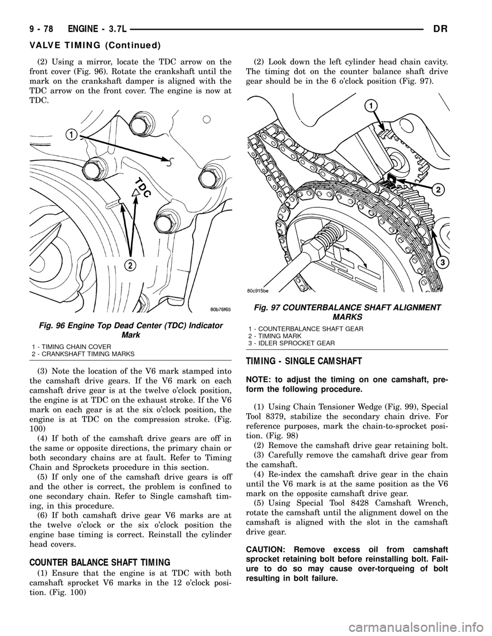
(2) Using a mirror, locate the TDC arrow on the
front cover (Fig. 96). Rotate the crankshaft until the
mark on the crankshaft damper is aligned with the
TDC arrow on the front cover. The engine is now at
TDC.
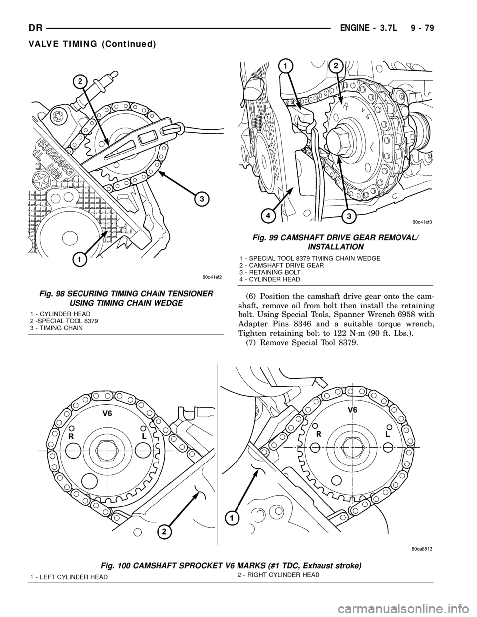
(3) Note the location of the V6 mark stamped into
the camshaft drive gears. If the V6 mark on each
camshaft drive gear is at the twelve o'clock position,
the engine is at TDC on the exhaust stroke. If the V6
mark on each gear is at the six o'clock position, the
engine is at TDC on the compression stroke. (Fig.
100)
(4) If both of the camshaft drive gears are off in
the same or opposite directions, the primary chain or
both secondary chains are at fault. Refer to Timing
Chain and Sprockets procedure in this section.
(5) If only one of the camshaft drive gears is off
and the other is correct, the problem is confined to
one secondary chain. Refer to Single camshaft tim-
ing, in this procedure.
(6) If both camshaft drive gear V6 marks are at
the twelve o'clock or the six o'clock position the
engine base timing is correct. Reinstall the cylinder
head covers.
COUNTER BALANCE SHAFT TIMING
(1) Ensure that the engine is at TDC with both
camshaft sprocket V6 marks in the 12 o'clock posi-
tion. (Fig. 100)(2) Look down the left cylinder head chain cavity.
The timing dot on the counter balance shaft drive
gear should be in the 6 o'clock position (Fig. 97).
TIMING - SINGLE CAMSHAFT
NOTE: to adjust the timing on one camshaft, pre-
form the following procedure.
(1) Using Chain Tensioner Wedge (Fig. 99), Special
Tool 8379, stabilize the secondary chain drive. For
reference purposes, mark the chain-to-sprocket posi-
tion. (Fig. 98)
(2) Remove the camshaft drive gear retaining bolt.
(3) Carefully remove the camshaft drive gear from
the camshaft.
(4) Re-index the camshaft drive gear in the chain
until the V6 mark is at the same position as the V6
mark on the opposite camshaft drive gear.
(5) Using Special Tool 8428 Camshaft Wrench,
rotate the camshaft until the alignment dowel on the
camshaft is aligned with the slot in the camshaft
drive gear.
CAUTION: Remove excess oil from camshaft
sprocket retaining bolt before reinstalling bolt. Fail-
ure to do so may cause over-torqueing of bolt
resulting in bolt failure.
Fig. 96 Engine Top Dead Center (TDC) Indicator
Mark
1 - TIMING CHAIN COVER
2 - CRANKSHAFT TIMING MARKS
Fig. 97 COUNTERBALANCE SHAFT ALIGNMENT
MARKS
1 - COUNTERBALANCE SHAFT GEAR
2 - TIMING MARK
3 - IDLER SPROCKET GEAR
9 - 78 ENGINE - 3.7LDR
VALVE TIMING (Continued)
Page 1302 of 2627
(6) Position the camshaft drive gear onto the cam-
shaft, remove oil from bolt then install the retaining
bolt. Using Special Tools, Spanner Wrench 6958 with
Adapter Pins 8346 and a suitable torque wrench,
Tighten retaining bolt to 122 N´m (90 ft. Lbs.).
(7) Remove Special Tool 8379.Fig. 98 SECURING TIMING CHAIN TENSIONER
USING TIMING CHAIN WEDGE
1 - CYLINDER HEAD
2 -SPECIAL TOOL 8379
3 - TIMING CHAIN
Fig. 99 CAMSHAFT DRIVE GEAR REMOVAL/
INSTALLATION
1 - SPECIAL TOOL 8379 TIMING CHAIN WEDGE
2 - CAMSHAFT DRIVE GEAR
3 - RETAINING BOLT
4 - CYLINDER HEAD
Fig. 100 CAMSHAFT SPROCKET V6 MARKS (#1 TDC, Exhaust stroke)
1 - LEFT CYLINDER HEAD2 - RIGHT CYLINDER HEAD
DRENGINE - 3.7L 9 - 79
VALVE TIMING (Continued)
Page 1306 of 2627

TIMING BELT/CHAIN AND
SPROCKETS
REMOVAL
(1) Disconnect negative cable from battery.
(2) Drain cooling system(Refer to 7 - COOLING -
STANDARD PROCEDURE).
(3) Remove right and left cylinder head covers(Re-
fer to 9 - ENGINE/CYLINDER HEAD/CYLINDER
HEAD COVER(S) - REMOVAL).
(4) Remove radiator fan shroud(Refer to 7 - COOL-
ING/ENGINE/RADIATOR FAN - REMOVAL).
(5) Rotate engine until timing mark on crankshaft
damper aligns with TDC mark on timing chain cover
(Fig. 108) and the camshaft sprocket ªV6º marks are
at the 12 o'clock position (No. 1 TDC exhaust stroke)
(Fig. 107).
(6) Remove power steering pump(Refer to 19 -
STEERING/PUMP - REMOVAL).
Fig. 107 CAMSHAFT SPROCKET V6 MARKS, (#1 TDC EXHAUST STROKE)
1 - LEFT CYLINDER HEAD2 - RIGHT CYLINDER HEAD
Fig. 108 Engine Top Dead Center
1 - TIMING CHAIN COVER
2 - CRANKSHAFT TIMING MARKS
DRENGINE - 3.7L 9 - 83