1998 DODGE RAM 1500 Exhaust
[x] Cancel search: ExhaustPage 1386 of 2627
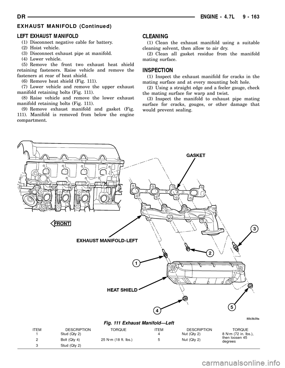
LEFT EXHAUST MANIFOLD
(1) Disconnect negative cable for battery.
(2) Hoist vehicle.
(3) Disconnect exhaust pipe at manifold.
(4) Lower vehicle.
(5) Remove the front two exhaust heat shield
retaining fasteners. Raise vehicle and remove the
fasteners at rear of heat shield.
(6) Remove heat shield (Fig. 111).
(7) Lower vehicle and remove the upper exhaust
manifold retaining bolts (Fig. 111).
(8) Raise vehicle and remove the lower exhaust
manifold retaining bolts (Fig. 111).
(9) Remove exhaust manifold and gasket (Fig.
111). Manifold is removed from below the engine
compartment.
CLEANING
(1) Clean the exhaust manifold using a suitable
cleaning solvent, then allow to air dry.
(2) Clean all gasket residue from the manifold
mating surface.
INSPECTION
(1) Inspect the exhaust manifold for cracks in the
mating surface and at every mounting bolt hole.
(2) Using a straight edge and a feeler gauge, check
the mating surface for warp and twist.
(3) Inspect the manifold to exhaust pipe mating
surface for cracks, gouges, or other damage that
would prevent sealing.
Fig. 111 Exhaust ManifoldÐLeft
ITEM DESCRIPTION TORQUE ITEM DESCRIPTION TORQUE
1 Stud (Qty 2)
25 N´m (18 ft. lbs.)4 Nut (Qty 2) 8 N´m (72 in. lbs.),
then loosen 45
degrees 2 Bolt (Qty 4) 5 Nut (Qty 2)
3 Stud (Qty 2)
DRENGINE - 4.7L 9 - 163
EXHAUST MANIFOLD (Continued)
Page 1387 of 2627
INSTALLATION
RIGHT EXHAUST MANIFOLD
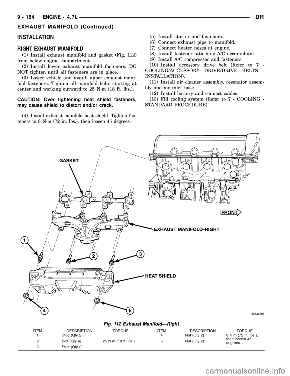
(1) Install exhaust manifold and gasket (Fig. 112)
from below engine compartment.
(2) Install lower exhaust manifold fasteners. DO
NOT tighten until all fasteners are in place.
(3) Lower vehicle and install upper exhaust mani-
fold fasteners. Tighten all manifold bolts starting at
center and working outward to 25 N´m (18 ft. lbs.).
CAUTION: Over tightening heat shield fasteners,
may cause shield to distort and/or crack.
(4)
Install exhaust manifold heat shield. Tighten fas-
teners to 8 N´m (72 in. lbs.), then loosen 45 degrees.
(5) Install starter and fasteners.
(6) Connect exhaust pipe to manifold.
(7) Connect heater hoses at engine.
(8) Install fastener attaching A/C accumulator.
(9) Install A/C compressor and fasteners.
(10) Install accessory drive belt (Refer to 7 -
COOLING/ACCESSORY DRIVE/DRIVE BELTS -
INSTALLATION).
(11) Install air cleaner assembly, resonator assem-
bly and air inlet hose.
(12) Install battery and connect cables.
(13) Fill cooling system (Refer to 7 - COOLING -
STANDARD PROCEDURE).
Fig. 112 Exhaust ManifoldÐRight
ITEM DESCRIPTION TORQUE ITEM DESCRIPTION TORQUE
1 Stud (Qty 2)
25 N´m (18 ft. lbs.)4 Nut (Qty 2) 8 N´m (72 in. lbs.),
then loosen 45
degrees 2 Bolt (Qty 4) 5 Nut (Qty 2)
3 Stud (Qty 2)
9 - 164 ENGINE - 4.7LDR
EXHAUST MANIFOLD (Continued)
Page 1388 of 2627
LEFT EXHAUST MANIFOLD
(1) Install exhaust manifold and gasket from below
engine compartment.
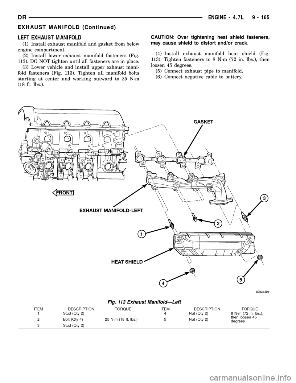
(2) Install lower exhaust manifold fasteners (Fig.
113). DO NOT tighten until all fasteners are in place.
(3) Lower vehicle and install upper exhaust mani-
fold fasteners (Fig. 113). Tighten all manifold bolts
starting at center and working outward to 25 N´m
(18 ft. lbs.).CAUTION: Over tightening heat shield fasteners,
may cause shield to distort and/or crack.
(4) Install exhaust manifold heat shield (Fig.
113). Tighten fasteners to 8 N´m (72 in. lbs.), then
loosen 45 degrees.
(5) Connect exhaust pipe to manifold.
(6) Connect negative cable to battery.
Fig. 113 Exhaust ManifoldÐLeft
ITEM DESCRIPTION TORQUE ITEM DESCRIPTION TORQUE
1 Stud (Qty 2)
25 N´m (18 ft. lbs.)4 Nut (Qty 2) 8 N´m (72 in. lbs.),
then loosen 45
degrees 2 Bolt (Qty 4) 5 Nut (Qty 2)
3 Stud (Qty 2)
DRENGINE - 4.7L 9 - 165
EXHAUST MANIFOLD (Continued)
Page 1391 of 2627
(2) Using a mirror, locate the TDC arrow on the
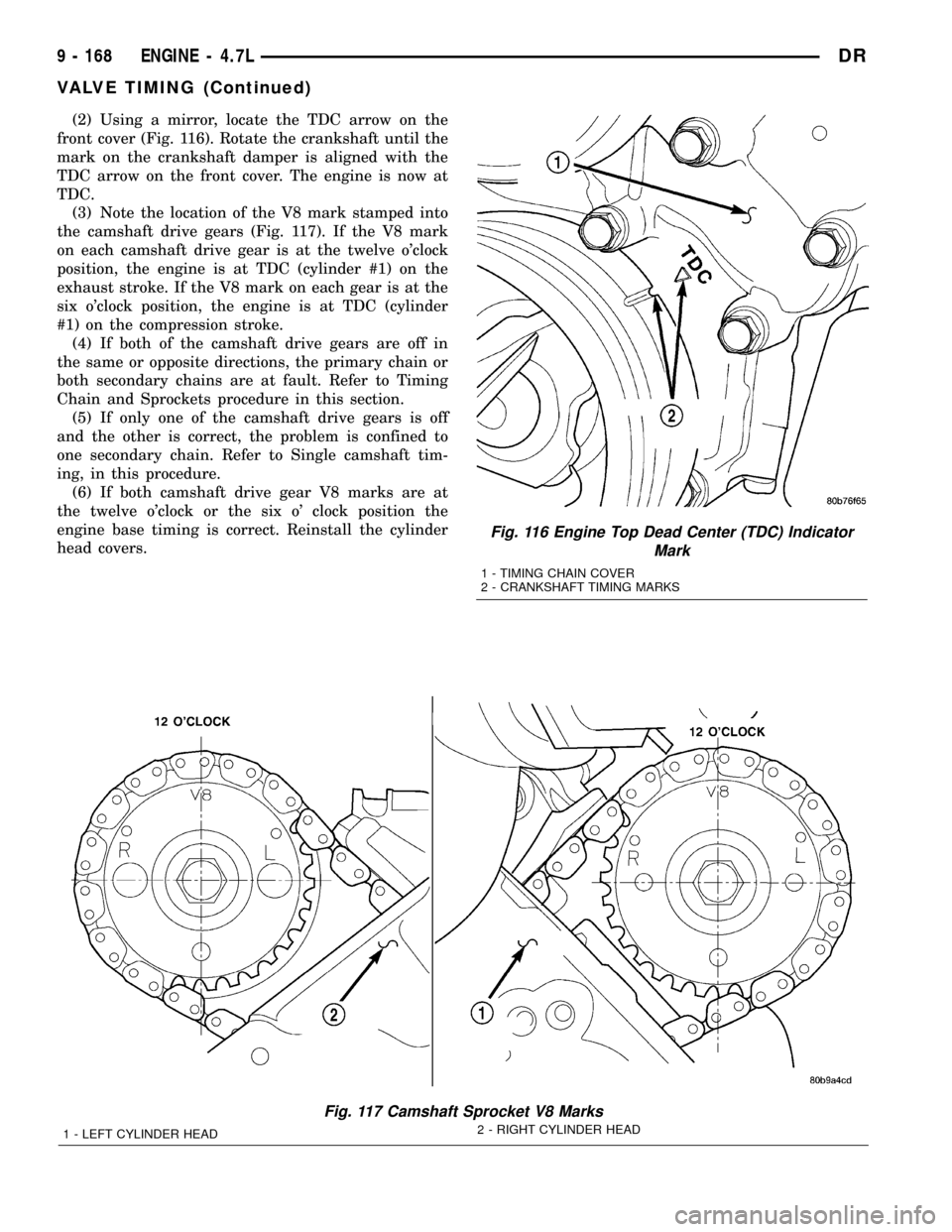
front cover (Fig. 116). Rotate the crankshaft until the
mark on the crankshaft damper is aligned with the
TDC arrow on the front cover. The engine is now at
TDC.
(3) Note the location of the V8 mark stamped into
the camshaft drive gears (Fig. 117). If the V8 mark
on each camshaft drive gear is at the twelve o'clock
position, the engine is at TDC (cylinder #1) on the
exhaust stroke. If the V8 mark on each gear is at the
six o'clock position, the engine is at TDC (cylinder
#1) on the compression stroke.
(4) If both of the camshaft drive gears are off in
the same or opposite directions, the primary chain or
both secondary chains are at fault. Refer to Timing
Chain and Sprockets procedure in this section.
(5) If only one of the camshaft drive gears is off
and the other is correct, the problem is confined to
one secondary chain. Refer to Single camshaft tim-
ing, in this procedure.
(6) If both camshaft drive gear V8 marks are at
the twelve o'clock or the six o' clock position the
engine base timing is correct. Reinstall the cylinder
head covers.
Fig. 116 Engine Top Dead Center (TDC) Indicator
Mark
1 - TIMING CHAIN COVER
2 - CRANKSHAFT TIMING MARKS
Fig. 117 Camshaft Sprocket V8 Marks
1 - LEFT CYLINDER HEAD2 - RIGHT CYLINDER HEAD
9 - 168 ENGINE - 4.7LDR
VALVE TIMING (Continued)
Page 1395 of 2627
(8) Install lower radiator hose.
(9) Install both heater hoses.
(10) Fill cooling system (Refer to 7 - COOLING -
STANDARD PROCEDURE).
(11) Connect the battery negative cable.
TIMING BELT/CHAIN AND
SPROCKETS
REMOVAL
(1) Disconnect negative cable from battery.
(2) Drain cooling system (Refer to 7 - COOLING -
STANDARD PROCEDURE).
(3) Remove right and left cylinder head covers
(Refer to 9 - ENGINE/CYLINDER HEAD/CYLIN-
DER HEAD COVER(S) - REMOVAL).
(4) Remove radiator fan shroud.
(5) Rotate engine until timing mark on crankshaft
damper aligns with TDC mark on timing chain cover
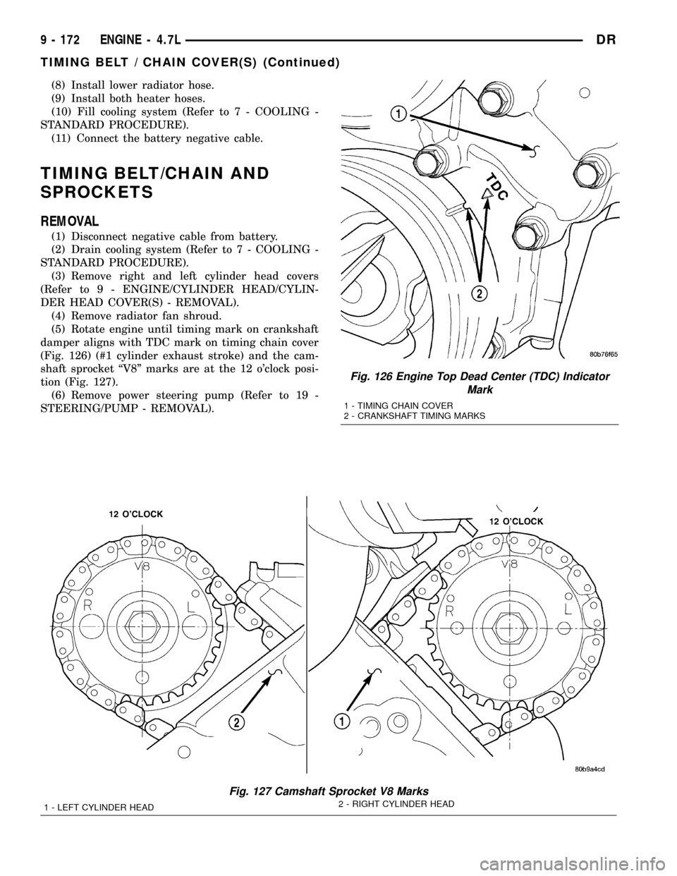
(Fig. 126) (#1 cylinder exhaust stroke) and the cam-
shaft sprocket ªV8º marks are at the 12 o'clock posi-
tion (Fig. 127).
(6) Remove power steering pump (Refer to 19 -
STEERING/PUMP - REMOVAL).
Fig. 126 Engine Top Dead Center (TDC) Indicator
Mark
1 - TIMING CHAIN COVER
2 - CRANKSHAFT TIMING MARKS
Fig. 127 Camshaft Sprocket V8 Marks
1 - LEFT CYLINDER HEAD2 - RIGHT CYLINDER HEAD
9 - 172 ENGINE - 4.7LDR
TIMING BELT / CHAIN COVER(S) (Continued)
Page 1403 of 2627
ENGINE - 5.7L
TABLE OF CONTENTS
page page
ENGINE - 5.7L
DESCRIPTION........................182
DIAGNOSIS AND TESTING
DIAGNOSIS AND TESTING - ENGINE
DIAGNOSIS - INTRODUCTION..........183
DIAGNOSIS AND TESTING - ENGINE
DIAGNOSIS - PERFORMANCE..........183
DIAGNOSIS AND TESTING - ENGINE
DIAGNOSIS - MECHANICAL............185
DIAGNOSIS AND TESTING - CYLINDER
COMPRESSION PRESSURE............186
DIAGNOSIS AND TESTING - CYLINDER
COMBUSTION PRESSURE LEAKAGE.....186
DIAGNOSIS AND TESTINGÐENGINE
DIAGNOSIS - LUBRICATION............187
DIAGNOSIS AND TESTING - ENGINE
DIAGNOSIS - MECHANICAL............188
STANDARD PROCEDURE
STANDARD PROCEDURE - REPAIR
DAMAGED OR WORN THREADS........190
STANDARD PROCEDUREÐHYDROSTATIC
LOCK..............................190
REMOVAL............................190
INSTALLATION........................191
SPECIFICATIONS
5.7L ENGINE........................192
TORQUE...........................195
SPECIAL TOOLS
5.7L ENGINE........................196
AIR INTAKE SYSTEM
REMOVAL............................199
INSTALLATION........................199
CYLINDER HEAD
OPERATIONÐCYLINDER HEAD...........199
DIAGNOSIS AND TESTINGÐCYLINDER HEAD
GASKET FAILURE....................199
REMOVAL............................200
CLEANING...........................200
INSPECTION.........................200
INSTALLATION........................200
CYLINDER HEAD COVER(S)
REMOVAL............................201
INSTALLATION........................201
INTAKE/EXHAUST VALVES & SEATS
DESCRIPTION
DESCRIPTION - VALVE GUIDES.........202
DESCRIPTION.......................202
STANDARD PROCEDURE - REFACING.....202
REMOVAL............................203INSTALLATION........................203
ROCKER ARM / ADJUSTER ASSY
REMOVAL............................203
INSTALLATION........................203
VALVE STEM SEALS
DESCRIPTION........................203
VALVE SPRINGS
REMOVAL............................204
INSTALLATION........................204
ENGINE BLOCK
CLEANING...........................205
INSPECTION.........................205
CAMSHAFT & BEARINGS (IN BLOCK)
REMOVAL
REMOVAL - CAMSHAFT CORE HOLE PLUG. 205
REMOVAL - CAMSHAFT...............205
INSPECTION.........................206
INSTALLATION
INSTALLATION - CAMSHAFT CORE HOLE
PLUG..............................206
INSTALLATION - CAMSHAFT............206
CRANKSHAFT
REMOVAL............................206
INSTALLATION........................207
CRANKSHAFT MAIN BEARINGS
STANDARD PROCEDURE - CRANKSHAFT
MAIN BEARING - FITTING..............207
INSPECTION.........................208
CRANKSHAFT OIL SEAL - FRONT
REMOVAL............................208
INSTALLATION........................208
CRANKSHAFT OIL SEAL - REAR
DIAGNOSIS AND TESTING - REAR SEAL
AREA LEAKS........................209
REMOVAL............................209
INSTALLATION........................209
CRANKSHAFT REAR OIL SEAL RETAINER
REMOVAL............................209
INSTALLATION........................210
FLEX PLATE
REMOVAL............................210
INSTALLATION........................210
HYDRAULIC TAPPETS
DIAGNOSIS AND TESTING - HYDRAULIC
TAPPETS...........................210
REMOVAL............................211
INSTALLATION........................211
PISTON & CONNECTING ROD
DESCRIPTION........................211
9 - 180 ENGINE - 5.7LDR
Page 1404 of 2627
STANDARD PROCEDUREÐPISTON FITTING . 211
REMOVAL............................212
CLEANING...........................212
INSPECTION.........................213
INSTALLATION........................213
PISTON RINGS
STANDARD PROCEDURE - PISTON RING
FITTING............................213
VIBRATION DAMPER
REMOVAL............................215
INSTALLATION........................215
STRUCTURAL COVER
DESCRIPTION........................216
OPERATION..........................216
REMOVAL............................216
INSTALLATION........................216
FRONT MOUNT
REMOVAL............................217
INSTALLATION........................218
REAR MOUNT
REMOVAL............................220
INSTALLATION........................220
LUBRICATION
DESCRIPTION........................220
DIAGNOSIS AND TESTING
DIAGNOSIS AND TESTING - CHECKING
ENGINE OIL PRESSURE...............220
DIAGNOSIS AND TESTING - ENGINE OIL
LEAK..............................220
OIL
STANDARD PROCEDURE - ENGINE OIL
SERVICE...........................222
OIL FILTER
REMOVAL............................223INSTALLATION........................223
OIL PAN
REMOVAL............................224
INSTALLATION........................224
OIL PUMP
REMOVAL............................224
CLEANING...........................224
INSPECTION.........................224
INSTALLATION........................225
INTAKE MANIFOLD
DESCRIPTION........................225
DIAGNOSIS AND TESTING - INTAKE
MANIFOLD LEAKAGE.................225
REMOVAL............................226
CLEANING...........................226
INSPECTION.........................226
INSTALLATION........................226
EXHAUST MANIFOLD
DESCRIPTION........................226
OPERATION..........................226
REMOVAL............................226
CLEANING...........................226
INSPECTION.........................227
INSTALLATION........................227
TIMING/CHAIN COVER
REMOVAL............................227
INSTALLATION........................227
TIMING/CHAIN AND SPROCKETS
REMOVAL............................228
INSTALLATION........................228
TIMING CHAIN/TENSIONER
DESCRIPTION........................229
OPERATION..........................229
DRENGINE - 5.7L 9 - 181
Page 1407 of 2627
CONDITION POSSIBLE CAUSE CORRECTION
ENGINE STALLS OR ROUGH IDLE 1. Idle speed set to low. 1. (Refer to 14 - FUEL SYSTEM/
FUEL INJECTION/IDLE AIR
CONTROL MOTOR - REMOVAL).
2. Idle mixture too lean or too rich. 2. Refer to Powertrain Diagnosis
Information.
3. Vacuum leak. 3. Inspect intake manifold and
vacuum hoses, repair or replace as
necessary.
4. Faulty coil. 4. (Refer to 8 - ELECTRICAL/
IGNITION CONTROL/IGNITION COIL
- REMOVAL).
5. Incorrect engine timing. 5. (Refer to 9 - ENGINE/VALVE
TIMING - STANDARD PROCEDURE).
1. ENGINE LOSS OF POWER 1. Dirty or incorrectly gapped spark
plugs.1. (Refer to 8 - ELECTRICAL/
IGNITION CONTROL/SPARK PLUG -
CLEANING).
2. Dirt or water in fuel system. 2. Clean system and replace fuel
filter.
3. Faulty fuel pump. 3. (Refer to 14 - FUEL SYSTEM/
FUEL DELIVERY/FUEL PUMP -
DIAGNOSIS AND TESTING).
4. Blown cylinder head gasket. 4. Replace cylinder head gasket.
5. Low compression. 5. (Refer to 9 - ENGINE -
DIAGNOSIS AND TESTING).
6. Burned, warped or pitted valves. 6. Replace as necessary.
7. Plugged or restricted exhaust
system.7. Inspect and replace as necessary.
8. Faulty coil. 8. (Refer to 8 - ELECTRICAL/
IGNITION CONTROL/IGNITION COIL
- REMOVAL).
1. ENGINE MISSES ON
ACCELERATION1. Spark plugs dirty or incorrectly
gapped.1. (Refer to 8 - ELECTRICAL/
IGNITION CONTROL/SPARK PLUG -
CLEANING).
2. Dirt in fuel system. 2. Clean fuel system.
3. Burned, warped or pitted valves. 3. Replcae as necessary.
4. Faulty coil. 4. (Refer to 8 - ELECTRICAL/
IGNITION CONTROL/IGNITION COIL
- REMOVAL).
1. ENGINE MISSES AT HIGH SPEED 1. Spark plugs dirty or incorrectly
gapped.1. (Refer to 8 - ELECTRICAL/
IGNITION CONTROL/SPARK PLUG -
CLEANING).
2. Faulty coil. 2. (Refer to 8 - ELECTRICAL/
IGNITION CONTROL/IGNITION COIL
- REMOVAL).
3. Dirt or water in fuel system. 3. Clean system and replace fuel
filter.
9 - 184 ENGINE - 5.7LDR
ENGINE - 5.7L (Continued)