1998 DODGE RAM 1500 Exhaust
[x] Cancel search: ExhaustPage 1348 of 2627
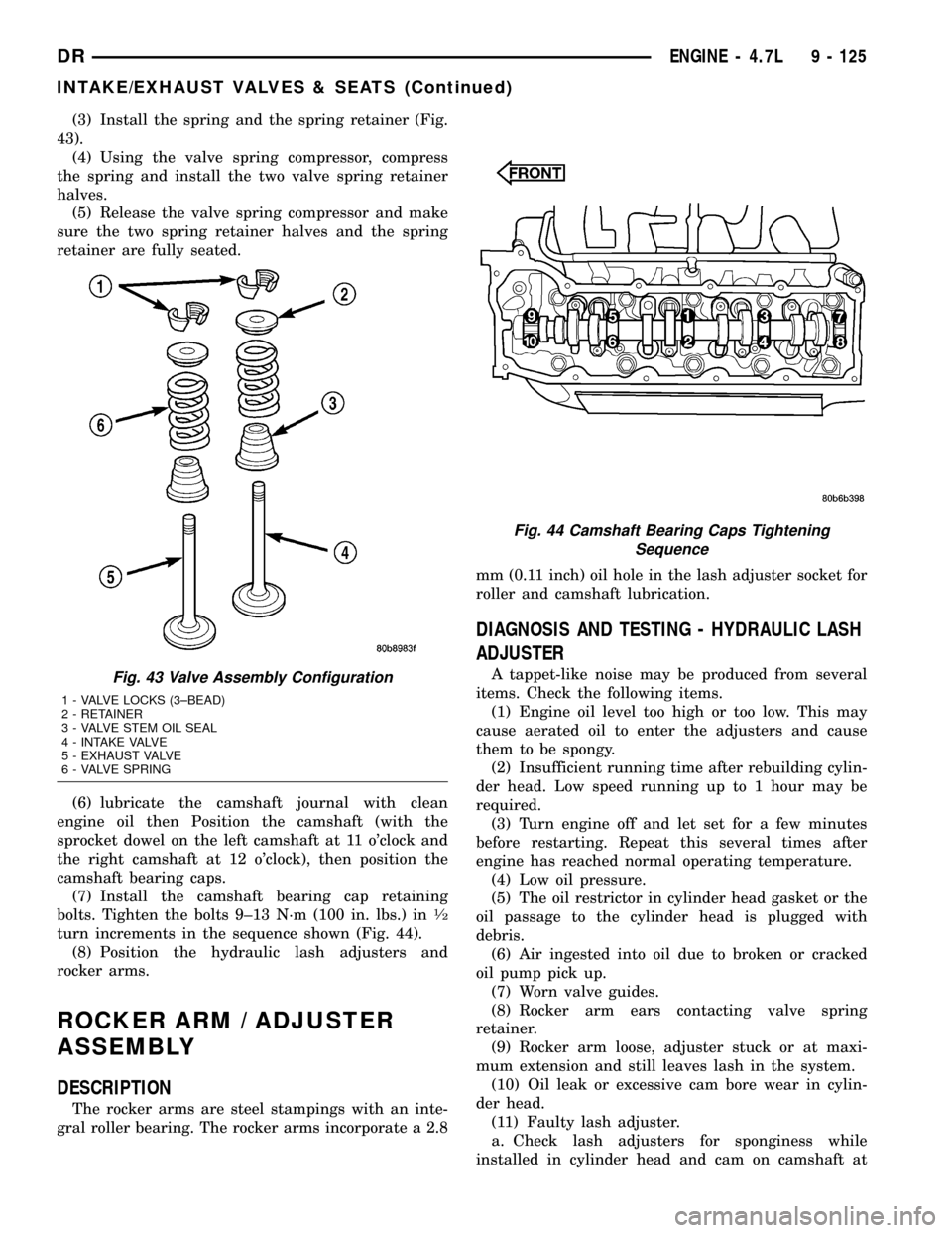
(3) Install the spring and the spring retainer (Fig.
43).
(4) Using the valve spring compressor, compress
the spring and install the two valve spring retainer
halves.
(5) Release the valve spring compressor and make
sure the two spring retainer halves and the spring
retainer are fully seated.
(6) lubricate the camshaft journal with clean
engine oil then Position the camshaft (with the
sprocket dowel on the left camshaft at 11 o'clock and
the right camshaft at 12 o'clock), then position the
camshaft bearing caps.
(7) Install the camshaft bearing cap retaining
bolts. Tighten the bolts 9±13 N´m (100 in. lbs.) in
1¤2
turn increments in the sequence shown (Fig. 44).
(8) Position the hydraulic lash adjusters and
rocker arms.
ROCKER ARM / ADJUSTER
ASSEMBLY
DESCRIPTION
The rocker arms are steel stampings with an inte-
gral roller bearing. The rocker arms incorporate a 2.8mm (0.11 inch) oil hole in the lash adjuster socket for
roller and camshaft lubrication.
DIAGNOSIS AND TESTING - HYDRAULIC LASH
ADJUSTER
A tappet-like noise may be produced from several
items. Check the following items.
(1) Engine oil level too high or too low. This may
cause aerated oil to enter the adjusters and cause
them to be spongy.
(2) Insufficient running time after rebuilding cylin-
der head. Low speed running up to 1 hour may be
required.
(3) Turn engine off and let set for a few minutes
before restarting. Repeat this several times after
engine has reached normal operating temperature.
(4) Low oil pressure.
(5) The oil restrictor in cylinder head gasket or the
oil passage to the cylinder head is plugged with
debris.
(6) Air ingested into oil due to broken or cracked
oil pump pick up.
(7) Worn valve guides.
(8) Rocker arm ears contacting valve spring
retainer.
(9) Rocker arm loose, adjuster stuck or at maxi-
mum extension and still leaves lash in the system.
(10) Oil leak or excessive cam bore wear in cylin-
der head.
(11) Faulty lash adjuster.
a. Check lash adjusters for sponginess while
installed in cylinder head and cam on camshaft atFig. 43 Valve Assembly Configuration
1 - VALVE LOCKS (3±BEAD)
2 - RETAINER
3 - VALVE STEM OIL SEAL
4 - INTAKE VALVE
5 - EXHAUST VALVE
6 - VALVE SPRING
Fig. 44 Camshaft Bearing Caps Tightening
Sequence
DRENGINE - 4.7L 9 - 125
INTAKE/EXHAUST VALVES & SEATS (Continued)
Page 1349 of 2627
base circle. Depress part of rocker arm over adjuster.
Normal adjusters should feel very firm. Spongy
adjusters can be bottomed out easily.
b. Remove suspected lash adjusters, and replace.
c. Before installation, make sure adjusters are at
least partially full of oil. This can be verified by little
or no plunger travel when lash adjuster is depressed.
REMOVAL
NOTE: Disconnect the battery negative cable to pre-
vent accidental starter engagement.
(1) Remove the cylinder head cover (Refer to 9 -
ENGINE/CYLINDER HEAD/CYLINDER HEAD
COVER(S) - REMOVAL).
(2) For rocker arm removal on cylinders 3 and 5
Rotate the crankshaft until cylinder #1 is at TDC
exhaust stroke.
(3) For rocker arm removal on cylinders 2 and 8
Rotate the crankshaft until cylinder #1 is at TDC
compression stroke.
(4) For rocker arm removal on cylinders 4 and 6
Rotate the crankshaft until cylinder #3 is at TDC
compression stroke.
(5) For rocker arm removal on cylinders 1 and 7
Rotate the crankshaft until cylinder #2 is at TDC
compression stroke.
(6) Using special tool 8516 Rocker Arm Remover,
press downward on the valve spring, remove rocker
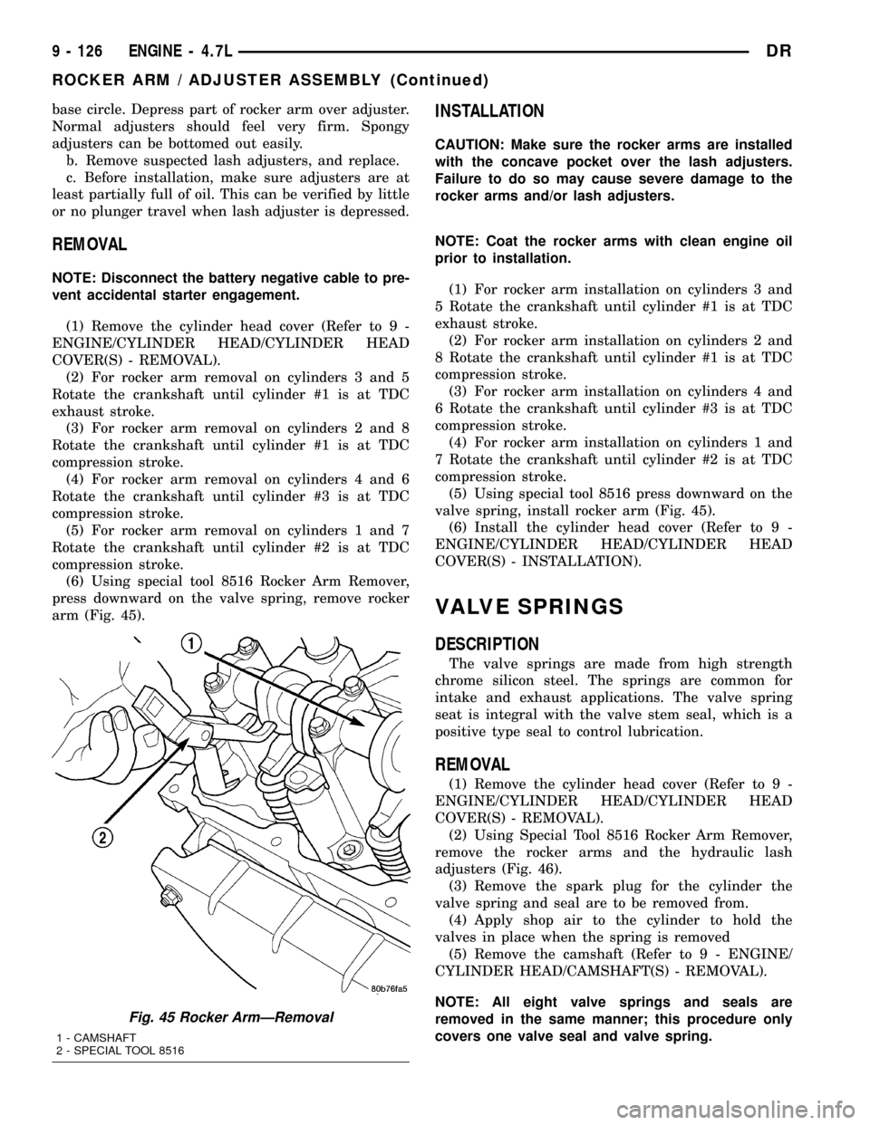
arm (Fig. 45).
INSTALLATION
CAUTION: Make sure the rocker arms are installed
with the concave pocket over the lash adjusters.
Failure to do so may cause severe damage to the
rocker arms and/or lash adjusters.
NOTE: Coat the rocker arms with clean engine oil
prior to installation.
(1) For rocker arm installation on cylinders 3 and
5 Rotate the crankshaft until cylinder #1 is at TDC
exhaust stroke.
(2) For rocker arm installation on cylinders 2 and
8 Rotate the crankshaft until cylinder #1 is at TDC
compression stroke.
(3) For rocker arm installation on cylinders 4 and
6 Rotate the crankshaft until cylinder #3 is at TDC
compression stroke.
(4) For rocker arm installation on cylinders 1 and
7 Rotate the crankshaft until cylinder #2 is at TDC
compression stroke.
(5) Using special tool 8516 press downward on the
valve spring, install rocker arm (Fig. 45).
(6) Install the cylinder head cover (Refer to 9 -
ENGINE/CYLINDER HEAD/CYLINDER HEAD
COVER(S) - INSTALLATION).
VALVE SPRINGS
DESCRIPTION
The valve springs are made from high strength
chrome silicon steel. The springs are common for
intake and exhaust applications. The valve spring
seat is integral with the valve stem seal, which is a
positive type seal to control lubrication.
REMOVAL
(1) Remove the cylinder head cover (Refer to 9 -
ENGINE/CYLINDER HEAD/CYLINDER HEAD
COVER(S) - REMOVAL).
(2) Using Special Tool 8516 Rocker Arm Remover,
remove the rocker arms and the hydraulic lash
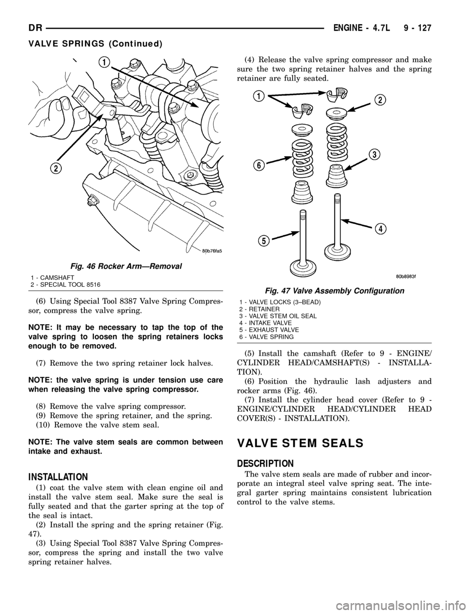
adjusters (Fig. 46).
(3) Remove the spark plug for the cylinder the
valve spring and seal are to be removed from.
(4) Apply shop air to the cylinder to hold the
valves in place when the spring is removed
(5) Remove the camshaft (Refer to 9 - ENGINE/
CYLINDER HEAD/CAMSHAFT(S) - REMOVAL).
NOTE: All eight valve springs and seals are
removed in the same manner; this procedure only
covers one valve seal and valve spring.
Fig. 45 Rocker ArmÐRemoval
1 - CAMSHAFT
2 - SPECIAL TOOL 8516
9 - 126 ENGINE - 4.7LDR
ROCKER ARM / ADJUSTER ASSEMBLY (Continued)
Page 1350 of 2627
(6) Using Special Tool 8387 Valve Spring Compres-
sor, compress the valve spring.
NOTE: It may be necessary to tap the top of the
valve spring to loosen the spring retainers locks
enough to be removed.
(7) Remove the two spring retainer lock halves.
NOTE: the valve spring is under tension use care
when releasing the valve spring compressor.
(8) Remove the valve spring compressor.
(9) Remove the spring retainer, and the spring.
(10) Remove the valve stem seal.
NOTE: The valve stem seals are common between
intake and exhaust.
INSTALLATION
(1) coat the valve stem with clean engine oil and
install the valve stem seal. Make sure the seal is
fully seated and that the garter spring at the top of
the seal is intact.
(2) Install the spring and the spring retainer (Fig.
47).
(3) Using Special Tool 8387 Valve Spring Compres-
sor, compress the spring and install the two valve
spring retainer halves.(4) Release the valve spring compressor and make
sure the two spring retainer halves and the spring
retainer are fully seated.
(5) Install the camshaft (Refer to 9 - ENGINE/
CYLINDER HEAD/CAMSHAFT(S) - INSTALLA-
TION).
(6) Position the hydraulic lash adjusters and
rocker arms (Fig. 46).
(7) Install the cylinder head cover (Refer to 9 -
ENGINE/CYLINDER HEAD/CYLINDER HEAD
COVER(S) - INSTALLATION).
VALVE STEM SEALS
DESCRIPTION
The valve stem seals are made of rubber and incor-
porate an integral steel valve spring seat. The inte-
gral garter spring maintains consistent lubrication
control to the valve stems.
Fig. 46 Rocker ArmÐRemoval
1 - CAMSHAFT
2 - SPECIAL TOOL 8516
Fig. 47 Valve Assembly Configuration
1 - VALVE LOCKS (3±BEAD)
2 - RETAINER
3 - VALVE STEM OIL SEAL
4 - INTAKE VALVE
5 - EXHAUST VALVE
6 - VALVE SPRING
DRENGINE - 4.7L 9 - 127
VALVE SPRINGS (Continued)
Page 1368 of 2627
(9) Install accessory drive belt (Refer to 7 - COOL-
ING/ACCESSORY DRIVE/DRIVE BELTS - INSTAL-
LATION).
(10) Refill cooling system (Refer to 7 - COOLING -
STANDARD PROCEDURE).
(11) Connect negative cable to battery.
STRUCTURAL COVER
DESCRIPTION
The structural dust cover is made of die cast alu-
minum and joins the lower half of the transmission
bell housing to the engine bedplate.
OPERATION
The structural cover provides additional power-
train stiffness and reduces noise and vibration.
REMOVAL
(1) Raise vehicle on hoist.
(2) Remove the left hand exhaust pipe from
exhaust manifold.
(3) Loosen the right hand exhaust manifold-to-ex-
haust pipe retaining bolts.
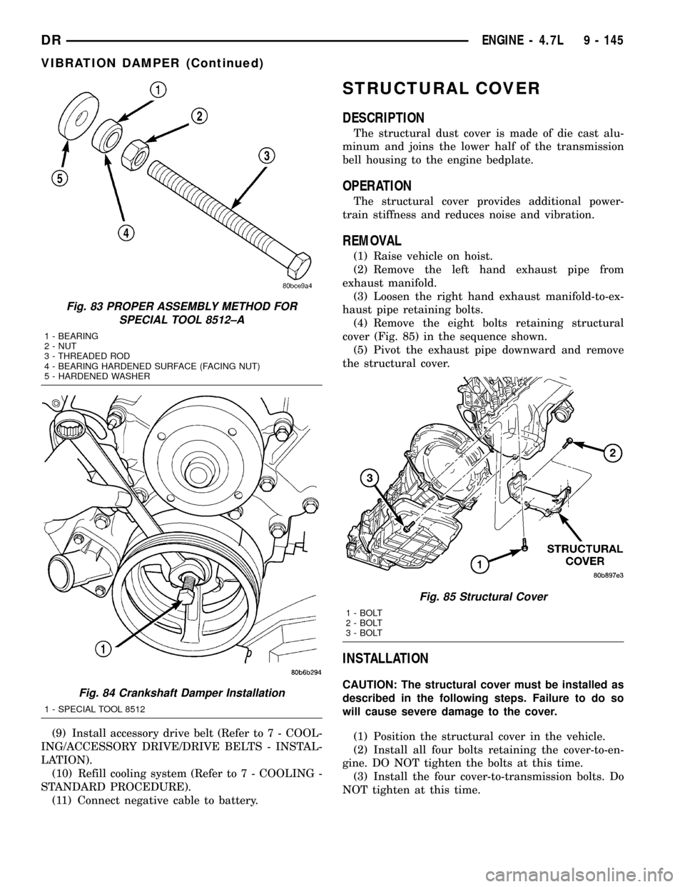
(4) Remove the eight bolts retaining structural
cover (Fig. 85) in the sequence shown.
(5) Pivot the exhaust pipe downward and remove
the structural cover.
INSTALLATION
CAUTION: The structural cover must be installed as
described in the following steps. Failure to do so
will cause severe damage to the cover.
(1) Position the structural cover in the vehicle.
(2) Install all four bolts retaining the cover-to-en-
gine. DO NOT tighten the bolts at this time.
(3) Install the four cover-to-transmission bolts. Do
NOT tighten at this time.
Fig. 83 PROPER ASSEMBLY METHOD FOR
SPECIAL TOOL 8512±A
1 - BEARING
2 - NUT
3 - THREADED ROD
4 - BEARING HARDENED SURFACE (FACING NUT)
5 - HARDENED WASHER
Fig. 84 Crankshaft Damper Installation
1 - SPECIAL TOOL 8512
Fig. 85 Structural Cover
1 - BOLT
2 - BOLT
3 - BOLT
DRENGINE - 4.7L 9 - 145
VIBRATION DAMPER (Continued)
Page 1369 of 2627
CAUTION: The structural cover must be held tightly
against both the engine and the transmission bell
housing during tightening sequence. Failure to do
so may cause damage to the cover.
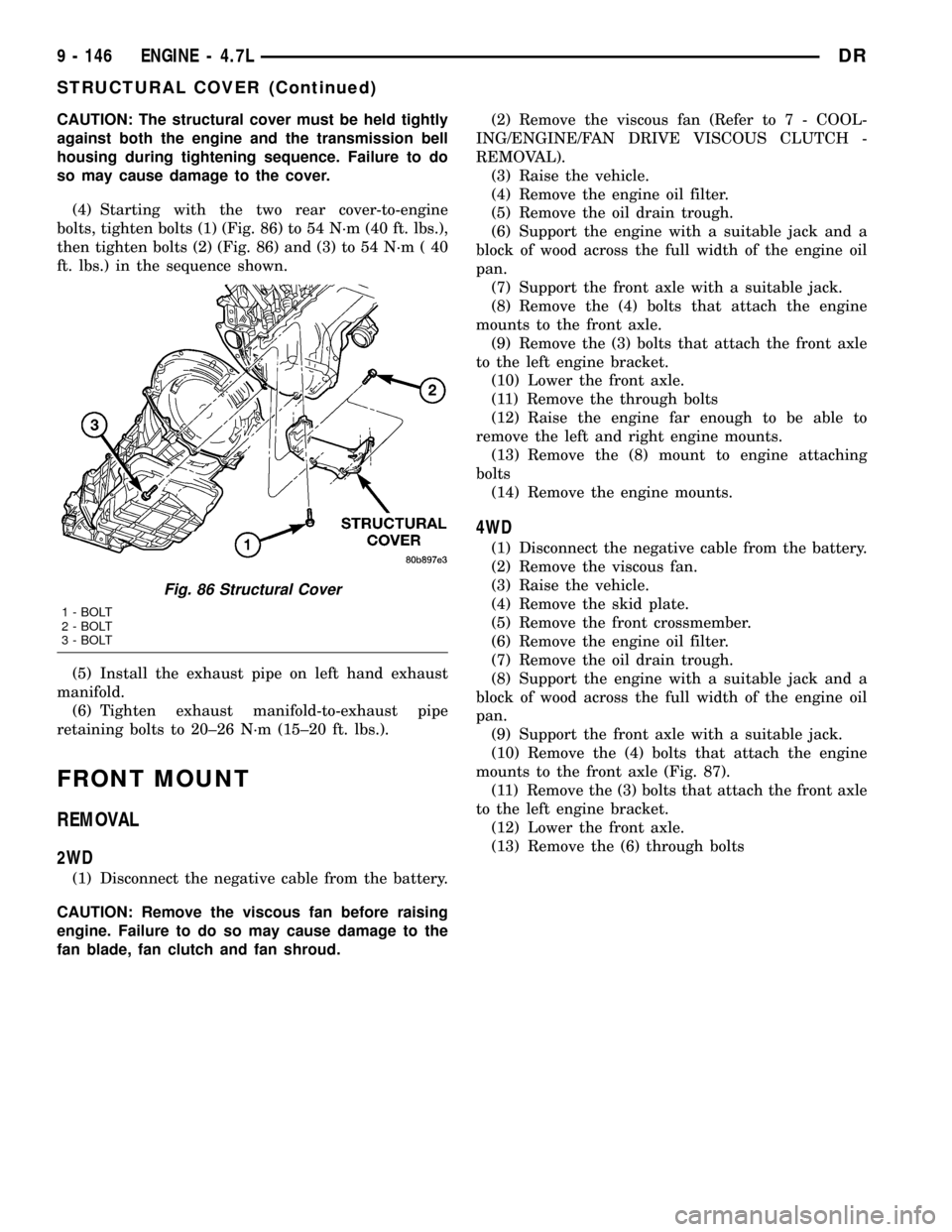
(4) Starting with the two rear cover-to-engine
bolts, tighten bolts (1) (Fig. 86) to 54 N´m (40 ft. lbs.),
then tighten bolts (2) (Fig. 86) and (3) to 54 N´m ( 40
ft. lbs.) in the sequence shown.
(5) Install the exhaust pipe on left hand exhaust
manifold.
(6) Tighten exhaust manifold-to-exhaust pipe
retaining bolts to 20±26 N´m (15±20 ft. lbs.).
FRONT MOUNT
REMOVAL
2WD
(1) Disconnect the negative cable from the battery.
CAUTION: Remove the viscous fan before raising
engine. Failure to do so may cause damage to the
fan blade, fan clutch and fan shroud.(2) Remove the viscous fan (Refer to 7 - COOL-
ING/ENGINE/FAN DRIVE VISCOUS CLUTCH -
REMOVAL).
(3) Raise the vehicle.
(4) Remove the engine oil filter.
(5) Remove the oil drain trough.
(6) Support the engine with a suitable jack and a
block of wood across the full width of the engine oil
pan.
(7) Support the front axle with a suitable jack.
(8) Remove the (4) bolts that attach the engine
mounts to the front axle.
(9) Remove the (3) bolts that attach the front axle
to the left engine bracket.
(10) Lower the front axle.
(11) Remove the through bolts
(12) Raise the engine far enough to be able to
remove the left and right engine mounts.
(13) Remove the (8) mount to engine attaching
bolts
(14) Remove the engine mounts.
4WD
(1) Disconnect the negative cable from the battery.
(2) Remove the viscous fan.
(3) Raise the vehicle.
(4) Remove the skid plate.
(5) Remove the front crossmember.
(6) Remove the engine oil filter.
(7) Remove the oil drain trough.
(8) Support the engine with a suitable jack and a
block of wood across the full width of the engine oil
pan.
(9) Support the front axle with a suitable jack.
(10) Remove the (4) bolts that attach the engine
mounts to the front axle (Fig. 87).
(11) Remove the (3) bolts that attach the front axle
to the left engine bracket.
(12) Lower the front axle.
(13) Remove the (6) through bolts
Fig. 86 Structural Cover
1 - BOLT
2 - BOLT
3 - BOLT
9 - 146 ENGINE - 4.7LDR
STRUCTURAL COVER (Continued)
Page 1374 of 2627
The camshaft exhaust valve lobes and rocker arms
are lubricated through a small hole in the rocker
arm; oil flows through the lash adjuster then through
the rocker arm and onto the camshaft lobe. Due to
the orentation of the rocker arm, the camshaft intake
lobes are not lubed in the same manner as the
exhaust lobes. The intake lobes are lubed through
internal passages in the camshaft. Oil flows througha bore in the number 3 camshaft bearing bore, and
as the camshaft turns, a hole in the camshaft aligns
with the hole in the camshaft bore allowing engine
oil to enter the camshaft tube. The oil then exits
through 1.6mm (0.063 in.) holes drilled into the
intake lobes, lubricating the lobes and the rocker
arms.
ENGINE LUBRICATION FLOW CHARTÐBLOCK: TABLE 1
FROM TO
Oil Pickup Tube Oil Pump
Oil Pump Oil Filter
Oil Filter Block Main Oil Gallery
Block Main Oil Gallery 1. Crankshaft Main Journal
2. Left Cylinder Head*
3. Right Cylinder Head*
Crankshaft Main Journals Crankshaft Rod Journals
Crankshaft Number One Main Journal 1.Front Timing Chain Idler Shaft
2.Both Secondary Chain Tensioners
Left Cylinder Head See Table 2
Right Cylinder Head See Table 2
* The cylinder head gaskets have an oil restricter to control oil flow to the cylinder heads.
ENGINE LUBRICATION FLOW CHARTÐCYLINDER HEADS: TABLE 2
FROM TO
Cylinder Head Oil Port (in bolt hole) Diagonal Cross Drilling to Main Oil Gallery
Main Oil Gallery (drilled through head from rear to
front)1. Base of Camshaft Towers
2. Lash Adjuster Towers
Base of Camshaft Towers Vertical Drilling Through Tower to Camshaft Bearings**
Lash Adjuster Towers Diagonal Drillings to Hydraulic Lash Adjuster Pockets
** The number three camshaft bearing journal feeds oil into the hollow camshaft tubes. Oil is routed to the intake
lobes, which have oil passages drilled into them to lubricate the rocker arms.
DRENGINE - 4.7L 9 - 151
LUBRICATION (Continued)
Page 1384 of 2627
EXHAUST MANIFOLD
DESCRIPTION
The exhaust manifolds are log style with a pat-
ented flow enhancing design to maximize perfor-
mance. The exhaust manifolds are made of high
silicon molybdenum cast iron. A perforated core
graphite exhaust manifold gasket is used to improve
sealing to the cylinder head. The exhaust manifolds
are covered by a three layer laminated heat shield
for thermal protection and noise reduction. The heat
shields are fastened with a torque prevailing nut
that is backed off slightly to allow for the thermal
expansion of the exhaust manifold.
REMOVAL
RIGHT EXHAUST MANIFOLD
(1) Disconnect negative cable for battery.
(2) Remove air cleaner assembly, resonator assem-
bly and air inlet hose.
(3) Remove accessory drive belt (Refer to 7 -
COOLING/ACCESSORY DRIVE/DRIVE BELTS -
REMOVAL).
(4) Remove A/C compressor (Refer to 24 - HEAT-
ING & AIR CONDITIONING/PLUMBING/A/C COM-
PRESSOR - REMOVAL).
(5) Remove A/C accumulator support bracket fas-
tener.(6) Drain coolant below heater hose level (Refer to
7 - COOLING - STANDARD PROCEDURE).
(7) Remove heater hoses at engine.
(8) Remove fasteners attaching exhaust manifold
heat shield.
(9) Remove heat shield.
(10) Remove upper exhaust manifold attaching fas-
teners.
(11) Raise vehicle on hoist.
(12) Disconnect exhaust pipe from manifold.
(13) Remove fasteners attaching starter. Move
starter aside.
(14) Remove lower exhaust manifold attaching fas-
teners.
(15) Remove exhaust manifold and gasket (Fig.
110). Manifold is removed from below the engine
compartment.
DRENGINE - 4.7L 9 - 161
Page 1385 of 2627
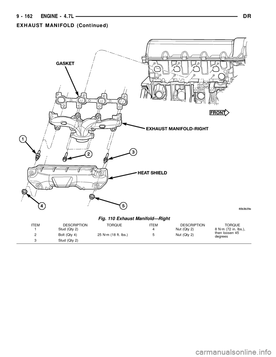
Fig. 110 Exhaust ManifoldÐRight
ITEM DESCRIPTION TORQUE ITEM DESCRIPTION TORQUE
1 Stud (Qty 2)
25 N´m (18 ft. lbs.)4 Nut (Qty 2) 8 N´m (72 in. lbs.),
then loosen 45
degrees 2 Bolt (Qty 4) 5 Nut (Qty 2)
3 Stud (Qty 2)
9 - 162 ENGINE - 4.7LDR
EXHAUST MANIFOLD (Continued)