1998 DODGE RAM 1500 Exhaust
[x] Cancel search: ExhaustPage 502 of 2627

Knock sensors contain a piezoelectric material
which constantly vibrates and sends an input voltage
(signal) to the PCM while the engine operates. As the
intensity of the crystal's vibration increases, the
knock sensor output voltage also increases.
The voltage signal produced by the knock sensor
increases with the amplitude of vibration. The PCM
receives the knock sensor voltage signal as an input.
If the signal rises above a predetermined level, the
PCM will store that value in memory and retard
ignition timing to reduce engine knock. If the knock
sensor voltage exceeds a preset value, the PCM
retards ignition timing for all cylinders. It is not a
selective cylinder retard.
The PCM ignores knock sensor input during engine
idle conditions. Once the engine speed exceeds a
specified value, knock retard is allowed.
Knock retard uses its own short term and long
term memory program.
Long term memory stores previous detonation
information in its battery-backed RAM. The maxi-
mum authority that long term memory has over tim-
ing retard can be calibrated.
Short term memory is allowed to retard timing up
to a preset amount under all operating conditions (as
long as rpm is above the minimum rpm) except at
Wide Open Throttle (WOT). The PCM, using short
term memory, can respond quickly to retard timing
when engine knock is detected. Short term memory
is lost any time the ignition key is turned off.
NOTE: Over or under tightening the sensor mount-
ing bolts will affect knock sensor performance, pos-
sibly causing improper spark control. Always use
the specified torque when installing the knock sen-
sors.
REMOVAL
3.7L V-6 / 4.7L V-8
The 2 knock sensors are bolted into the cylinder
block under the intake manifold (Fig. 20). or (Fig.
21).
NOTE: The left sensor is identified by an identifica-
tion tag (LEFT). It is also identified by a larger bolt
head. The Powertrain Control Module (PCM) must
have and know the correct sensor left/right posi-
tions. Do not mix the sensor locations.
(1) Disconnect knock sensor dual pigtail harness
from engine wiring harness. This connection is made
near rear of engine.
(2) Remove intake manifold. Refer to Engine sec-
tion.(3) Remove sensor mounting bolts (Fig. 20), or
(Fig. 21). Note foam strip on bolt threads. This foam
is used only to retain the bolts to sensors for plant
assembly. It is not used as a sealant. Do not apply
any adhesive, sealant or thread locking compound to
these bolts.
(4) Remove sensors from engine.
5.7L V8
Two sensors are used. Each sensor is bolted into
the outside of cylinder block below the exhaust man-
ifold (Fig. 22).
(1) Raise vehicle.
(2) Disconnect knock sensor electrical connector.
(3) Remove sensor mounting bolt (Fig. 22). Note
foam strip on bolt threads. This foam is used only to
retain the bolts to sensors for plant assembly. It is
not used as a sealant. Do not apply any adhesive,
sealant or thread locking compound to these bolts.
(4) Remove sensor from engine.
INSTALLATION
3.7L V-6 / 4.7L V-8
NOTE: The left sensor is identified by an identifica-
tion tag (LEFT). It is also identified by a larger bolt
head. The Powertrain Control Module (PCM) must
have and know the correct sensor left/right posi-
tions. Do not mix the sensor locations.
Fig. 20 KNOCK SENSOR Ð 3.7L V-6
1 - KNOCK SENSORS (2)
2 - MOUNTING BOLTS
DRIGNITION CONTROL 8I - 15
KNOCK SENSOR (Continued)
Page 503 of 2627

(1) Thoroughly clean knock sensor mounting holes.
(2) Install sensors into cylinder block.
NOTE: Over or under tightening the sensor mount-
ing bolts will affect knock sensor performance, pos-
sibly causing improper spark control. Always use
the specified torque when installing the knock sen-
sors. The torque for the knock senor bolt is rela-
tively light for an 8mm bolt.
NOTE: Note foam strip on bolt threads. This foam is
used only to retain the bolts to sensors for plant
assembly. It is not used as a sealant. Do not apply
any adhesive, sealant or thread locking compound
to these bolts.
(3) Install and tighten mounting bolts. Refer to
torque specification.
(4) Install intake manifold. Refer to Engine sec-
tion.
(5) Connect knock sensor wiring harness to engine
harness at rear of intake manifold.
5.7L V-8
(1) Thoroughly clean knock sensor mounting hole.
(2) Install sensor into cylinder block.
NOTE: Over or under tightening the sensor mount-
ing bolts will affect knock sensor performance, pos-
sibly causing improper spark control. Always use
the specified torque when installing the knock sen-
sors. The torque for the knock senor bolt is rela-
tively light for an 8mm bolt.
NOTE: Note foam strip on bolt threads. This foam is
used only to retain the bolts to sensors for plant
assembly. It is not used as a sealant. Do not apply
any adhesive, sealant or thread locking compound
to these bolts.
(3) Install and tighten mounting bolt. Refer to
torque specification.
(4) Install electrical connector to sensor.
Fig. 21 KNOCK SENSOR Ð 4.7L V-8
1 - KNOCK SENSORS (2)
2 - MOUNTING BOLTS
3 - INTAKE MANIFOLD (CUTAWAY)
4 - PIGTAIL CONNECTOR
Fig. 22 5.7L KNOCK SENSOR (RIGHT SENSOR
SHOWN)
1 - KNOCK SENSOR (RIGHT SENSOR SHOWN)
2 - MOUNTING BOLT
3 - EXHAUST MANIFOLD
4 - RIGHT ENGINE MOUNT
5 - ELEC. CONNECTOR
8I - 16 IGNITION CONTROLDR
KNOCK SENSOR (Continued)
Page 734 of 2627

DESCRIPTION - CONNECTOR, GROUND AND
SPLICE INFORMATION
CAUTION: Not all connectors are serviced. Some
connectors are serviced only with a harness. A typ-
ical example might be the Supplemental Restraint
System connectors. Always check parts availability
before attempting a repair.
IDENTIFICATION
In-line connectors are identified by a number, as
follows:
²In-line connectors located in the engine compart-
ment are C100 series numbers
²In-line connectors located in the Instrument
Panel area are C200 series numbers.
²In-line connectors located in the body are C300
series numbers.
²Jumper harness connectors are C400 series
numbers.
²Grounds and ground connectors are identified
with a ªGº and follow the same series numbering as
the in-line connectors.
²Splices are identified with an ªSº and follow the
same series numbering as the in-line connectors.
²Component connectors are identified by the com-
ponent name instead of a number. Multiple connec-
tors on a component use a C1, C2, etc. identifier.
LOCATIONS
Section 8W-91 contains connector/ground/splice
location illustrations. The illustrations contain the
connector name (or number)/ground number/splice
number and component identification. Connector/
ground/splice location charts in section 8W-91 refer-
ence the figure numbers of the illustrations.
The abbreviation T/O is used in the component
location section to indicate a point in which the wir-
ing harness branches out to a component. The abbre-
viation N/S means Not Shown in the illustrations
WARNING
WARNINGS - GENERAL
WARNINGSprovide information to prevent per-
sonal injury and vehicle damage. Below is a list of
general warnings that should be followed any time a
vehicle is being serviced.
WARNING: ALWAYS WEAR SAFETY GLASSES FOR
EYE PROTECTION.
WARNING: USE SAFETY STANDS ANYTIME A PRO-
CEDURE REQUIRES BEING UNDER A VEHICLE.WARNING: BE SURE THAT THE IGNITION SWITCH
ALWAYS IS IN THE OFF POSITION, UNLESS THE
PROCEDURE REQUIRES IT TO BE ON.
WARNING: SET THE PARKING BRAKE WHEN
WORKING ON ANY VEHICLE. AN AUTOMATIC
TRANSMISSION SHOULD BE IN PARK. A MANUAL
TRANSMISSION SHOULD BE IN NEUTRAL.
WARNING: OPERATE THE ENGINE ONLY IN A
WELL-VENTILATED AREA.
WARNING: KEEP AWAY FROM MOVING PARTS
WHEN THE ENGINE IS RUNNING, ESPECIALLY THE
FAN AND BELTS.
WARNING: TO PREVENT SERIOUS BURNS, AVOID
CONTACT WITH HOT PARTS SUCH AS THE RADIA-
TOR, EXHAUST MANIFOLD(S), TAIL PIPE, CATA-
LYTIC CONVERTER AND MUFFLER.
WARNING: DO NOT ALLOW FLAME OR SPARKS
NEAR THE BATTERY. GASES ARE ALWAYS
PRESENT IN AND AROUND THE BATTERY.
WARNING: ALWAYS REMOVE RINGS, WATCHES,
LOOSE HANGING JEWELRY AND AVOID LOOSE
CLOTHING.
DIAGNOSIS AND TESTING - WIRING HARNESS
TROUBLESHOOTING TOOLS
When diagnosing a problem in an electrical circuit
there are several common tools necessary. These tools
are listed and explained below.
²Jumper Wire - This is a test wire used to con-
nect two points of a circuit. It can be used to bypass
an open in a circuit.
WARNING: NEVER USE A JUMPER WIRE ACROSS
A LOAD, SUCH AS A MOTOR, CONNECTED
BETWEEN A BATTERY FEED AND GROUND.
²Voltmeter - Used to check for voltage on a cir-
cuit. Always connect the black lead to a known good
ground and the red lead to the positive side of the
circuit.
CAUTION: Most of the electrical components used
in today's vehicles are Solid State. When checking
voltages in these circuits, use a meter with a 10 -
megohm or greater impedance rating.
DR8W-01 WIRING DIAGRAM INFORMATION 8W - 01 - 7
WIRING DIAGRAM INFORMATION (Continued)
Page 1224 of 2627

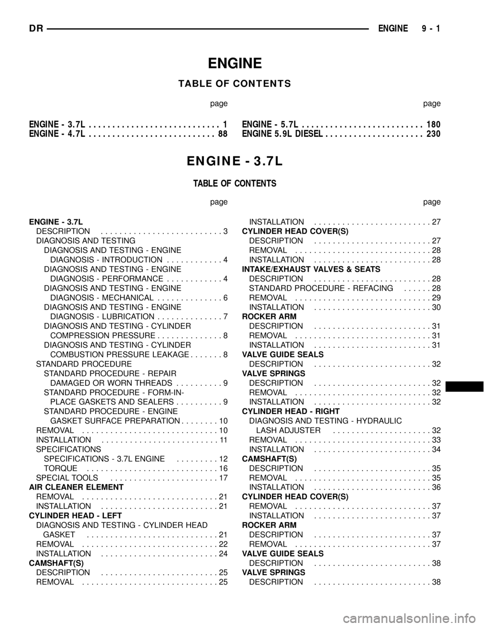
ENGINE
TABLE OF CONTENTS
page page
ENGINE - 3.7L............................ 1
ENGINE - 4.7L........................... 88ENGINE - 5.7L.......................... 180
ENGINE 5.9L DIESEL..................... 230
ENGINE - 3.7L
TABLE OF CONTENTS
page page
ENGINE - 3.7L
DESCRIPTION..........................3
DIAGNOSIS AND TESTING
DIAGNOSIS AND TESTING - ENGINE
DIAGNOSIS - INTRODUCTION............4
DIAGNOSIS AND TESTING - ENGINE
DIAGNOSIS - PERFORMANCE............4
DIAGNOSIS AND TESTING - ENGINE
DIAGNOSIS - MECHANICAL..............6
DIAGNOSIS AND TESTING - ENGINE
DIAGNOSIS - LUBRICATION..............7
DIAGNOSIS AND TESTING - CYLINDER
COMPRESSION PRESSURE..............8
DIAGNOSIS AND TESTING - CYLINDER
COMBUSTION PRESSURE LEAKAGE.......8
STANDARD PROCEDURE
STANDARD PROCEDURE - REPAIR
DAMAGED OR WORN THREADS..........9
STANDARD PROCEDURE - FORM-IN-
PLACE GASKETS AND SEALERS..........9
STANDARD PROCEDURE - ENGINE
GASKET SURFACE PREPARATION........10
REMOVAL.............................10
INSTALLATION.........................11
SPECIFICATIONS
SPECIFICATIONS - 3.7L ENGINE.........12
TORQUE............................16
SPECIAL TOOLS.......................17
AIR CLEANER ELEMENT
REMOVAL.............................21
INSTALLATION.........................21
CYLINDER HEAD - LEFT
DIAGNOSIS AND TESTING - CYLINDER HEAD
GASKET............................21
REMOVAL.............................22
INSTALLATION.........................24
CAMSHAFT(S)
DESCRIPTION.........................25
REMOVAL.............................25INSTALLATION.........................27
CYLINDER HEAD COVER(S)
DESCRIPTION.........................27
REMOVAL.............................28
INSTALLATION.........................28
INTAKE/EXHAUST VALVES & SEATS
DESCRIPTION.........................28
STANDARD PROCEDURE - REFACING......28
REMOVAL.............................29
INSTALLATION.........................30
ROCKER ARM
DESCRIPTION.........................31
REMOVAL.............................31
INSTALLATION.........................31
VALVE GUIDE SEALS
DESCRIPTION.........................32
VALVE SPRINGS
DESCRIPTION.........................32
REMOVAL.............................32
INSTALLATION.........................32
CYLINDER HEAD - RIGHT
DIAGNOSIS AND TESTING - HYDRAULIC
LASH ADJUSTER.....................32
REMOVAL.............................33
INSTALLATION.........................34
CAMSHAFT(S)
DESCRIPTION.........................35
REMOVAL.............................35
INSTALLATION.........................36
CYLINDER HEAD COVER(S)
REMOVAL.............................37
INSTALLATION.........................37
ROCKER ARM
DESCRIPTION.........................37
REMOVAL.............................37
VALVE GUIDE SEALS
DESCRIPTION.........................38
VALVE SPRINGS
DESCRIPTION.........................38
DRENGINE 9 - 1
Page 1225 of 2627

REMOVAL.............................38
INSTALLATION.........................38
ENGINE BLOCK
DESCRIPTION.........................38
STANDARD PROCEDURE - CYLINDER BORE
HONING............................38
CLEANING............................39
INSPECTION..........................39
CRANKSHAFT
DESCRIPTION.........................40
REMOVAL.............................40
INSPECTION..........................41
INSTALLATION.........................42
CRANKSHAFT MAIN BEARINGS
STANDARD PROCEDURE
MAIN BEARING FITTING................44
CRANKSHAFT OIL SEAL - FRONT
REMOVAL.............................46
INSTALLATION.........................46
CRANKSHAFT OIL SEAL - REAR
REMOVAL.............................47
INSTALLATION.........................47
FLEX PLATE
REMOVAL.............................48
INSTALLATION.........................48
PISTON & CONNECTING ROD
DESCRIPTION.........................48
STANDARD PROCEDURE
CONNECTING ROD BEARING FITTING....49
STANDARD PROCEDURE - PISTON FITTING..51
REMOVAL.............................51
CLEANING............................52
INSPECTION..........................52
INSTALLATION.........................52
PISTON RINGS
STANDARD PROCEDURE - PISTON RING
FITTING.............................53
VIBRATION DAMPER
REMOVAL.............................55
INSTALLATION.........................56
STRUCTURAL COVER
DESCRIPTION.........................57
OPERATION...........................57
REMOVAL.............................57
INSTALLATION.........................57
FRONT MOUNT
REMOVAL.............................58
INSTALLATION.........................59
REAR MOUNT
REMOVAL.............................61
INSTALLATION.........................61
LUBRICATION
DESCRIPTION.........................61
OPERATION...........................61
DIAGNOSIS AND TESTING
DIAGNOSIS AND TESTING - ENGINE OIL
LEAK...............................64DIAGNOSIS AND TESTING - CHECKING
ENGINE OIL PRESSURE................65
DIAGNOSIS AND TESTING - REAR SEAL
AREA LEAKS.........................65
OIL PAN
DESCRIPTION.........................66
REMOVAL.............................66
CLEANING............................66
INSPECTION..........................66
INSTALLATION.........................66
OIL PRESSURE SENSOR/SWITCH
DESCRIPTION.........................67
OPERATION...........................67
REMOVAL.............................67
INSTALLATION.........................67
OIL PUMP
REMOVAL.............................67
DISASSEMBLY.........................68
INSPECTION..........................68
ASSEMBLY............................69
INSTALLATION.........................69
OIL FILTER
REMOVAL.............................70
INSTALLATION.........................70
OIL
STANDARD PROCEDURE - ENGINE OIL
SERVICE............................71
INTAKE MANIFOLD
DESCRIPTION.........................72
DIAGNOSIS AND TESTING - INTAKE
MANIFOLD LEAKS.....................72
REMOVAL.............................73
INSTALLATION.........................73
EXHAUST MANIFOLD
DESCRIPTION.........................74
REMOVAL.............................74
INSTALLATION.........................74
VALVE TIMING
DESCRIPTION.........................76
OPERATION...........................76
STANDARD PROCEDURE
MEASURING TIMING CHAIN WEAR.......77
SERVICE PROCEDURE - TIMING
VERIFICATION........................77
BALANCE SHAFT
REMOVAL.............................80
INSTALLATION.........................80
IDLER SHAFT
REMOVAL.............................81
INSTALLATION.........................81
TIMING BELT / CHAIN COVER(S)
REMOVAL.............................81
INSTALLATION.........................81
TIMING BELT/CHAIN AND SPROCKETS
REMOVAL.............................83
INSPECTION..........................84
INSTALLATION.........................85
9 - 2 ENGINE - 3.7LDR
Page 1228 of 2627

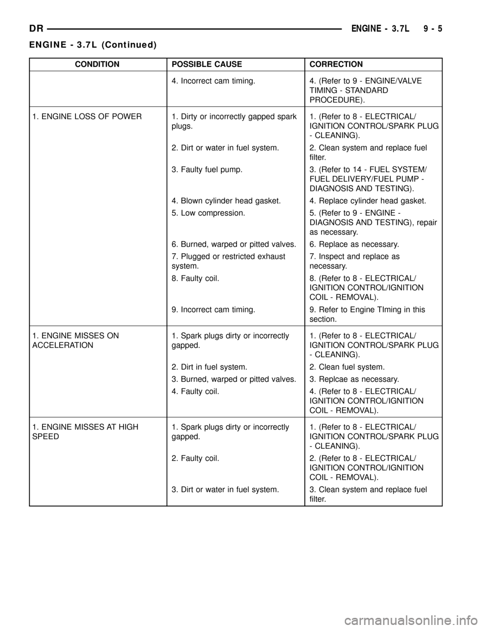
CONDITION POSSIBLE CAUSE CORRECTION
4. Incorrect cam timing. 4. (Refer to 9 - ENGINE/VALVE
TIMING - STANDARD
PROCEDURE).
1. ENGINE LOSS OF POWER 1. Dirty or incorrectly gapped spark
plugs.1. (Refer to 8 - ELECTRICAL/
IGNITION CONTROL/SPARK PLUG
- CLEANING).
2. Dirt or water in fuel system. 2. Clean system and replace fuel
filter.
3. Faulty fuel pump. 3. (Refer to 14 - FUEL SYSTEM/
FUEL DELIVERY/FUEL PUMP -
DIAGNOSIS AND TESTING).
4. Blown cylinder head gasket. 4. Replace cylinder head gasket.
5. Low compression. 5. (Refer to 9 - ENGINE -
DIAGNOSIS AND TESTING), repair
as necessary.
6. Burned, warped or pitted valves. 6. Replace as necessary.
7. Plugged or restricted exhaust
system.7. Inspect and replace as
necessary.
8. Faulty coil. 8. (Refer to 8 - ELECTRICAL/
IGNITION CONTROL/IGNITION
COIL - REMOVAL).
9. Incorrect cam timing. 9. Refer to Engine TIming in this
section.
1. ENGINE MISSES ON
ACCELERATION1. Spark plugs dirty or incorrectly
gapped.1. (Refer to 8 - ELECTRICAL/
IGNITION CONTROL/SPARK PLUG
- CLEANING).
2. Dirt in fuel system. 2. Clean fuel system.
3. Burned, warped or pitted valves. 3. Replcae as necessary.
4. Faulty coil. 4. (Refer to 8 - ELECTRICAL/
IGNITION CONTROL/IGNITION
COIL - REMOVAL).
1. ENGINE MISSES AT HIGH
SPEED1. Spark plugs dirty or incorrectly
gapped.1. (Refer to 8 - ELECTRICAL/
IGNITION CONTROL/SPARK PLUG
- CLEANING).
2. Faulty coil. 2. (Refer to 8 - ELECTRICAL/
IGNITION CONTROL/IGNITION
COIL - REMOVAL).
3. Dirt or water in fuel system. 3. Clean system and replace fuel
filter.
DRENGINE - 3.7L 9 - 5
ENGINE - 3.7L (Continued)
Page 1229 of 2627

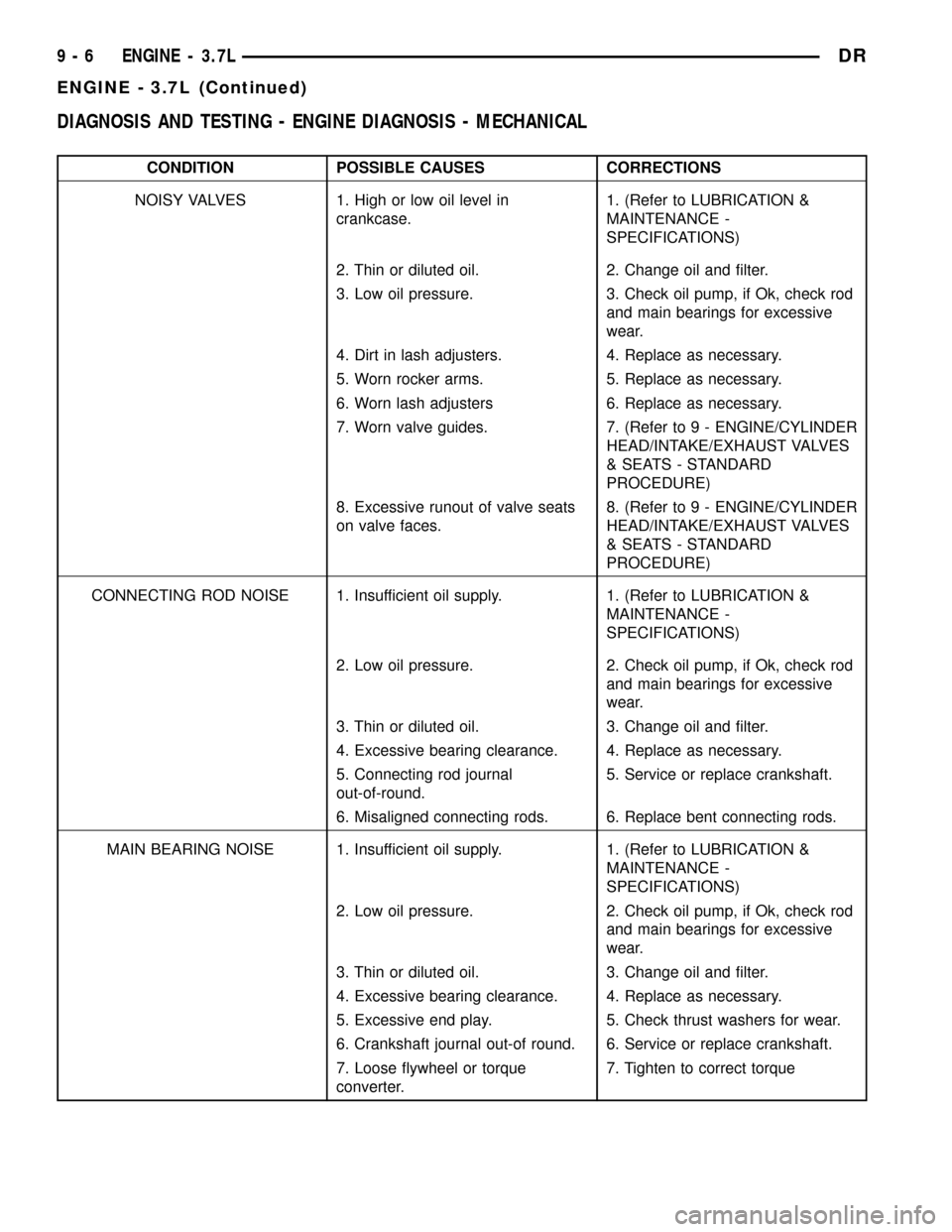
DIAGNOSIS AND TESTING - ENGINE DIAGNOSIS - MECHANICAL
CONDITION POSSIBLE CAUSES CORRECTIONS
NOISY VALVES 1. High or low oil level in
crankcase.1. (Refer to LUBRICATION &
MAINTENANCE -
SPECIFICATIONS)
2. Thin or diluted oil. 2. Change oil and filter.
3. Low oil pressure. 3. Check oil pump, if Ok, check rod
and main bearings for excessive
wear.
4. Dirt in lash adjusters. 4. Replace as necessary.
5. Worn rocker arms. 5. Replace as necessary.
6. Worn lash adjusters 6. Replace as necessary.
7. Worn valve guides. 7. (Refer to 9 - ENGINE/CYLINDER
HEAD/INTAKE/EXHAUST VALVES
& SEATS - STANDARD
PROCEDURE)
8. Excessive runout of valve seats
on valve faces.8. (Refer to 9 - ENGINE/CYLINDER
HEAD/INTAKE/EXHAUST VALVES
& SEATS - STANDARD
PROCEDURE)
CONNECTING ROD NOISE 1. Insufficient oil supply. 1. (Refer to LUBRICATION &
MAINTENANCE -
SPECIFICATIONS)
2. Low oil pressure. 2. Check oil pump, if Ok, check rod
and main bearings for excessive
wear.
3. Thin or diluted oil. 3. Change oil and filter.
4. Excessive bearing clearance. 4. Replace as necessary.
5. Connecting rod journal
out-of-round.5. Service or replace crankshaft.
6. Misaligned connecting rods. 6. Replace bent connecting rods.
MAIN BEARING NOISE 1. Insufficient oil supply. 1. (Refer to LUBRICATION &
MAINTENANCE -
SPECIFICATIONS)
2. Low oil pressure. 2. Check oil pump, if Ok, check rod
and main bearings for excessive
wear.
3. Thin or diluted oil. 3. Change oil and filter.
4. Excessive bearing clearance. 4. Replace as necessary.
5. Excessive end play. 5. Check thrust washers for wear.
6. Crankshaft journal out-of round. 6. Service or replace crankshaft.
7. Loose flywheel or torque
converter.7. Tighten to correct torque
9 - 6 ENGINE - 3.7LDR
ENGINE - 3.7L (Continued)
Page 1231 of 2627

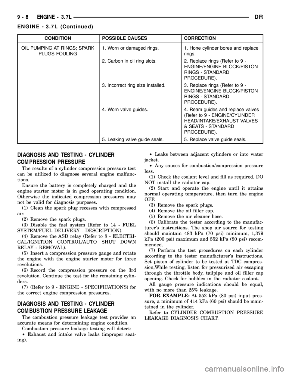
CONDITION POSSIBLE CAUSES CORRECTION
OIL PUMPING AT RINGS; SPARK
PLUGS FOULING1. Worn or damaged rings. 1. Hone cylinder bores and replace
rings.
2. Carbon in oil ring slots. 2. Replace rings (Refer to 9 -
ENGINE/ENGINE BLOCK/PISTON
RINGS - STANDARD
PROCEDURE).
3. Incorrect ring size installed. 3. Replace rings (Refer to 9 -
ENGINE/ENGINE BLOCK/PISTON
RINGS - STANDARD
PROCEDURE).
4. Worn valve guides. 4. Ream guides and replace valves
(Refer to 9 - ENGINE/CYLINDER
HEAD/INTAKE/EXHAUST VALVES
& SEATS - STANDARD
PROCEDURE).
5. Leaking valve guide seals. 5. Replace valve guide seals.
DIAGNOSIS AND TESTING - CYLINDER
COMPRESSION PRESSURE
The results of a cylinder compression pressure test
can be utilized to diagnose several engine malfunc-
tions.
Ensure the battery is completely charged and the
engine starter motor is in good operating condition.
Otherwise the indicated compression pressures may
not be valid for diagnosis purposes.
(1) Clean the spark plug recesses with compressed
air.
(2) Remove the spark plugs.
(3) Disable the fuel system (Refer to 14 - FUEL
SYSTEM/FUEL DELIVERY - DESCRIPTION).
(4) Remove the ASD relay (Refer to 8 - ELECTRI-
CAL/IGNITION CONTROL/AUTO SHUT DOWN
RELAY - REMOVAL).
(5) Insert a compression pressure gauge and rotate
the engine with the engine starter motor for three
revolutions.
(6) Record the compression pressure on the 3rd
revolution. Continue the test for the remaining cylin-
ders.
(7) (Refer to 9 - ENGINE - SPECIFICATIONS) for
the correct engine compression pressures.
DIAGNOSIS AND TESTING - CYLINDER
COMBUSTION PRESSURE LEAKAGE
The combustion pressure leakage test provides an
accurate means for determining engine condition.
Combustion pressure leakage testing will detect:
²Exhaust and intake valve leaks (improper seat-
ing).²Leaks between adjacent cylinders or into water
jacket.
²Any causes for combustion/compression pressure
loss.
(1) Check the coolant level and fill as required. DO
NOT install the radiator cap.
(2) Start and operate the engine until it attains
normal operating temperature, then turn the engine
OFF.
(3) Remove the spark plugs.
(4) Remove the oil filler cap.
(5) Remove the air cleaner hose.
(6) Calibrate the tester according to the manufac-
turer's instructions. The shop air source for testing
should maintain 483 kPa (70 psi) minimum, 1,379
kPa (200 psi) maximum and 552 kPa (80 psi) recom-
mended.
(7) Perform the test procedures on each cylinder
according to the tester manufacturer's instructions.
Set piston of cylinder to be tested at TDC compres-
sion,While testing, listen for pressurized air escaping
through the throttle body, tailpipe and oil filler cap
opening. Check for bubbles in the radiator coolant.
All gauge pressure indications should be equal,
with no more than 25% leakage.
FOR EXAMPLE:At 552 kPa (80 psi) input pres-
sure, a minimum of 414 kPa (60 psi) should be main-
tained in the cylinder.
Refer to CYLINDER COMBUSTION PRESSURE
LEAKAGE DIAGNOSIS CHART.
9 - 8 ENGINE - 3.7LDR
ENGINE - 3.7L (Continued)