1998 DODGE RAM 1500 Cylinder
[x] Cancel search: CylinderPage 1583 of 2627
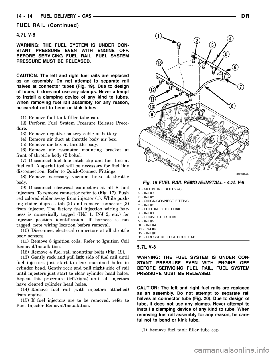
4.7L V-8
WARNING: THE FUEL SYSTEM IS UNDER CON-
STANT PRESSURE EVEN WITH ENGINE OFF.
BEFORE SERVICING FUEL RAIL, FUEL SYSTEM
PRESSURE MUST BE RELEASED.
CAUTION: The left and right fuel rails are replaced
as an assembly. Do not attempt to separate rail
halves at connector tubes (Fig. 19). Due to design
of tubes, it does not use any clamps. Never attempt
to install a clamping device of any kind to tubes.
When removing fuel rail assembly for any reason,
be careful not to bend or kink tubes.
(1) Remove fuel tank filler tube cap.
(2) Perform Fuel System Pressure Release Proce-
dure.
(3) Remove negative battery cable at battery.
(4) Remove air duct at throttle body air box.
(5) Remove air box at throttle body.
(6) Remove air resonator mounting bracket at
front of throttle body (2 bolts).
(7) Disconnect fuel line latch clip and fuel line at
fuel rail. A special tool will be necessary for fuel line
disconnection. Refer to Quick-Connect Fittings.
(8) Remove necessary vacuum lines at throttle
body.
(9) Disconnect electrical connectors at all 8 fuel
injectors. To remove connector refer to (Fig. 17). Push
red colored slider away from injector (1). While push-
ing slider, depress tab (2) and remove connector (3)
from injector. The factory fuel injection wiring har-
ness is numerically tagged (INJ 1, INJ 2, etc.) for
injector position identification. If harness is not
tagged, note wiring location before removal.
(10) Disconnect electrical connectors at all throttle
body sensors.
(11) Remove 8 ignition coils. Refer to Ignition Coil
Removal/Installation.
(12) Remove 4 fuel rail mounting bolts (Fig. 19).
(13) Gently rock and pullleftside of fuel rail until
fuel injectors just start to clear machined holes in
cylinder head. Gently rock and pullrightside of rail
until injectors just start to clear cylinder head holes.
Repeat this procedure (left/right) until all injectors
have cleared cylinder head holes.
(14) Remove fuel rail (with injectors attached)
from engine.
(15) If fuel injectors are to be removed, refer to
Fuel Injector Removal/Installation.
5.7L V-8
WARNING: THE FUEL SYSTEM IS UNDER CON-
STANT PRESSURE EVEN WITH ENGINE OFF.
BEFORE SERVICING FUEL RAIL, FUEL SYSTEM
PRESSURE MUST BE RELEASED.
CAUTION: The left and right fuel rails are replaced
as an assembly. Do not attempt to separate rail
halves at connector tube (Fig. 20). Due to design of
tube, it does not use any clamps. Never attempt to
install a clamping device of any kind to tube. When
removing fuel rail assembly for any reason, be care-
ful not to bend or kink tube.
(1) Remove fuel tank filler tube cap.
Fig. 19 FUEL RAIL REMOVE/INSTALL - 4.7L V-8
1 - MOUNTING BOLTS (4)
2 - INJ.#7
3 - INJ.#5
4 - QUICK-CONNECT FITTING
5 - INJ.#3
6 - FUEL INJECTOR RAIL
7 - INJ.#1
8 - CONNECTOR TUBE
9 - INJ.#2
10 - INJ.#4
11 - INJ.#6
12 - INJ.#8
13 - PRESSURE TEST PORT CAP
14 - 14 FUEL DELIVERY - GASDR
FUEL RAIL (Continued)
Page 1584 of 2627
(2) Perform Fuel System Pressure Release Proce-
dure.
(3) Remove negative battery cable at battery.
(4) Remove flex tube (air cleaner housing to
engine).
(5) Remove air resonator box at throttle body.
(6) Disconnect all spark plug cables from all spark
plugs and ignition coils. Do not remove cables from
cable routing tray. Note original cable positions while
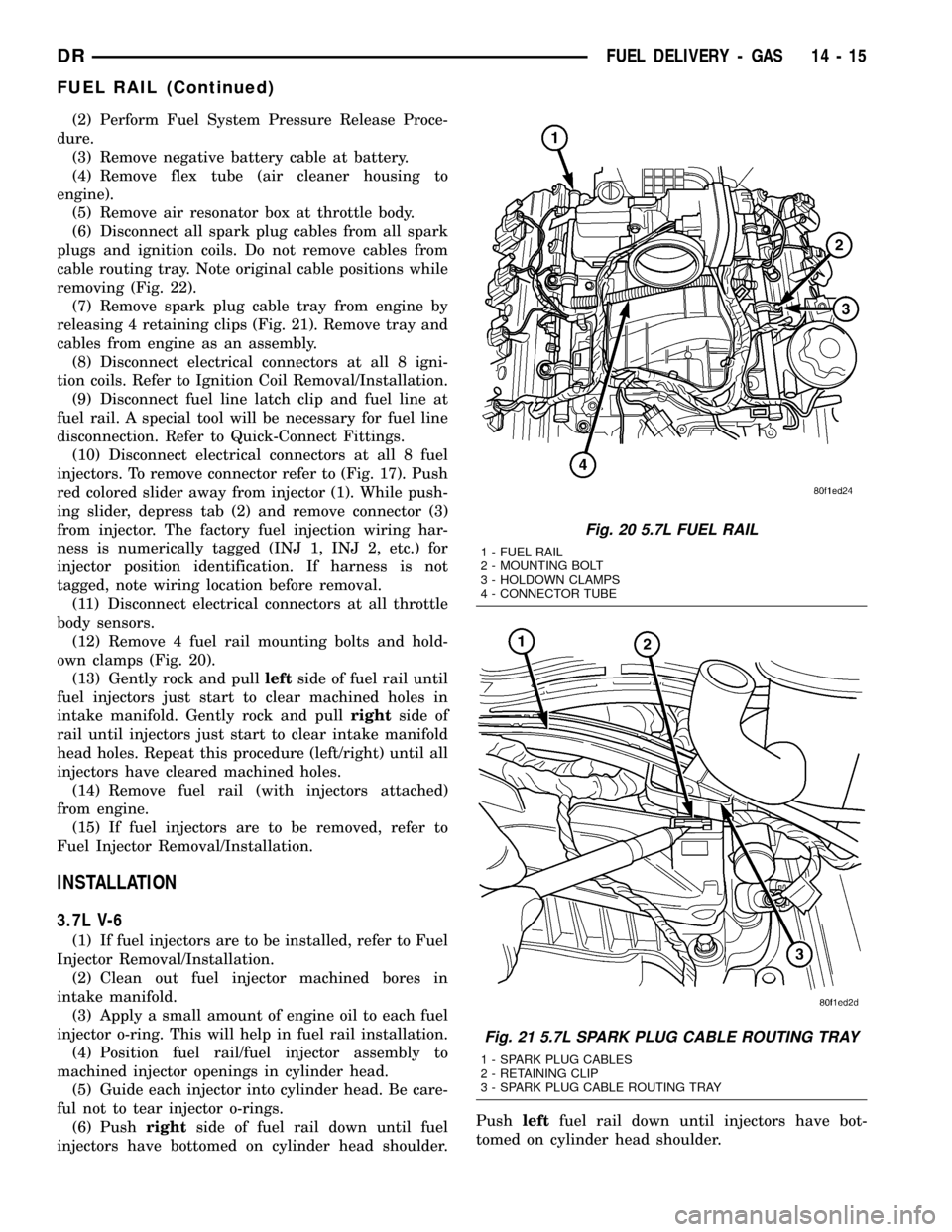
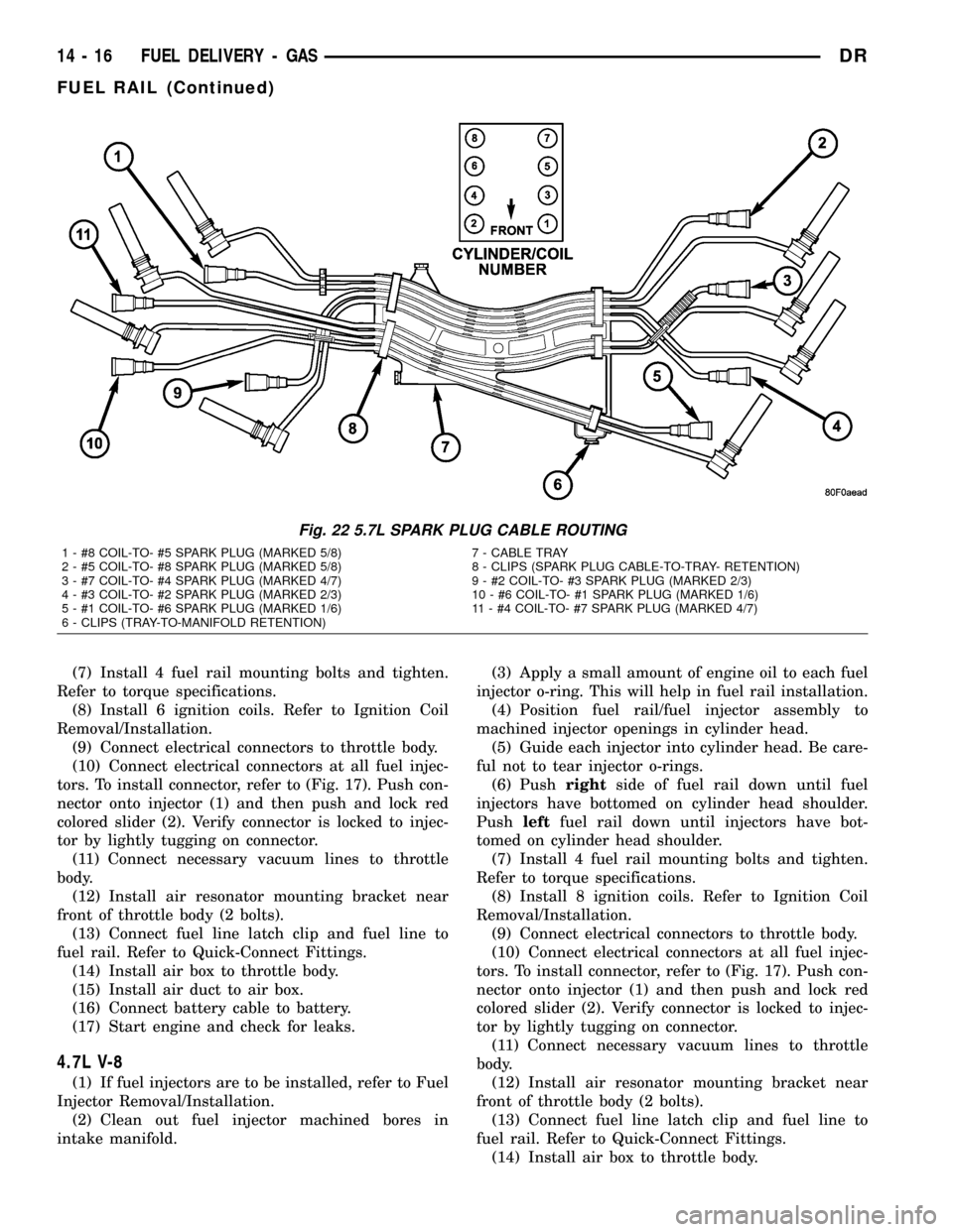
removing (Fig. 22).
(7) Remove spark plug cable tray from engine by
releasing 4 retaining clips (Fig. 21). Remove tray and
cables from engine as an assembly.
(8) Disconnect electrical connectors at all 8 igni-
tion coils. Refer to Ignition Coil Removal/Installation.
(9) Disconnect fuel line latch clip and fuel line at
fuel rail. A special tool will be necessary for fuel line
disconnection. Refer to Quick-Connect Fittings.
(10) Disconnect electrical connectors at all 8 fuel
injectors. To remove connector refer to (Fig. 17). Push
red colored slider away from injector (1). While push-
ing slider, depress tab (2) and remove connector (3)
from injector. The factory fuel injection wiring har-
ness is numerically tagged (INJ 1, INJ 2, etc.) for
injector position identification. If harness is not
tagged, note wiring location before removal.
(11) Disconnect electrical connectors at all throttle
body sensors.
(12) Remove 4 fuel rail mounting bolts and hold-
own clamps (Fig. 20).
(13) Gently rock and pullleftside of fuel rail until
fuel injectors just start to clear machined holes in
intake manifold. Gently rock and pullrightside of
rail until injectors just start to clear intake manifold
head holes. Repeat this procedure (left/right) until all
injectors have cleared machined holes.
(14) Remove fuel rail (with injectors attached)
from engine.
(15) If fuel injectors are to be removed, refer to
Fuel Injector Removal/Installation.
INSTALLATION
3.7L V-6
(1) If fuel injectors are to be installed, refer to Fuel
Injector Removal/Installation.
(2) Clean out fuel injector machined bores in
intake manifold.
(3) Apply a small amount of engine oil to each fuel
injector o-ring. This will help in fuel rail installation.
(4) Position fuel rail/fuel injector assembly to
machined injector openings in cylinder head.
(5) Guide each injector into cylinder head. Be care-
ful not to tear injector o-rings.
(6) Pushrightside of fuel rail down until fuel
injectors have bottomed on cylinder head shoulder.Pushleftfuel rail down until injectors have bot-
tomed on cylinder head shoulder.
Fig. 20 5.7L FUEL RAIL
1 - FUEL RAIL
2 - MOUNTING BOLT
3 - HOLDOWN CLAMPS
4 - CONNECTOR TUBE
Fig. 21 5.7L SPARK PLUG CABLE ROUTING TRAY
1 - SPARK PLUG CABLES
2 - RETAINING CLIP
3 - SPARK PLUG CABLE ROUTING TRAY
DRFUEL DELIVERY - GAS 14 - 15
FUEL RAIL (Continued)
Page 1585 of 2627
(7) Install 4 fuel rail mounting bolts and tighten.
Refer to torque specifications.
(8) Install 6 ignition coils. Refer to Ignition Coil
Removal/Installation.
(9) Connect electrical connectors to throttle body.
(10) Connect electrical connectors at all fuel injec-
tors. To install connector, refer to (Fig. 17). Push con-
nector onto injector (1) and then push and lock red
colored slider (2). Verify connector is locked to injec-
tor by lightly tugging on connector.
(11) Connect necessary vacuum lines to throttle
body.
(12) Install air resonator mounting bracket near
front of throttle body (2 bolts).
(13) Connect fuel line latch clip and fuel line to
fuel rail. Refer to Quick-Connect Fittings.
(14) Install air box to throttle body.
(15) Install air duct to air box.
(16) Connect battery cable to battery.
(17) Start engine and check for leaks.
4.7L V-8
(1) If fuel injectors are to be installed, refer to Fuel
Injector Removal/Installation.
(2) Clean out fuel injector machined bores in
intake manifold.(3) Apply a small amount of engine oil to each fuel
injector o-ring. This will help in fuel rail installation.
(4) Position fuel rail/fuel injector assembly to
machined injector openings in cylinder head.
(5) Guide each injector into cylinder head. Be care-
ful not to tear injector o-rings.
(6) Pushrightside of fuel rail down until fuel
injectors have bottomed on cylinder head shoulder.
Pushleftfuel rail down until injectors have bot-
tomed on cylinder head shoulder.
(7) Install 4 fuel rail mounting bolts and tighten.
Refer to torque specifications.
(8) Install 8 ignition coils. Refer to Ignition Coil
Removal/Installation.
(9) Connect electrical connectors to throttle body.
(10) Connect electrical connectors at all fuel injec-
tors. To install connector, refer to (Fig. 17). Push con-
nector onto injector (1) and then push and lock red
colored slider (2). Verify connector is locked to injec-
tor by lightly tugging on connector.
(11) Connect necessary vacuum lines to throttle
body.
(12) Install air resonator mounting bracket near
front of throttle body (2 bolts).
(13) Connect fuel line latch clip and fuel line to
fuel rail. Refer to Quick-Connect Fittings.
(14) Install air box to throttle body.
Fig. 22 5.7L SPARK PLUG CABLE ROUTING
1 - #8 COIL-TO- #5 SPARK PLUG (MARKED 5/8) 7 - CABLE TRAY
2 - #5 COIL-TO- #8 SPARK PLUG (MARKED 5/8) 8 - CLIPS (SPARK PLUG CABLE-TO-TRAY- RETENTION)
3 - #7 COIL-TO- #4 SPARK PLUG (MARKED 4/7) 9 - #2 COIL-TO- #3 SPARK PLUG (MARKED 2/3)
4 - #3 COIL-TO- #2 SPARK PLUG (MARKED 2/3) 10 - #6 COIL-TO- #1 SPARK PLUG (MARKED 1/6)
5 - #1 COIL-TO- #6 SPARK PLUG (MARKED 1/6) 11 - #4 COIL-TO- #7 SPARK PLUG (MARKED 4/7)
6 - CLIPS (TRAY-TO-MANIFOLD RETENTION)
14 - 16 FUEL DELIVERY - GASDR
FUEL RAIL (Continued)
Page 1592 of 2627
(5) Position APPS assembly to bottom of battery
tray and install 3 bolts. Refer to Torque Specifica-
tions.
(6) Install wheelhouse liner. Refer to Body.
(7)The 5.7L V-8 engine is equipped with a
fully electronic accelerator pedal position sen-
sor. If equipped with a 5.7L, also perform the
following 3 steps:
(a) Connect negative battery cable to battery.
(b) Turn ignition switch ON, but do not crank
engine.
(c) Leave ignition switch ON for a minimum of
10 seconds. This will allow PCM to learn electrical
parameters.
(d) The DRB IIItScan Tool may also be used to
learn electrical parameters. Go to the Miscella-
neous menu, and then select ETC Learn.
(8) If the previous step is not performed, a Diag-
nostic Trouble Code (DTC) will be set.
(9) If necessary, use DRB IIItScan Tool to erase
any Diagnostic Trouble Codes (DTC's) from PCM.
CRANKSHAFT POSITION
SENSOR
DESCRIPTION
3.7L V-6
The Crankshaft Position (CKP) sensor is mounted
into the right rear side of the cylinder block. It is
positioned and bolted into a machined hole.
4.7L V-8
The Crankshaft Position (CKP) sensor is mounted
into the right rear side of the cylinder block. It is
positioned and bolted into a machined hole.
5.7L V-8
The Crankshaft Position (CKP) sensor is mounted
into the right rear side of the cylinder block. It is
positioned and bolted into a machined hole.
OPERATION
3.7L V-6
Engine speed and crankshaft position are provided
through the CKP (Crankshaft Position) sensor. The
sensor generates pulses that are the input sent to the
Powertrain Control Module (PCM). The PCM inter-
prets the sensor input to determine the crankshaft
position. The PCM then uses this position, along with
other inputs, to determine injector sequence and igni-
tion timing.
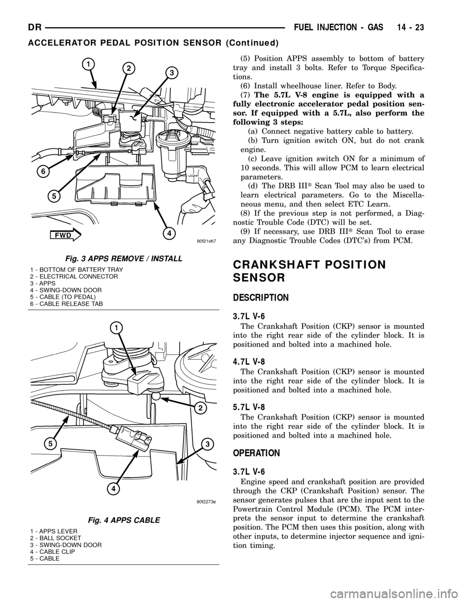
Fig. 3 APPS REMOVE / INSTALL
1 - BOTTOM OF BATTERY TRAY
2 - ELECTRICAL CONNECTOR
3 - APPS
4 - SWING-DOWN DOOR
5 - CABLE (TO PEDAL)
6 - CABLE RELEASE TAB
Fig. 4 APPS CABLE
1 - APPS LEVER
2 - BALL SOCKET
3 - SWING-DOWN DOOR
4 - CABLE CLIP
5 - CABLE
DRFUEL INJECTION - GAS 14 - 23
ACCELERATOR PEDAL POSITION SENSOR (Continued)
Page 1593 of 2627
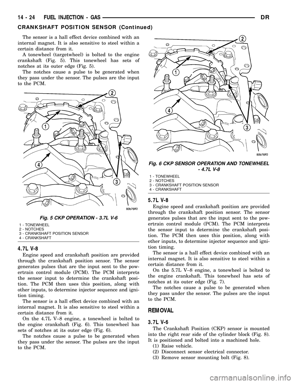
The sensor is a hall effect device combined with an
internal magnet. It is also sensitive to steel within a
certain distance from it.
A tonewheel (targetwheel) is bolted to the engine
crankshaft (Fig. 5). This tonewheel has sets of
notches at its outer edge (Fig. 5).
The notches cause a pulse to be generated when
they pass under the sensor. The pulses are the input
to the PCM.
4.7L V-8
Engine speed and crankshaft position are provided
through the crankshaft position sensor. The sensor
generates pulses that are the input sent to the pow-
ertrain control module (PCM). The PCM interprets
the sensor input to determine the crankshaft posi-
tion. The PCM then uses this position, along with
other inputs, to determine injector sequence and igni-
tion timing.
The sensor is a hall effect device combined with an
internal magnet. It is also sensitive to steel within a
certain distance from it.
On the 4.7L V±8 engine, a tonewheel is bolted to
the engine crankshaft (Fig. 6). This tonewheel has
sets of notches at its outer edge (Fig. 6).
The notches cause a pulse to be generated when
they pass under the sensor. The pulses are the input
to the PCM.
5.7L V-8
Engine speed and crankshaft position are provided
through the crankshaft position sensor. The sensor
generates pulses that are the input sent to the pow-
ertrain control module (PCM). The PCM interprets
the sensor input to determine the crankshaft posi-
tion. The PCM then uses this position, along with
other inputs, to determine injector sequence and igni-
tion timing.
The sensor is a hall effect device combined with an
internal magnet. It is also sensitive to steel within a
certain distance from it.
On the 5.7L V±8 engine, a tonewheel is bolted to
the engine crankshaft. This tonewheel has sets of
notches at its outer edge (Fig. 7).
The notches cause a pulse to be generated when
they pass under the sensor. The pulses are the input
to the PCM.
REMOVAL
3.7L V-6
The Crankshaft Position (CKP) sensor is mounted
into the right rear side of the cylinder block (Fig. 8).
It is positioned and bolted into a machined hole.
(1) Raise vehicle.
(2) Disconnect sensor electrical connector.
(3) Remove sensor mounting bolt (Fig. 8).
Fig. 5 CKP OPERATION - 3.7L V-6
1 - TONEWHEEL
2 - NOTCHES
3 - CRANKSHAFT POSITION SENSOR
4 - CRANKSHAFT
Fig. 6 CKP SENSOR OPERATION AND TONEWHEEL
- 4.7L V-8
1 - TONEWHEEL
2 - NOTCHES
3 - CRANKSHAFT POSITION SENSOR
4 - CRANKSHAFT
14 - 24 FUEL INJECTION - GASDR
CRANKSHAFT POSITION SENSOR (Continued)
Page 1594 of 2627
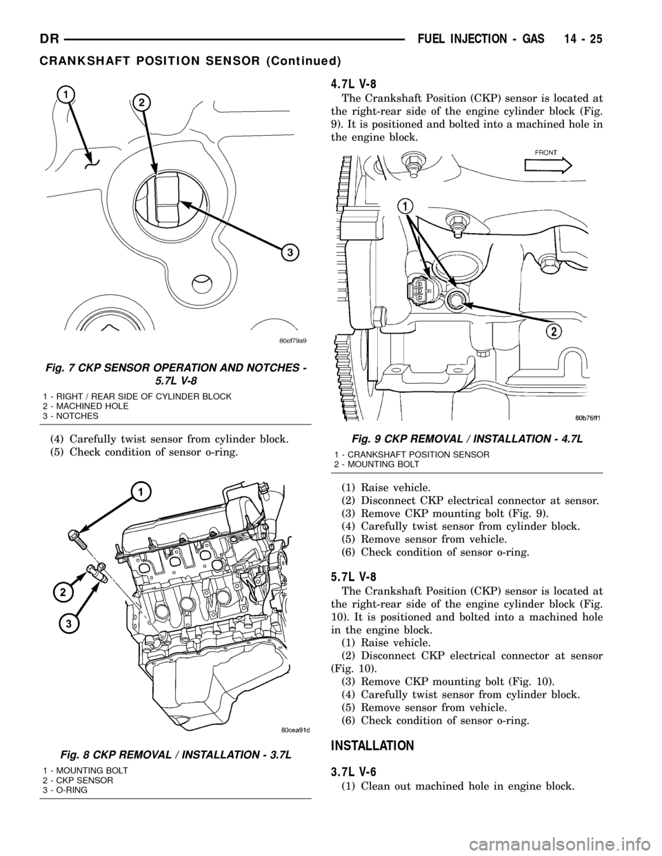
(4) Carefully twist sensor from cylinder block.
(5) Check condition of sensor o-ring.
4.7L V-8
The Crankshaft Position (CKP) sensor is located at
the right-rear side of the engine cylinder block (Fig.
9). It is positioned and bolted into a machined hole in
the engine block.
(1) Raise vehicle.
(2) Disconnect CKP electrical connector at sensor.
(3) Remove CKP mounting bolt (Fig. 9).
(4) Carefully twist sensor from cylinder block.
(5) Remove sensor from vehicle.
(6) Check condition of sensor o-ring.
5.7L V-8
The Crankshaft Position (CKP) sensor is located at
the right-rear side of the engine cylinder block (Fig.
10). It is positioned and bolted into a machined hole
in the engine block.
(1) Raise vehicle.
(2) Disconnect CKP electrical connector at sensor
(Fig. 10).
(3) Remove CKP mounting bolt (Fig. 10).
(4) Carefully twist sensor from cylinder block.
(5) Remove sensor from vehicle.
(6) Check condition of sensor o-ring.
INSTALLATION
3.7L V-6
(1) Clean out machined hole in engine block.
Fig. 7 CKP SENSOR OPERATION AND NOTCHES -
5.7L V-8
1 - RIGHT / REAR SIDE OF CYLINDER BLOCK
2 - MACHINED HOLE
3 - NOTCHES
Fig. 8 CKP REMOVAL / INSTALLATION - 3.7L
1 - MOUNTING BOLT
2 - CKP SENSOR
3 - O-RING
Fig. 9 CKP REMOVAL / INSTALLATION - 4.7L
1 - CRANKSHAFT POSITION SENSOR
2 - MOUNTING BOLT
DRFUEL INJECTION - GAS 14 - 25
CRANKSHAFT POSITION SENSOR (Continued)
Page 1595 of 2627
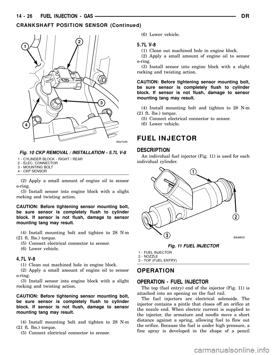
(2) Apply a small amount of engine oil to sensor
o-ring.
(3) Install sensor into engine block with a slight
rocking and twisting action.
CAUTION: Before tightening sensor mounting bolt,
be sure sensor is completely flush to cylinder
block. If sensor is not flush, damage to sensor
mounting tang may result.
(4) Install mounting bolt and tighten to 28 N´m
(21 ft. lbs.) torque.
(5) Connect electrical connector to sensor.
(6) Lower vehicle.
4.7L V-8
(1) Clean out machined hole in engine block.
(2) Apply a small amount of engine oil to sensor
o-ring.
(3) Install sensor into engine block with a slight
rocking and twisting action.
CAUTION: Before tightening sensor mounting bolt,
be sure sensor is completely flush to cylinder
block. If sensor is not flush, damage to sensor
mounting tang may result.
(4) Install mounting bolt and tighten to 28 N´m
(21 ft. lbs.) torque.
(5) Connect electrical connector to sensor.(6) Lower vehicle.
5.7L V-8
(1) Clean out machined hole in engine block.
(2) Apply a small amount of engine oil to sensor
o-ring.
(3) Install sensor into engine block with a slight
rocking and twisting action.
CAUTION: Before tightening sensor mounting bolt,
be sure sensor is completely flush to cylinder
block. If sensor is not flush, damage to sensor
mounting tang may result.
(4) Install mounting bolt and tighten to 28 N´m
(21 ft. lbs.) torque.
(5) Connect electrical connector to sensor.
(6) Lower vehicle.
FUEL INJECTOR
DESCRIPTION
An individual fuel injector (Fig. 11) is used for each
individual cylinder.
OPERATION
OPERATION - FUEL INJECTOR
The top (fuel entry) end of the injector (Fig. 11) is
attached into an opening on the fuel rail.
The fuel injectors are electrical solenoids. The
injector contains a pintle that closes off an orifice at
the nozzle end. When electric current is supplied to
the injector, the armature and needle move a short
distance against a spring, allowing fuel to flow out
the orifice. Because the fuel is under high pressure, a
fine spray is developed in the shape of a pencil
Fig. 10 CKP REMOVAL / INSTALLATION - 5.7L V-8
1 - CYLINDER BLOCK - RIGHT / REAR
2 - ELEC. CONNECTOR
3 - MOUNTING BOLT
4 - CKP SENSOR
Fig. 11 FUEL INJECTOR
1 - FUEL INJECTOR
2 - NOZZLE
3 - TOP (FUEL ENTRY)
14 - 26 FUEL INJECTION - GASDR
CRANKSHAFT POSITION SENSOR (Continued)
Page 1596 of 2627
stream. The spraying action atomizes the fuel, add-
ing it to the air entering the combustion chamber.
The nozzle (outlet) ends of the injectors are posi-
tioned into openings in the intake manifold just
above the intake valve ports of the cylinder head.
The engine wiring harness connector for each fuel
injector is equipped with an attached numerical tag
(INJ 1, INJ 2 etc.). This is used to identify each fuel
injector.
The injectors are energized individually in a
sequential order by the Powertrain Control Module
(PCM). The PCM will adjust injector pulse width by
switching the ground path to each individual injector
on and off. Injector pulse width is the period of time
that the injector is energized. The PCM will adjust
injector pulse width based on various inputs it
receives.
Battery voltage is supplied to the injectors through
the ASD relay.
The PCM determines injector pulse width based on
various inputs.
OPERATION - PCM OUTPUT
The nozzle ends of the injectors are positioned into
openings in the intake manifold just above the intake
valve ports of the cylinder head. The engine wiring
harness connector for each fuel injector is equipped
with an attached numerical tag (INJ 1, INJ 2 etc.).
This is used to identify each fuel injector with its
respective cylinder number.
The injectors are energized individually in a
sequential order by the Powertrain Control Module
(PCM). The PCM will adjust injector pulse width by
switching the ground path to each individual injector
on and off. Injector pulse width is the period of time
that the injector is energized. The PCM will adjust
injector pulse width based on various inputs it
receives.
Battery voltage (12 volts +) is supplied to the injec-
tors through the ASD relay. The ASD relay will shut-
down the 12 volt power source to the fuel injectors if
the PCM senses the ignition is on, but the engine is
not running. This occurs after the engine has not
been running for approximately 1.8 seconds.
The PCM determines injector on-time (pulse width)
based on various inputs.
REMOVAL
(1) Remove fuel rail. Refer to Fuel Injector Rail
Removal.
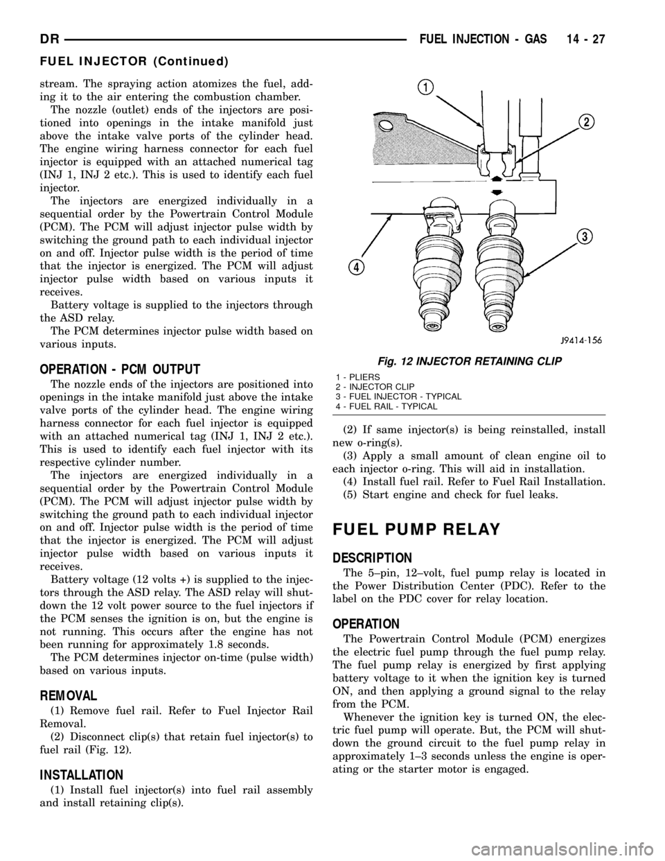
(2) Disconnect clip(s) that retain fuel injector(s) to
fuel rail (Fig. 12).
INSTALLATION
(1) Install fuel injector(s) into fuel rail assembly
and install retaining clip(s).(2) If same injector(s) is being reinstalled, install
new o-ring(s).
(3) Apply a small amount of clean engine oil to
each injector o-ring. This will aid in installation.
(4) Install fuel rail. Refer to Fuel Rail Installation.
(5) Start engine and check for fuel leaks.
FUEL PUMP RELAY
DESCRIPTION
The 5±pin, 12±volt, fuel pump relay is located in
the Power Distribution Center (PDC). Refer to the
label on the PDC cover for relay location.
OPERATION
The Powertrain Control Module (PCM) energizes
the electric fuel pump through the fuel pump relay.
The fuel pump relay is energized by first applying
battery voltage to it when the ignition key is turned
ON, and then applying a ground signal to the relay
from the PCM.
Whenever the ignition key is turned ON, the elec-
tric fuel pump will operate. But, the PCM will shut-
down the ground circuit to the fuel pump relay in
approximately 1±3 seconds unless the engine is oper-
ating or the starter motor is engaged.
Fig. 12 INJECTOR RETAINING CLIP
1 - PLIERS
2 - INJECTOR CLIP
3 - FUEL INJECTOR - TYPICAL
4 - FUEL RAIL - TYPICAL
DRFUEL INJECTION - GAS 14 - 27
FUEL INJECTOR (Continued)