1998 DODGE RAM 1500 Cylinder
[x] Cancel search: CylinderPage 1505 of 2627
NOTE: If cylinders have ridges, the cylinders are
oversize and will more than likely need boring.
(8) Using a hammer and steel stamp, stamp the
cylinder number in the top of each piston. The front
of the piston is identified by a stamping on the top of
the piston. DO NOT stamp in the outside 5 mm (.197
in.) of the piston diameter. DO NOT stamp over the
piston pin.
(9) Mark the connecting rod and cap with the cor-
responding cylinder numbers.
(10) Remove the connecting rod bolts and rod caps.
Use care so the cylinder bores and connecting rods
are not damaged.
(11) Use a hammer handle or similar object to
push the piston and connecting rod through the cyl-
inder bore.
(12) Store the piston/rod assemblies in a rack.
CLEANINGÐPISTON AND CONNECTING ROD
CAUTION: DO NOT use bead blast to clean the pis-
tons. DO NOT clean the pistons and rods in an acid
tank.
PISTON
Clean the pistons and pins in a suitable solvent,
rinse in hot water and blow dry with compressed air.
Soaking the pistons over night will loosen most of the
carbon build up. De-carbon the ring grooves with a
broken piston ring and again clean the pistons in sol-
vent. Rinse in hot water and blow dry with com-
pressed air.
CONNECTING ROD
Clean the connecting rods in a suitable solvent,
rinse in hot water and blow dry with compressed air.
INSPECTION
INSPECTION - PISTONS
Inspect the pistons for damage and excessive wear.
Check top of the piston, ring grooves, skirt and pin
bore. Measure the piston skirt diameter. If the piston
is out of limits, replace the piston.
PISTON SKIRT DIAMETER (MIN.)
101.775 mm (4.006 in. )The upper groove only needs to be inspected for
damage. Use a new piston ring to measure the clear-
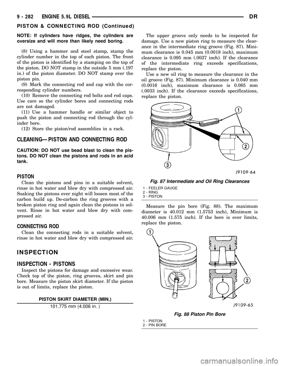
ance in the intermediate ring groove (Fig. 87). Mini-
mum clearance is 0.045 mm (0.0018 inch), maximum
clearance is 0.095 mm (.0037 inch). If the clearance
of the intermediate ring exceeds specifications,
replace the piston.
Use a new oil ring to measure the clearance in the
oil groove (Fig. 87). Minimum clearance is 0.040 mm
(0.0016 inch), maximum clearance is 0.085 mm
(.0033 inch). If the clearance exceeds specifications,
replace the piston.
Measure the pin bore (Fig. 88). The maximum
diameter is 40.012 mm (1.5753 inch), Minimum is
40.006 mm (1.575 inch). If the bore is over limits,
replace the piston.
Fig. 87 Intermediate and Oil Ring Clearances
1 - FEELER GAUGE
2 - RING
3 - PISTON
Fig. 88 Piston Pin Bore
1 - PISTON
2 - PIN BORE
9 - 282 ENGINE 5.9L DIESELDR
PISTON & CONNECTING ROD (Continued)
Page 1506 of 2627
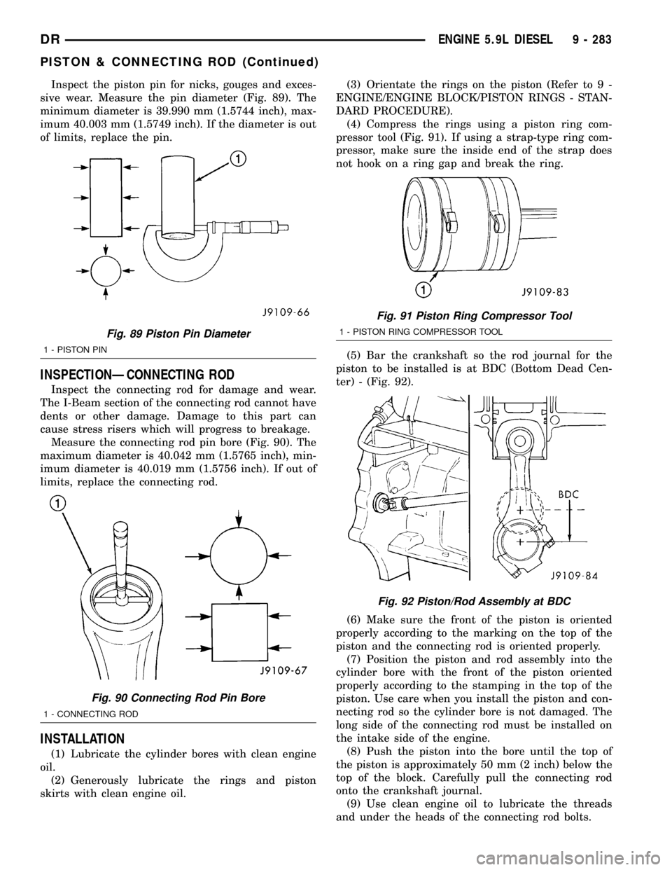
Inspect the piston pin for nicks, gouges and exces-
sive wear. Measure the pin diameter (Fig. 89). The
minimum diameter is 39.990 mm (1.5744 inch), max-
imum 40.003 mm (1.5749 inch). If the diameter is out
of limits, replace the pin.
INSPECTIONÐCONNECTING ROD
Inspect the connecting rod for damage and wear.
The I-Beam section of the connecting rod cannot have
dents or other damage. Damage to this part can
cause stress risers which will progress to breakage.
Measure the connecting rod pin bore (Fig. 90). The
maximum diameter is 40.042 mm (1.5765 inch), min-
imum diameter is 40.019 mm (1.5756 inch). If out of
limits, replace the connecting rod.
INSTALLATION
(1) Lubricate the cylinder bores with clean engine
oil.
(2) Generously lubricate the rings and piston
skirts with clean engine oil.(3) Orientate the rings on the piston (Refer to 9 -
ENGINE/ENGINE BLOCK/PISTON RINGS - STAN-
DARD PROCEDURE).
(4) Compress the rings using a piston ring com-
pressor tool (Fig. 91). If using a strap-type ring com-
pressor, make sure the inside end of the strap does
not hook on a ring gap and break the ring.
(5) Bar the crankshaft so the rod journal for the
piston to be installed is at BDC (Bottom Dead Cen-
ter) - (Fig. 92).
(6) Make sure the front of the piston is oriented
properly according to the marking on the top of the
piston and the connecting rod is oriented properly.
(7) Position the piston and rod assembly into the
cylinder bore with the front of the piston oriented
properly according to the stamping in the top of the
piston. Use care when you install the piston and con-
necting rod so the cylinder bore is not damaged. The
long side of the connecting rod must be installed on
the intake side of the engine.
(8) Push the piston into the bore until the top of
the piston is approximately 50 mm (2 inch) below the
top of the block. Carefully pull the connecting rod
onto the crankshaft journal.
(9) Use clean engine oil to lubricate the threads
and under the heads of the connecting rod bolts.
Fig. 89 Piston Pin Diameter
1 - PISTON PIN
Fig. 90 Connecting Rod Pin Bore
1 - CONNECTING ROD
Fig. 91 Piston Ring Compressor Tool
1 - PISTON RING COMPRESSOR TOOL
Fig. 92 Piston/Rod Assembly at BDC
DRENGINE 5.9L DIESEL 9 - 283
PISTON & CONNECTING ROD (Continued)
Page 1507 of 2627
(10)For fractured/split type connecting rods,
the long end of the rod must be installed towards the
intake side of the engine.
(a) The connecting rod split/face must face
toward the same side as the piston notch feature
on the skirt. The split face will face toward the
exhaust side of the engine if properly installed.
(11) Install the rod cap and bolts to the connecting
rod. Tighten the connecting rod bolts evenly in 3
steps.
²Tighten the bolts to 30 N´m (22 ft. lbs.) torque.
²Tighten the bolts to 60 N´m (44 ft. lbs.) torque.
²Rotate 60É clockwise.
(12) The crankshaft must rotate freely. Check for
freedom of rotation as the caps are installed. If the
crankshaft does not rotate freely, check the installa-
tion of the rod bearing and the bearing size.
(13) Measure the side clearance between the con-
necting rod and the crankshaft. DO NOT measure
the clearance between the cap and crankshaft.
(14) Install J-jet piston cooling nozzles if equipped.
(15) Install block stiffener. Torque to 43 N´m (32 ft.
lbs.).
(16) Install the suction tube and oil pan (Refer to 9
- ENGINE/LUBRICATION/OIL PAN - INSTALLA-
TION).
(17) Install the cylinder head onto the engine
(Refer to 9 - ENGINE/CYLINDER HEAD - INSTAL-
LATION).
(18) Install a new filter and fill the crankcase with
new engine oil.Prefill the filter with clean oil.
(19) Connect the battery negative cables and start
engine.
PISTON RINGS
STANDARD PROCEDURE - PISTON RING
FITTING
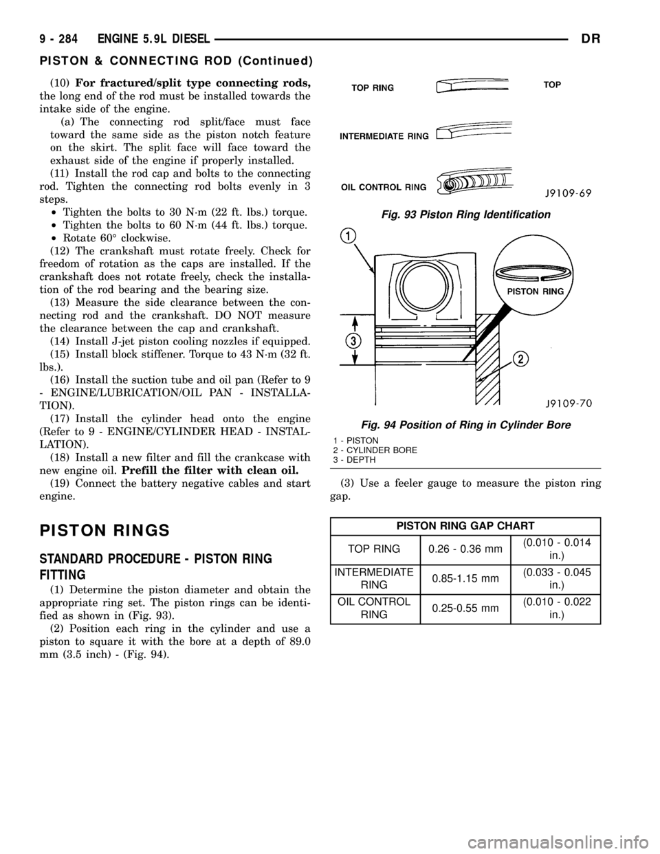
(1) Determine the piston diameter and obtain the
appropriate ring set. The piston rings can be identi-
fied as shown in (Fig. 93).
(2) Position each ring in the cylinder and use a
piston to square it with the bore at a depth of 89.0
mm (3.5 inch) - (Fig. 94).(3) Use a feeler gauge to measure the piston ring
gap.
PISTON RING GAP CHART
TOP RING 0.26 - 0.36 mm(0.010 - 0.014
in.)
INTERMEDIATE
RING0.85-1.15 mm(0.033 - 0.045
in.)
OIL CONTROL
RING0.25-0.55 mm(0.010 - 0.022
in.)
Fig. 93 Piston Ring Identification
Fig. 94 Position of Ring in Cylinder Bore
1 - PISTON
2 - CYLINDER BORE
3 - DEPTH
9 - 284 ENGINE 5.9L DIESELDR
PISTON & CONNECTING ROD (Continued)
Page 1512 of 2627
LUBRICATION
DESCRIPTION
NOTE: Refer to (Fig. 105) and (Fig. 106) for circuit
illustrations.
A gear driven gerotor type oil pump is mounted
behind the front gear cover in the lower right portion
on the engine.
OPERATION
A gerotor style oil pump draws oil from the crank-
case through the suction tube and delivers it through
the block where it enters the oil cooler cover and
pressure regulator valve. When oil pressure exceeds
517 kPa (75 PSI), the valve opens exposing the dump
port, which routes excess oil back to the oil pump.
At the same time, oil is directed to a cast in pas-
sage in the oil cooler cover, leading to the oil cooler
element. As the oil travels through the element
plates, it is cooled by engine coolant traveling past
the outside of the plates. It is then routed to the oil
filter head and through a full flow oil filter. If a
plugged filter is encountered, the filter by-pass valve
opens, allowing unfiltered oil to lubricate the engine.
This condition can be avoided by frequent oil and fil-
ter changes, per the maintenance schedules found in
the owners manual. The by-pass valve is calibrated
to open when it sees a pressure drop of more than
345 kPa (50 psi) across the oil filter.
The oil filter head then divides the oil between the
engine and the turbocharger. The turbocharger
receives filtered, cooled and pressurized oil through a
supply line from the filter head. The oil lubricates
the turbocharger and returns to the pan by way of a
drain tube connecting the bottom of the turbocharger
to a pressed in tube in the cylinder block.
Oil is then carried across the block to an angle
drilling which intersects the main oil rifle. The main
oil rifle runs the length of the block and delivers oil
to the crankshaft main journals and valve train. Oil
travels to the crankshaft through a series of transfer
drillings (one for each main bearing) and lubricates a
groove in the main bearing upper shell. From there
another drilling feeds the camshaft main journals.The saddle jet piston cooling nozzles are also sup-
plied by the main bearing upper shell. J-jet piston
cooling nozzles are supplied by a separate oil rifle.
Plugs are used in place of saddle jets when J-jets are
used. J-jet hole locations are plugged when saddle jet
cooling nozzles are used. Crankshaft internal cross-
drillings supply oil to the connecting rod journals.
Another series of transfer drillings intersecting the
main oil rifle supply the valve train components. Oil
travels up the drilling, through a hole in the head
gasket, and through a drilling in the cylinder head
(one per cylinder), where it enters the rocker arm
pedestal and is divided between the intake and
exhaust rocker arm. Oil travels up and around the
rocker arm mounting bolt, and lubricates the rocker
shaft by cross drillings that intersect the mounting
bolt hole. Grooves at both ends of the rocker shaft
supply oil through the rocker arm where the oil trav-
els to the push rod and socket balls (Fig. 105) and
(Fig. 106).
DIAGNOSIS AND TESTINGÐENGINE OIL
PRESSURE
(1) Remove the 1/8 npt plug from the top of the oil
filter housing.
(2) Install Oil Pressure Line and Gauge Tool
C-3292 with a suitable adapter.
(3) Start engine and warm to operating tempera-
ture.
(4) Record engine oil pressure and compare with
engine oil pressure chart.
CAUTION: If engine oil pressure is zero at idle, DO
NOT RUN THE ENGINE.
Engine Oil Pressure (MIN)
At Idle 68.9 kPa (10 psi)
At 2500 rpm 206.9 kPa (30 psi)
If minimum engine oil pressure is below these
ranges, (Refer to 9 - ENGINE - DIAGNOSIS AND
TESTING).
(5) Remove oil pressure gauge and install the 1/8
npt plug.
DRENGINE 5.9L DIESEL 9 - 289
Page 1516 of 2627
OIL COOLER & LINES
CLEANING
CLEANING AND INSPECTION
Clean the sealing surfaces.
Apply 483 kPa (70 psi) air pressure to the element
to check for leaks. If the element leaks, replace the
element.
OIL FILTER
REMOVAL
(1) Clean the area around the oil filter head.
Remove the filter from below using a cap-style filter
wrench.
(2) Clean the gasket surface of the filter head. The
filter canister O-Ring seal can stick on the filter
head. Make sure it is removed.
INSTALLATION
(1) Fill the oil filter element with clean oil before
installation. Use the same type oil that will be used
in the engine.
(2) Apply a light film of lubricating oil to the seal-
ing surface before installing the filter.
CAUTION: Mechanical over-tightening may distort
the threads or damage the filter element seal.
(3) Install the filter until it contacts the sealing
surface of the oil filter adapter. Tighten filter an
additional
1¤2turn.
OIL PAN
REMOVAL
(1) Disconnect the battery negative cables.
(2) Install engine support fixture # 8534.
(3) Raise vehicle on hoist.
(4) Disconnect starter cables from starter motor.
(5) Remove transmission and transfer case (if
equipped).
(6) Remove flywheel or flexplate.
(7) Remove starter motor (Refer to 8 - ELECTRI-
CAL/STARTING/STARTER MOTOR - REMOVAL)
and transmission adapter plate assembly.
WARNING: HOT OIL CAN CAUSE PERSONAL
INJURY.
(8) Drain the engine oil (Refer to 9 - ENGINE/LU-
BRICATION/OIL - STANDARD PROCEDURE).(9) Install the oil pan drain plug if sealing surface
is not damaged and tighten to 50 N´m (37 ft. lbs.)
torque.
(10) Remove oil pan bolts, break the pan to block
seal, and lower pan slightly and remove oil suction
tube fasteners.
(11) Remove oil pan and suction tube.
CLEANING
Remove all gasket material from the oil pan and
cylinder block sealing surfaces. Extra effort may be
required around T-joint areas. Clean oil pan and
flush suction tube with a suitable solvent.
INSPECTION
Inspect the oil pan, suction tube, and tube braces
for cracks and damage. Replace any defective compo-
nent. Inspect the oil drain plug and drain hole
threads. Inspect the oil pan sealing surface for
straightness. Repair any minor imperfections with a
ball-peen hammer. Do not attempt to repair an oil
pan by welding.
INSTALLATION
(1) Fill the T-joint between the pan rail/gear hous-
ing and pan rail/rear seal retainer with sealant. Use
MopartSilicone Rubber Adhesive Sealant or equiva-
lent.
(2) Place suction tube in oil pan and guide them
into place. Using a new tube to block gasket, install
and tighten the suction tube bolts by hand. Starting
with the oil pump inlet bolts, tighten the bolts to 24
N´m (18 ft. lbs.) torque. Tighten the remaining tube
brace bolts to 43 N´m (32 ft. lbs.) torque.
(3) Starting in the center and working outward,
tighten the oil pan bolts to 28 N´m (21 ft. lbs.)
torque.
(4) Install the flywheel housing assembly with the
starter motor attached and tighten bolts to 77 N´m
(57 ft. lbs.) torque.
(5) Connect starter motor cables.
(6) Install the flywheel or flexplate. Torque to 137
N´m (101 ft. lbs.).
(7) Install transmission and transfer case (if
equipped).
(8) Lower vehicle.
(9) Remove the engine support fixture # 8534.
(10) Install battery negative cables.
(11) Fill the crankcase with new engine oil.
(12) Start engine and check for leaks. Stop engine,
check oil level, and adjust, if necessary.
DRENGINE 5.9L DIESEL 9 - 293
Page 1518 of 2627
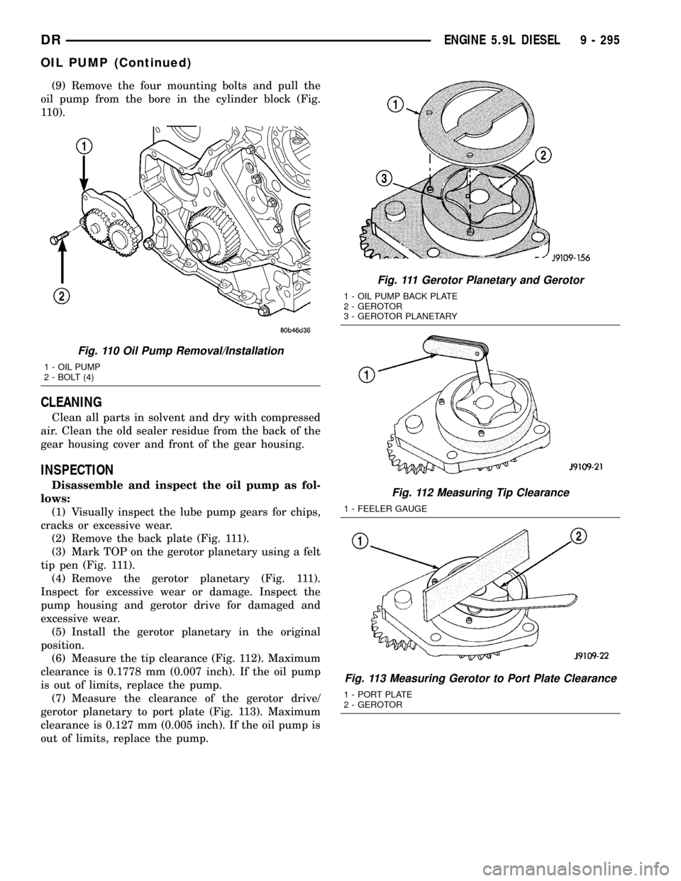
(9) Remove the four mounting bolts and pull the
oil pump from the bore in the cylinder block (Fig.
110).
CLEANING
Clean all parts in solvent and dry with compressed
air. Clean the old sealer residue from the back of the
gear housing cover and front of the gear housing.
INSPECTION
Disassemble and inspect the oil pump as fol-
lows:
(1) Visually inspect the lube pump gears for chips,
cracks or excessive wear.
(2) Remove the back plate (Fig. 111).
(3) Mark TOP on the gerotor planetary using a felt
tip pen (Fig. 111).
(4) Remove the gerotor planetary (Fig. 111).
Inspect for excessive wear or damage. Inspect the
pump housing and gerotor drive for damaged and
excessive wear.
(5) Install the gerotor planetary in the original
position.
(6) Measure the tip clearance (Fig. 112). Maximum
clearance is 0.1778 mm (0.007 inch). If the oil pump
is out of limits, replace the pump.
(7) Measure the clearance of the gerotor drive/
gerotor planetary to port plate (Fig. 113). Maximum
clearance is 0.127 mm (0.005 inch). If the oil pump is
out of limits, replace the pump.
Fig. 110 Oil Pump Removal/Installation
1 - OIL PUMP
2 - BOLT (4)
Fig. 111 Gerotor Planetary and Gerotor
1 - OIL PUMP BACK PLATE
2 - GEROTOR
3 - GEROTOR PLANETARY
Fig. 112 Measuring Tip Clearance
1 - FEELER GAUGE
Fig. 113 Measuring Gerotor to Port Plate Clearance
1 - PORT PLATE
2 - GEROTOR
DRENGINE 5.9L DIESEL 9 - 295
OIL PUMP (Continued)
Page 1519 of 2627
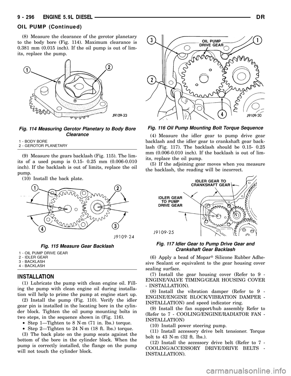
(8) Measure the clearance of the gerotor planetary
to the body bore (Fig. 114). Maximum clearance is
0.381 mm (0.015 inch). If the oil pump is out of lim-
its, replace the pump.
(9) Measure the gears backlash (Fig. 115). The lim-
its of a used pump is 0.15- 0.25 mm (0.006-0.010
inch). If the backlash is out of limits, replace the oil
pump.
(10) Install the back plate.
INSTALLATION
(1) Lubricate the pump with clean engine oil. Fill-
ing the pump with clean engine oil during installa-
tion will help to prime the pump at engine start up.
(2) Install the pump (Fig. 110). Verify the idler
gear pin is installed in the locating bore in the cylin-
der block. Tighten the oil pump mounting bolts in
two steps, in the sequence shown in (Fig. 116).
²Step 1ÐTighten to 8 N´m (71 in. lbs.) torque.
²Step 2ÐTighten to 24 N´m (18 ft. lbs.) torque.
(3) The back plate on the pump seats against the
bottom of the bore in the cylinder block. When the
pump is correctly installed, the flange on the pump
will not touch the cylinder block.(4) Measure the idler gear to pump drive gear
backlash and the idler gear to crankshaft gear back-
lash (Fig. 117). The backlash should be 0.15- 0.25
mm (0.006-0.010 inch). If the backlash is out of lim-
its, replace the oil pump.
(5) If the adjoining gear moves when you measure
the backlash, the reading will be incorrect.
(6) Apply a bead of MopartSilicone Rubber Adhe-
sive Sealant or equivalent to the gear housing cover
sealing surface.
(7) Install the gear housing cover (Refer to 9 -
ENGINE/VALVE TIMING/GEAR HOUSING COVER
- INSTALLATION).
(8) Install the vibration damper (Refer to 9 -
ENGINE/ENGINE BLOCK/VIBRATION DAMPER -
INSTALLATION) and speed indicator ring.
(9) Install the fan support/hub assembly Refer to
(Refer to 7 - COOLING/ENGINE/RADIATOR FAN -
INSTALLATION)
(10) Install power steering pump.
(11) Install accessory drive belt tensioner. Torque
bolt to 43 N´m (32 ft. lbs.).
(12) Install the accessory drive belt (Refer to 7 -
COOLING/ACCESSORY DRIVE/DRIVE BELTS -
INSTALLATION).
Fig. 114 Measuring Gerotor Planetary to Body Bore
Clearance
1 - BODY BORE
2 - GEROTOR PLANETARY
Fig. 115 Measure Gear Backlash
1 - OIL PUMP DRIVE GEAR
2 - IDLER GEAR
3 - BACKLASH
4 - BACKLASH
Fig. 116 Oil Pump Mounting Bolt Torque Sequence
Fig. 117 Idler Gear to Pump Drive Gear and
Crankshaft Gear Backlash
9 - 296 ENGINE 5.9L DIESELDR
OIL PUMP (Continued)
Page 1520 of 2627
(13) Install the cooling fan (Refer to 7 - COOLING/
ENGINE/RADIATOR FAN - INSTALLATION).
(14) Connect battery negative cables.
(15) Start engine and check for oil leaks.
INTAKE MANIFOLD
REMOVAL
(1) Disconnect the battery negative cables.
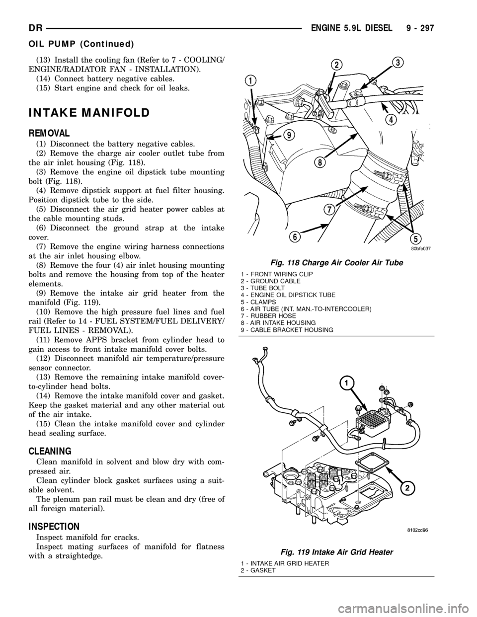
(2) Remove the charge air cooler outlet tube from
the air inlet housing (Fig. 118).
(3) Remove the engine oil dipstick tube mounting
bolt (Fig. 118).
(4) Remove dipstick support at fuel filter housing.
Position dipstick tube to the side.
(5) Disconnect the air grid heater power cables at
the cable mounting studs.
(6) Disconnect the ground strap at the intake
cover.
(7) Remove the engine wiring harness connections
at the air inlet housing elbow.
(8) Remove the four (4) air inlet housing mounting
bolts and remove the housing from top of the heater
elements.
(9) Remove the intake air grid heater from the
manifold (Fig. 119).
(10) Remove the high pressure fuel lines and fuel
rail (Refer to 14 - FUEL SYSTEM/FUEL DELIVERY/
FUEL LINES - REMOVAL).
(11) Remove APPS bracket from cylinder head to
gain access to front intake manifold cover bolts.
(12) Disconnect manifold air temperature/pressure
sensor connector.
(13) Remove the remaining intake manifold cover-
to-cylinder head bolts.
(14) Remove the intake manifold cover and gasket.
Keep the gasket material and any other material out
of the air intake.
(15) Clean the intake manifold cover and cylinder
head sealing surface.
CLEANING
Clean manifold in solvent and blow dry with com-
pressed air.
Clean cylinder block gasket surfaces using a suit-
able solvent.
The plenum pan rail must be clean and dry (free of
all foreign material).
INSPECTION
Inspect manifold for cracks.
Inspect mating surfaces of manifold for flatness
with a straightedge.
Fig. 118 Charge Air Cooler Air Tube
1 - FRONT WIRING CLIP
2 - GROUND CABLE
3 - TUBE BOLT
4 - ENGINE OIL DIPSTICK TUBE
5 - CLAMPS
6 - AIR TUBE (INT. MAN.-TO-INTERCOOLER)
7 - RUBBER HOSE
8 - AIR INTAKE HOUSING
9 - CABLE BRACKET HOUSING
Fig. 119 Intake Air Grid Heater
1 - INTAKE AIR GRID HEATER
2 - GASKET
DRENGINE 5.9L DIESEL 9 - 297
OIL PUMP (Continued)