1998 DODGE RAM 1500 Cylinder
[x] Cancel search: CylinderPage 1490 of 2627
After removing the boring bar, use a honing stone
to chamfer the corner of the repair sleeve(s).
SLEEVE MACHINING DIMENSIONS CHART
ITEM MEASUREMENT
SLEEVE PROTRUSION MIN. - FLUSH WITH
BLOCK
MAX. - 0.050 mm
(0.0019 in.)
SLEEVE DIAMETER 101.956 mm (4.014 in.)
SLEEVE CHAMFER APPROX. 1.25 mm
(0.049 in.) by 15É
A correctly honed surface will have a crosshatch
appearance with the lines at 15É to 25É angles with
the top of the cylinder block. For the rough hone, use
80 grit honing stones. To finish hone, use 280 grit
honing stones.
Finished bore inside dimension is 102.020 0.020
mm (4.0165 0.0008 inch).
A maximum of 1.2 micrometer (48 microinch) sur-
face finish must be obtained.
After finish honing is complete, immediately clean
the cylinder bores with a strong solution of laundry
detergent and hot water.
After rinsing, blow the block dry with compressed
air.
Wipe the bore with a white, lint-free, lightly oiled
cloth. Make sure there is no grit residue present.
Apply a rust-preventing compound if the block will
not be used immediately.
A standard diameter piston and a piston ring set
must be used with a sleeved cylinder bore.
STANDARD PROCEDUREÐCAM BORE REPAIR
For standard bushings, not oversized, maximum
front and rear cam bushing bore diameter is 59.248
mm. (2.3326 in.). DO NOT bore the intermediate cam
bore to the front cam bore oversize dimensions. Max-
imum front and rear camshaft bushing installed
diameter is 54.147 mm. (2.1318 in.). Minimum
installed diameter is 54.083 mm. (2.1293 in.). Maxi-
mum intermediate camshaft bore diameter is 54.164
mm. (2.1324 in.).
A surface finish of 2.3 micrometers (92 microinch)
must be maintained. Not more than 20% of an area
of any one bore may be 3.2 micrometers (126 micro-
inch).
Camshaft bores can be repaired individually. It is
not necessary to repair undamaged cam bores in
order to repair individually damaged cam bores. The
standard front bushing cannot be used to repair
intermediate bores.Install all cam bushings flush or below the front
and rear cam bore surface. The front camshaft bush-
ing should be installed flush with front face of block.
The rear camshaft bushing should be installed flush
with rear face of block. The oil hole must align to
allow a 3.2 mm (0.125 inch) rod to pass through
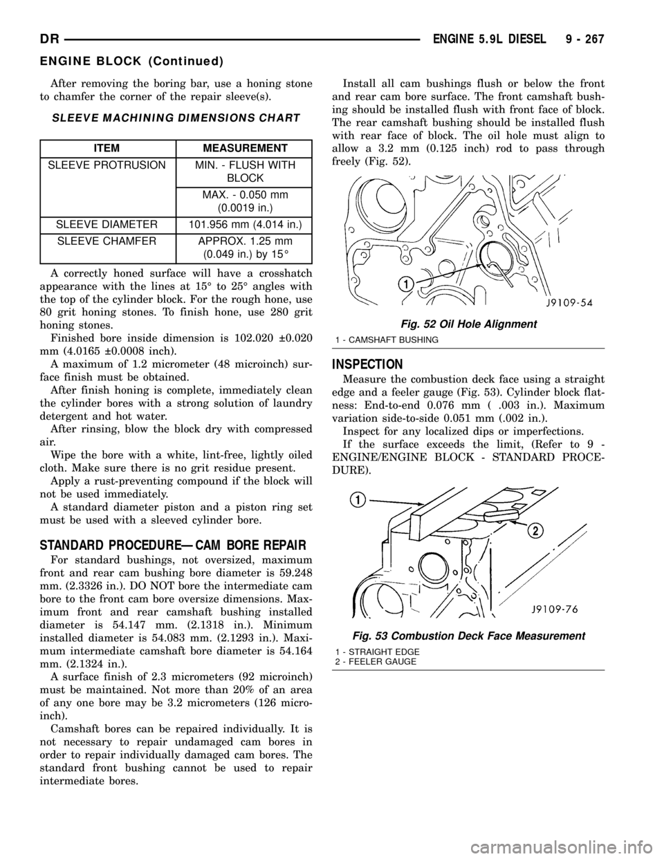
freely (Fig. 52).
INSPECTION
Measure the combustion deck face using a straight
edge and a feeler gauge (Fig. 53). Cylinder block flat-
ness: End-to-end 0.076 mm ( .003 in.). Maximum
variation side-to-side 0.051 mm (.002 in.).
Inspect for any localized dips or imperfections.
If the surface exceeds the limit, (Refer to 9 -
ENGINE/ENGINE BLOCK - STANDARD PROCE-
DURE).
Fig. 52 Oil Hole Alignment
1 - CAMSHAFT BUSHING
Fig. 53 Combustion Deck Face Measurement
1 - STRAIGHT EDGE
2 - FEELER GAUGE
DRENGINE 5.9L DIESEL 9 - 267
ENGINE BLOCK (Continued)
Page 1491 of 2627
Inspect the cylinder bores for damage or excessive
wear.
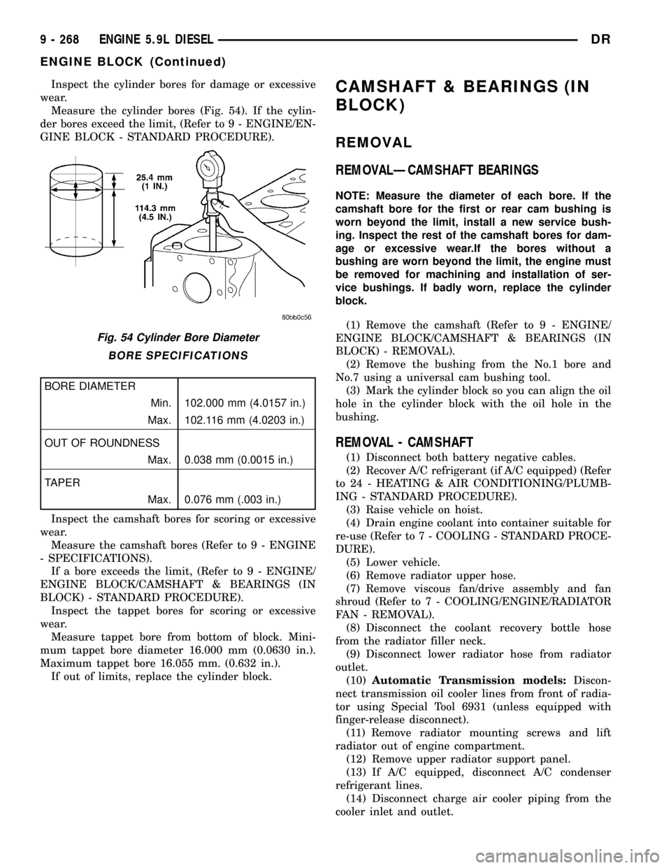
Measure the cylinder bores (Fig. 54). If the cylin-
der bores exceed the limit, (Refer to 9 - ENGINE/EN-
GINE BLOCK - STANDARD PROCEDURE).
BORE SPECIFICATIONS
BORE DIAMETER
Min. 102.000 mm (4.0157 in.)
Max. 102.116 mm (4.0203 in.)
OUT OF ROUNDNESS
Max. 0.038 mm (0.0015 in.)
TAPER
Max. 0.076 mm (.003 in.)
Inspect the camshaft bores for scoring or excessive
wear.
Measure the camshaft bores (Refer to 9 - ENGINE
- SPECIFICATIONS).
If a bore exceeds the limit, (Refer to 9 - ENGINE/
ENGINE BLOCK/CAMSHAFT & BEARINGS (IN
BLOCK) - STANDARD PROCEDURE).
Inspect the tappet bores for scoring or excessive
wear.
Measure tappet bore from bottom of block. Mini-
mum tappet bore diameter 16.000 mm (0.0630 in.).
Maximum tappet bore 16.055 mm. (0.632 in.).
If out of limits, replace the cylinder block.
CAMSHAFT & BEARINGS (IN
BLOCK)
REMOVAL
REMOVALÐCAMSHAFT BEARINGS
NOTE: Measure the diameter of each bore. If the
camshaft bore for the first or rear cam bushing is
worn beyond the limit, install a new service bush-
ing. Inspect the rest of the camshaft bores for dam-
age or excessive wear.If the bores without a
bushing are worn beyond the limit, the engine must
be removed for machining and installation of ser-
vice bushings. If badly worn, replace the cylinder
block.
(1) Remove the camshaft (Refer to 9 - ENGINE/
ENGINE BLOCK/CAMSHAFT & BEARINGS (IN
BLOCK) - REMOVAL).
(2) Remove the bushing from the No.1 bore and
No.7 using a universal cam bushing tool.
(3) Mark the cylinder block so you can align the oil
hole in the cylinder block with the oil hole in the
bushing.
REMOVAL - CAMSHAFT
(1) Disconnect both battery negative cables.
(2) Recover A/C refrigerant (if A/C equipped) (Refer
to 24 - HEATING & AIR CONDITIONING/PLUMB-
ING - STANDARD PROCEDURE).
(3) Raise vehicle on hoist.
(4) Drain engine coolant into container suitable for
re-use (Refer to 7 - COOLING - STANDARD PROCE-
DURE).
(5) Lower vehicle.
(6) Remove radiator upper hose.
(7) Remove viscous fan/drive assembly and fan
shroud (Refer to 7 - COOLING/ENGINE/RADIATOR
FAN - REMOVAL).
(8) Disconnect the coolant recovery bottle hose
from the radiator filler neck.
(9) Disconnect lower radiator hose from radiator
outlet.
(10)Automatic Transmission models:Discon-
nect transmission oil cooler lines from front of radia-
tor using Special Tool 6931 (unless equipped with
finger-release disconnect).
(11) Remove radiator mounting screws and lift
radiator out of engine compartment.
(12) Remove upper radiator support panel.
(13) If A/C equipped, disconnect A/C condenser
refrigerant lines.
(14) Disconnect charge air cooler piping from the
cooler inlet and outlet.
Fig. 54 Cylinder Bore Diameter
9 - 268 ENGINE 5.9L DIESELDR
ENGINE BLOCK (Continued)
Page 1492 of 2627
(15) Remove the two charge air cooler mounting
bolts.
(16) Remove charge air cooler (and A/C condenser
if equipped) from vehicle.
(17) Remove accessory drive belt (Refer to 7 -
COOLING/ACCESSORY DRIVE/DRIVE BELTS -
REMOVAL).
(18) Remove accessory drive belt tensioner.
(19) Remove the fan support/hub assembly.
(20) Remove crankshaft damper and speed indica-
tor ring (Refer to 9 - ENGINE/ENGINE BLOCK/VI-
BRATION DAMPER - REMOVAL).
(21) Remove the gear cover-to-housing bolts and
gently pry the cover away from the housing, taking
care not to mar the sealing surfaces. Remove dust
seal with cover.
(22) Using Special Tool 7471±B Crankshaft Bar-
ring Tool, rotate the crankshaft to align the timing
marks on the crankshaft and the camshaft gears.
(23) Remove the cylinder head cover (Refer to 9 -
ENGINE/CYLINDER HEAD/CYLINDER HEAD
COVER(S) - REMOVAL).
(24) Remove the rocker arms, cross heads, and
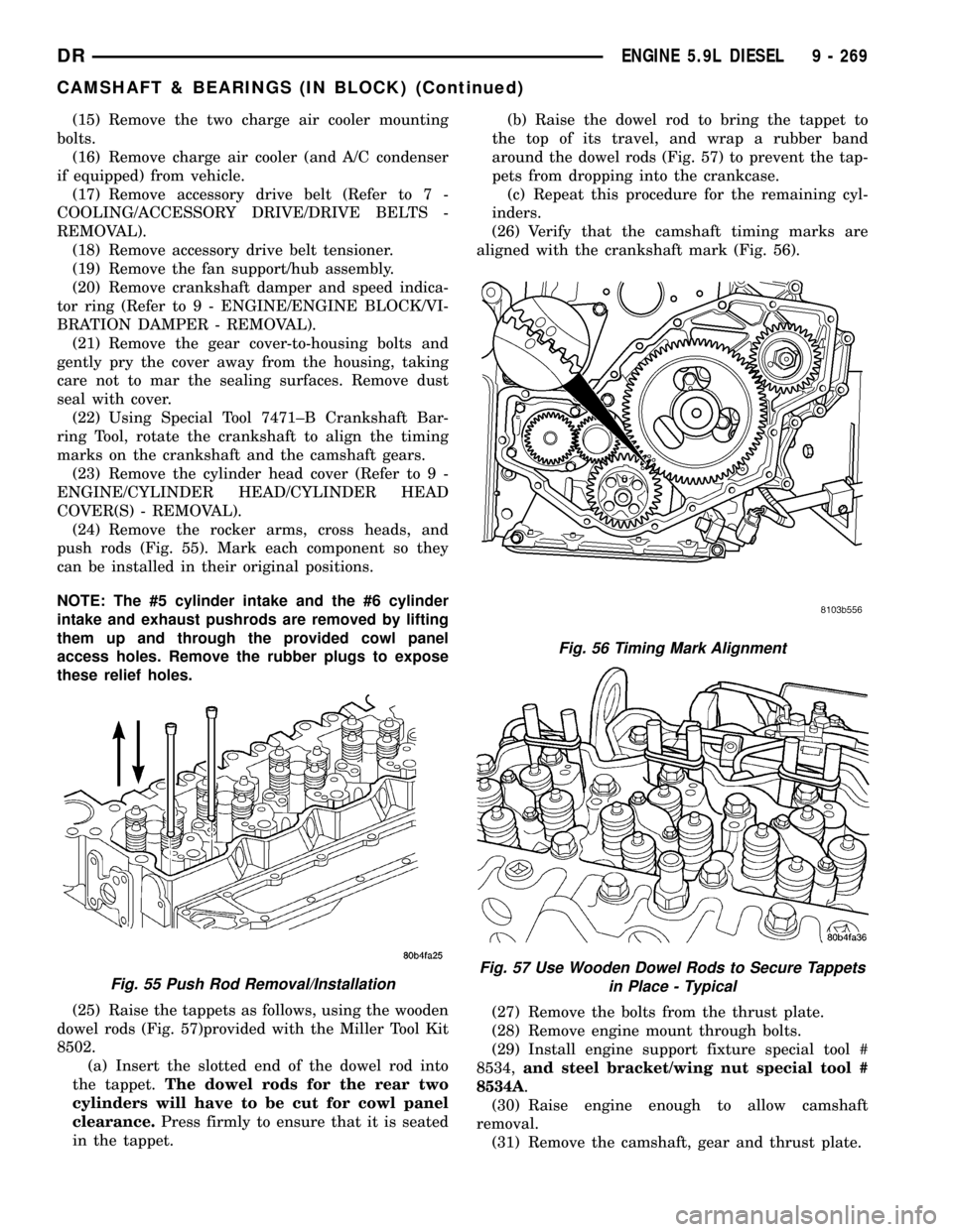
push rods (Fig. 55). Mark each component so they
can be installed in their original positions.
NOTE: The #5 cylinder intake and the #6 cylinder
intake and exhaust pushrods are removed by lifting
them up and through the provided cowl panel
access holes. Remove the rubber plugs to expose
these relief holes.
(25) Raise the tappets as follows, using the wooden
dowel rods (Fig. 57)provided with the Miller Tool Kit
8502.
(a) Insert the slotted end of the dowel rod into
the tappet.The dowel rods for the rear two
cylinders will have to be cut for cowl panel
clearance.Press firmly to ensure that it is seated
in the tappet.(b) Raise the dowel rod to bring the tappet to
the top of its travel, and wrap a rubber band
around the dowel rods (Fig. 57) to prevent the tap-
pets from dropping into the crankcase.
(c) Repeat this procedure for the remaining cyl-
inders.
(26) Verify that the camshaft timing marks are
aligned with the crankshaft mark (Fig. 56).
(27) Remove the bolts from the thrust plate.
(28) Remove engine mount through bolts.
(29) Install engine support fixture special tool #
8534,and steel bracket/wing nut special tool #
8534A.
(30) Raise engine enough to allow camshaft
removal.
(31) Remove the camshaft, gear and thrust plate.
Fig. 55 Push Rod Removal/Installation
Fig. 56 Timing Mark Alignment
Fig. 57 Use Wooden Dowel Rods to Secure Tappets
in Place - Typical
DRENGINE 5.9L DIESEL 9 - 269
CAMSHAFT & BEARINGS (IN BLOCK) (Continued)
Page 1494 of 2627
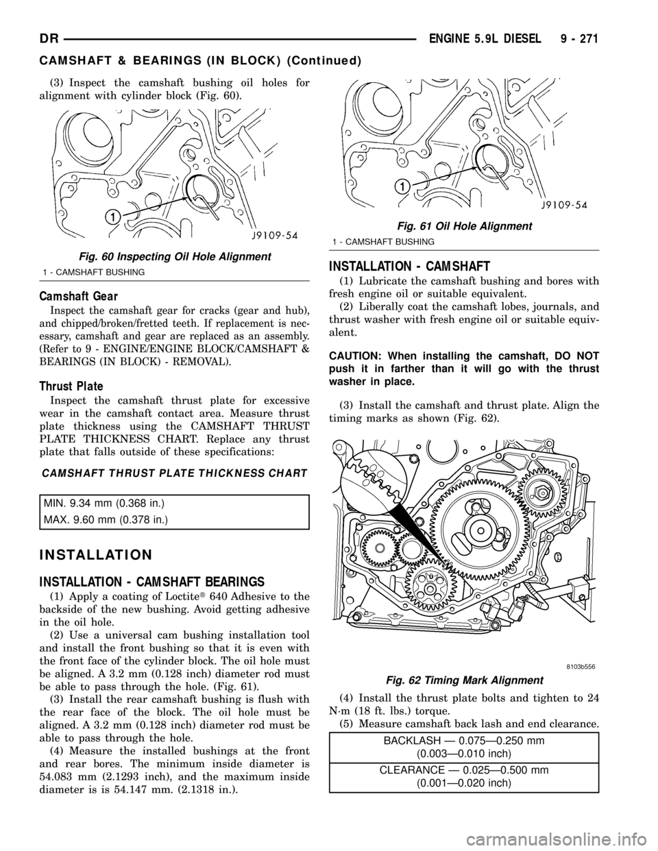
(3) Inspect the camshaft bushing oil holes for
alignment with cylinder block (Fig. 60).
Camshaft Gear
Inspect the camshaft gear for cracks (gear and hub),
and chipped/broken/fretted teeth. If replacement is nec-
essary, camshaft and gear are replaced as an assembly.
(Refer to 9 - ENGINE/ENGINE BLOCK/CAMSHAFT &
BEARINGS (IN BLOCK) - REMOVAL).
Thrust Plate
Inspect the camshaft thrust plate for excessive
wear in the camshaft contact area. Measure thrust
plate thickness using the CAMSHAFT THRUST
PLATE THICKNESS CHART. Replace any thrust
plate that falls outside of these specifications:
CAMSHAFT THRUST PLATE THICKNESS CHART
MIN. 9.34 mm (0.368 in.)
MAX. 9.60 mm (0.378 in.)
INSTALLATION
INSTALLATION - CAMSHAFT BEARINGS
(1) Apply a coating of Loctitet640 Adhesive to the
backside of the new bushing. Avoid getting adhesive
in the oil hole.
(2) Use a universal cam bushing installation tool
and install the front bushing so that it is even with
the front face of the cylinder block. The oil hole must
be aligned. A 3.2 mm (0.128 inch) diameter rod must
be able to pass through the hole. (Fig. 61).
(3) Install the rear camshaft bushing is flush with
the rear face of the block. The oil hole must be
aligned. A 3.2 mm (0.128 inch) diameter rod must be
able to pass through the hole.
(4) Measure the installed bushings at the front
and rear bores. The minimum inside diameter is
54.083 mm (2.1293 inch), and the maximum inside
diameter is is 54.147 mm. (2.1318 in.).
INSTALLATION - CAMSHAFT
(1) Lubricate the camshaft bushing and bores with
fresh engine oil or suitable equivalent.
(2) Liberally coat the camshaft lobes, journals, and
thrust washer with fresh engine oil or suitable equiv-
alent.
CAUTION: When installing the camshaft, DO NOT
push it in farther than it will go with the thrust
washer in place.
(3) Install the camshaft and thrust plate. Align the
timing marks as shown (Fig. 62).
(4) Install the thrust plate bolts and tighten to 24
N´m (18 ft. lbs.) torque.
(5) Measure camshaft back lash and end clearance.
BACKLASH Ð 0.075Ð0.250 mm
(0.003Ð0.010 inch)
CLEARANCE Ð 0.025Ð0.500 mm
(0.001Ð0.020 inch)
Fig. 60 Inspecting Oil Hole Alignment
1 - CAMSHAFT BUSHING
Fig. 61 Oil Hole Alignment
1 - CAMSHAFT BUSHING
Fig. 62 Timing Mark Alignment
DRENGINE 5.9L DIESEL 9 - 271
CAMSHAFT & BEARINGS (IN BLOCK) (Continued)
Page 1495 of 2627
(6) Remove the wooden dowel rods and rubber
bands from the tappets.
(7) Lubricate the push rods with engine oil and
install in their original location.Verify that they
are seated in the tappets.
(8) Lubricate the valve tips with engine oil and
install the crossheads in their original locations.
(9) Lubricate the crossheads and push rod sockets
with engine oil and install the rocker arms and ped-
estals in their original locations. Tighten bolts to 36
N´m (27 ft. lbs.) torque.
(10)Verify valve lash adjustment (Refer to 9 -
ENGINE/CYLINDER HEAD/INTAKE/EXHAUST
VALVES & SEATS - STANDARD PROCEDURE).
(11) Install the cylinder head cover and reusable
gasket (Refer to 9 - ENGINE/CYLINDER HEAD/
CYLINDER HEAD COVER(S) - INSTALLATION).
(12) Install gear housing cover (Refer to 9 -
ENGINE/VALVE TIMING/GEAR HOUSING COVER
- INSTALLATION). Install front crankshaft dust
seal.
(13) Install the crankshaft damper with the speed
indicator ring (Refer to 9 - ENGINE/ENGINE
BLOCK/VIBRATION DAMPER - INSTALLATION).
(14) Install the fan support/hub assembly Refer to
(Refer to 7 - COOLING/ENGINE/RADIATOR FAN -
INSTALLATION).
(15) Install the power steering pump.
(16) Install accessory drive belt tensioner. Torque
bolt to 43 Nm (32 ft. lbs.).
(17) Install the accessory drive belt (Refer to 7 -
COOLING/ACCESSORY DRIVE/DRIVE BELTS -
INSTALLATION).
(18) Install the charge air cooler (with a/c con-
denser and auxiliary transmission oil cooler, if
equipped) and tighten the mounting bolts to 2 N´m
(17 in. lbs.) torque.
(19) Connect charge air cooler inlet and outlet
pipes. Tighten clamps to 11 N´m (95 in. lbs.) torque.
(20) Install the radiator upper support panel.
(21) Close radiator petcock and lower the radiator
into the engine compartment. Tighten the mounting
bolts to 11 N´m (95 in. lbs.) torque.
(22) Raise vehicle on hoist.
(23) Connect radiator lower hose and install
clamp.
(24) Connect transmission auxiliary oil cooler lines
(if equipped).
(25) Lower vehicle.
(26) Install the fan shroud and tighten the mount-
ing screws to 6 N´m (50 in. lbs.) torque.
(27) Install the electronically controlled viscous
fan/drive assembly. Connect harness connector.(Refer
to 7 - COOLING/ENGINE/RADIATOR FAN -
INSTALLATION).(28) Install the coolant recovery and windshield
washer fluid reservoirs to the fan shroud.
(29) Connect the coolant recovery hose to the radi-
ator filler neck.
(30) Add engine coolant (Refer to 7 - COOLING -
STANDARD PROCEDURE).
(31) Charge A/C system with refrigerant (if A/C
equipped) (Refer to 24 - HEATING & AIR CONDI-
TIONING/PLUMBING - STANDARD PROCEDURE).
(32) Connect the battery negative cables.
(33) Start engine and check for engine oil and cool-
ant leaks.
CONNECTING ROD BEARINGS
STANDARD PROCEDURE - CONNECTING ROD
BEARING AND CRANKSHAFT JOURNAL
CLEARANCE
(1) Measure the connecting rod bore with bearings
removedand the bolts tightened to 100 N´m (73 ft.
lbs.) torque..
(2) Measure the connecting rod bore with the bear-
ingsinstalledand the bolts tightened to 100 N´m
(73 ft. lbs.) torque.
Measure within 20É arc from each side of the part-
ing line. Also measure 90É from parting line.
Record the smallest and largest diameter.
Measure the diameter of the rod journal at the
location shown (Fig. 63). Calculate the average diam-
eter for each side of the journal.
Determine minimum bearing clearance by calculat-
ing the differance between the smallest connecting
rod bore diameter with the bearing installed and the
average diameter for each side of the crankshaft jour-
nal.
Determine the maximum bearing clearance by cal-
culating the difference between the largest connect-
ing rod bore diameter and the average diameter with
the bearing installed for each side of the crankshaft
journal.
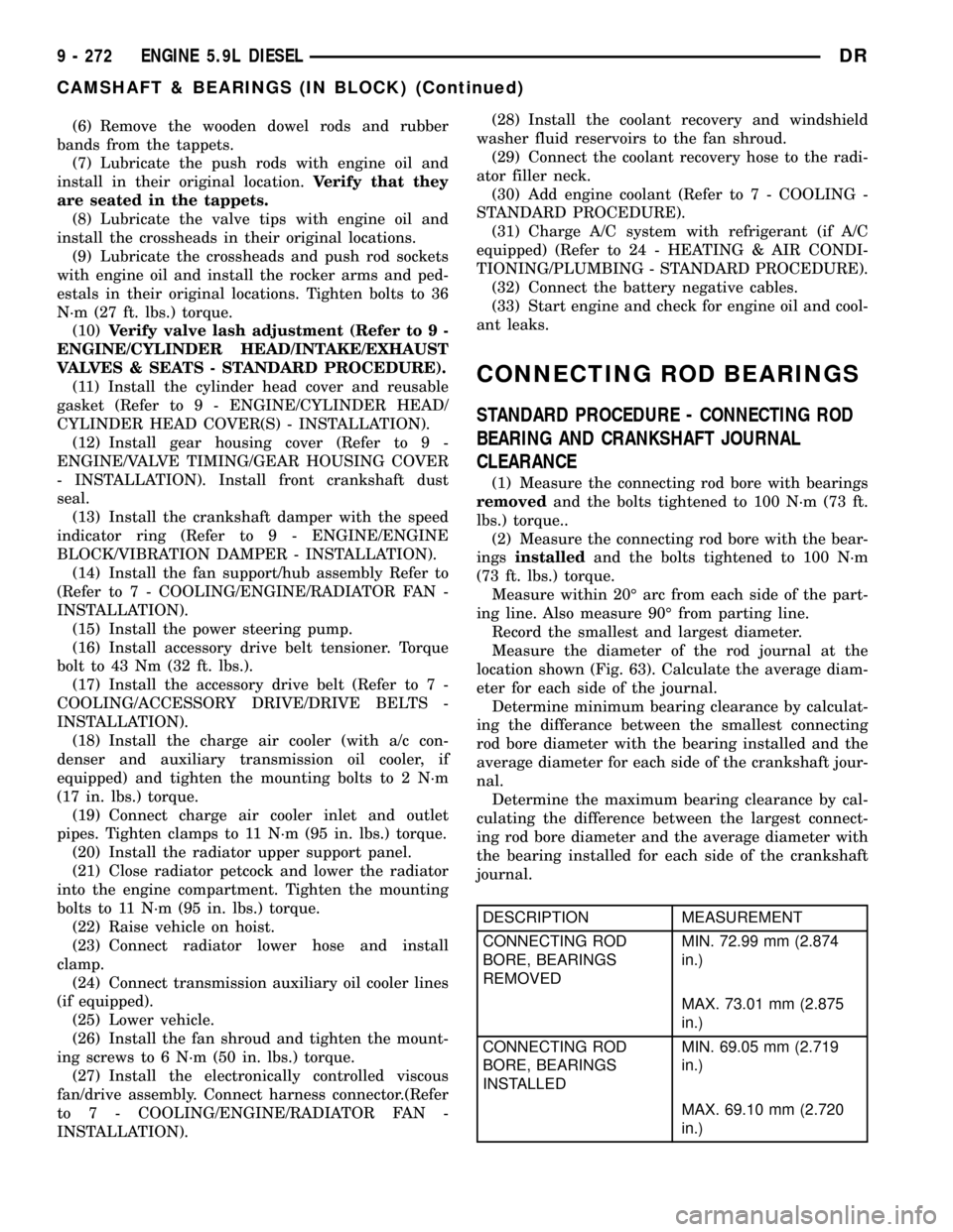
DESCRIPTION MEASUREMENT
CONNECTING ROD
BORE, BEARINGS
REMOVEDMIN. 72.99 mm (2.874
in.)
MAX. 73.01 mm (2.875
in.)
CONNECTING ROD
BORE, BEARINGS
INSTALLEDMIN. 69.05 mm (2.719
in.)
MAX. 69.10 mm (2.720
in.)
9 - 272 ENGINE 5.9L DIESELDR
CAMSHAFT & BEARINGS (IN BLOCK) (Continued)
Page 1500 of 2627
(7) Install the flywheel or converter drive plate.
Tighten the bolts to 137 N´m (101 ft. lbs.) torque.
(8) Install the clutch cover and disc (if equipped)
(Refer to 6 - CLUTCH/CLUTCH DISC - INSTALLA-
TION).
(9) Install the transmission and transfer case (if
equipped).
(10) Lower vehicle.
(11) Connect battery negative cables.
(12) Check engine oil level and adjust, if necessary.
(13) Start engine and check for oil leaks.
CRANKSHAFT REAR OIL SEAL
RETAINER
REMOVAL
(1) Disconnect the battery negative cables.
(2) Raise vehicle on hoist.
(3) Remove the oil pan drain plug and drain the
engine oil. Re-install plug and torque to 50 N´m (44
ft. lbs.) torque.
(4) Remove transmission and transfer case (if
equipped) from vehicle.
(5)
Remove flywheel or torque converter drive plate.
(6) Disconnect starter cables from starter motor.
(7) Remove starter motor (Refer to 8 - ELECTRI-
CAL/STARTING/STARTER MOTOR - REMOVAL)
and transmission adapter plate assembly.
(8) Remove four (4) oil pan rear bolts. Slide a
feeler gauge between the seal retainer and oil pan
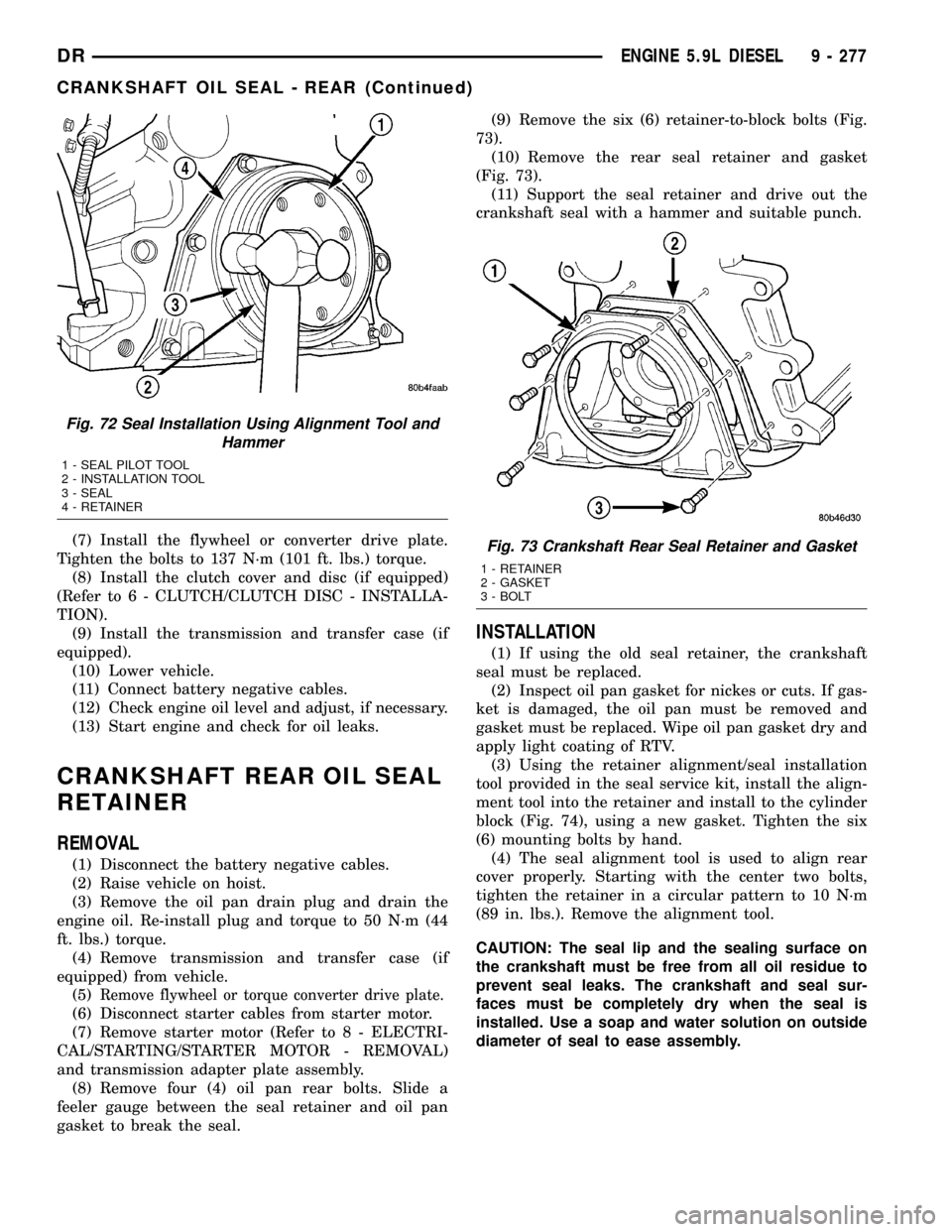
gasket to break the seal.(9) Remove the six (6) retainer-to-block bolts (Fig.
73).
(10) Remove the rear seal retainer and gasket
(Fig. 73).
(11) Support the seal retainer and drive out the
crankshaft seal with a hammer and suitable punch.
INSTALLATION
(1) If using the old seal retainer, the crankshaft
seal must be replaced.
(2) Inspect oil pan gasket for nickes or cuts. If gas-
ket is damaged, the oil pan must be removed and
gasket must be replaced. Wipe oil pan gasket dry and
apply light coating of RTV.
(3) Using the retainer alignment/seal installation
tool provided in the seal service kit, install the align-
ment tool into the retainer and install to the cylinder
block (Fig. 74), using a new gasket. Tighten the six
(6) mounting bolts by hand.
(4) The seal alignment tool is used to align rear
cover properly. Starting with the center two bolts,
tighten the retainer in a circular pattern to 10 N´m
(89 in. lbs.). Remove the alignment tool.
CAUTION: The seal lip and the sealing surface on
the crankshaft must be free from all oil residue to
prevent seal leaks. The crankshaft and seal sur-
faces must be completely dry when the seal is
installed. Use a soap and water solution on outside
diameter of seal to ease assembly.
Fig. 72 Seal Installation Using Alignment Tool and
Hammer
1 - SEAL PILOT TOOL
2 - INSTALLATION TOOL
3 - SEAL
4 - RETAINER
Fig. 73 Crankshaft Rear Seal Retainer and Gasket
1 - RETAINER
2 - GASKET
3 - BOLT
DRENGINE 5.9L DIESEL 9 - 277
CRANKSHAFT OIL SEAL - REAR (Continued)
Page 1502 of 2627
SOLID LIFTERS/TAPPETS
REMOVAL
NOTE: This procedure requires use of Miller Tool
8502 Tappet Replacement Kit.
(1) Remove camshaft (Refer to 9 - ENGINE/EN-
GINE BLOCK/CAMSHAFT & BEARINGS (IN
BLOCK) - REMOVAL).
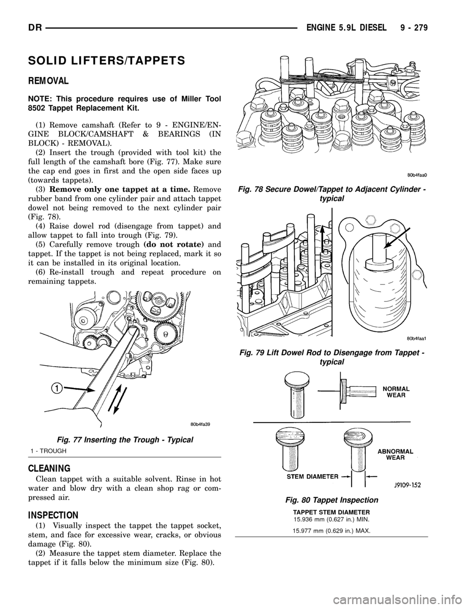
(2) Insert the trough (provided with tool kit) the
full length of the camshaft bore (Fig. 77). Make sure
the cap end goes in first and the open side faces up
(towards tappets).
(3)Remove only one tappet at a time.Remove
rubber band from one cylinder pair and attach tappet
dowel not being removed to the next cylinder pair
(Fig. 78).
(4) Raise dowel rod (disengage from tappet) and
allow tappet to fall into trough (Fig. 79).
(5) Carefully remove trough(do not rotate)and
tappet. If the tappet is not being replaced, mark it so
it can be installed in its original location.
(6) Re-install trough and repeat procedure on
remaining tappets.
CLEANING
Clean tappet with a suitable solvent. Rinse in hot
water and blow dry with a clean shop rag or com-
pressed air.
INSPECTION
(1) Visually inspect the tappet the tappet socket,
stem, and face for excessive wear, cracks, or obvious
damage (Fig. 80).
(2) Measure the tappet stem diameter. Replace the
tappet if it falls below the minimum size (Fig. 80).
Fig. 77 Inserting the Trough - Typical
1 - TROUGH
Fig. 78 Secure Dowel/Tappet to Adjacent Cylinder -
typical
Fig. 79 Lift Dowel Rod to Disengage from Tappet -
typical
Fig. 80 Tappet Inspection
TAPPET STEM DIAMETER
15.936 mm (0.627 in.) MIN.
15.977 mm (0.629 in.) MAX.
DRENGINE 5.9L DIESEL 9 - 279
Page 1504 of 2627
PISTON & CONNECTING ROD
DESCRIPTION
PISTONS
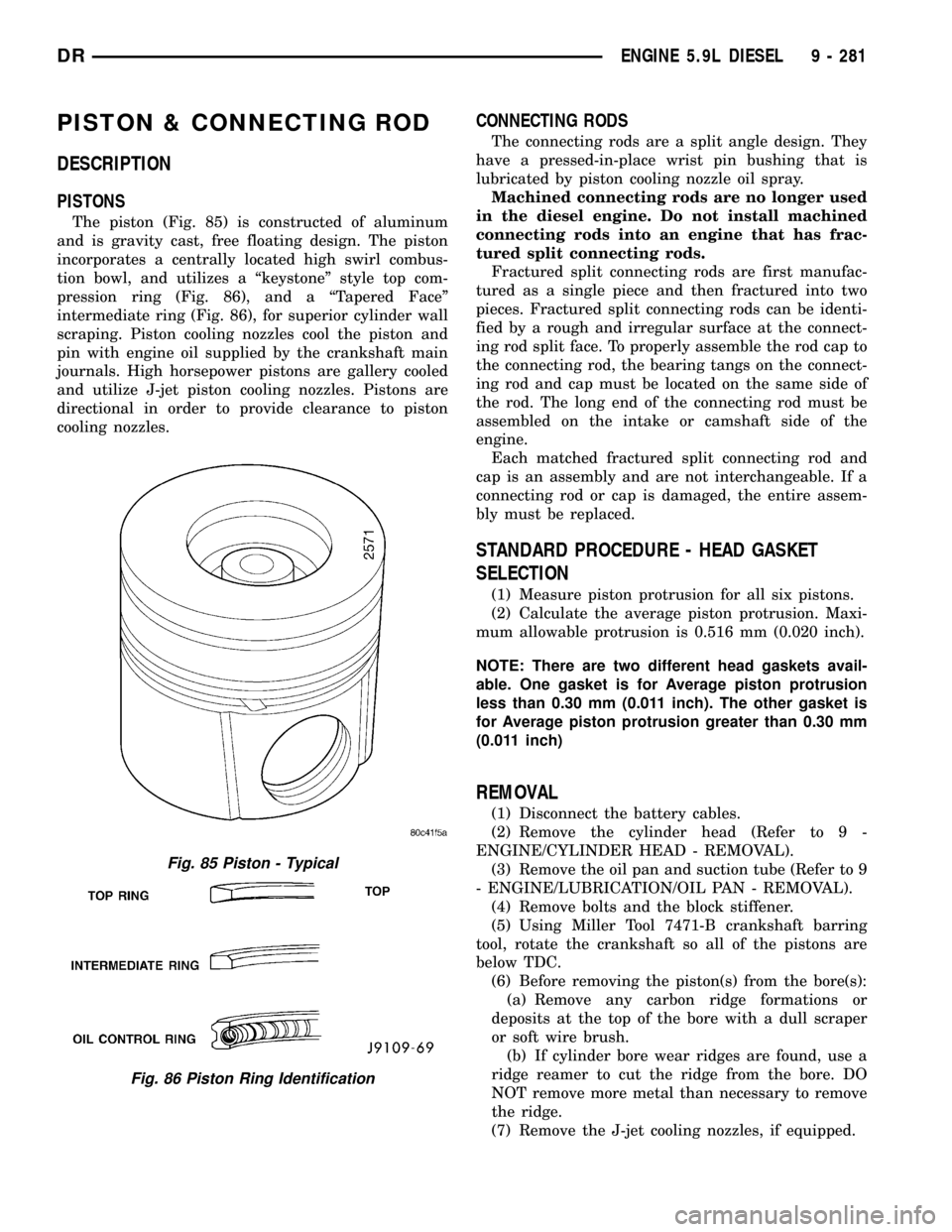
The piston (Fig. 85) is constructed of aluminum
and is gravity cast, free floating design. The piston
incorporates a centrally located high swirl combus-
tion bowl, and utilizes a ªkeystoneº style top com-
pression ring (Fig. 86), and a ªTapered Faceº
intermediate ring (Fig. 86), for superior cylinder wall
scraping. Piston cooling nozzles cool the piston and
pin with engine oil supplied by the crankshaft main
journals. High horsepower pistons are gallery cooled
and utilize J-jet piston cooling nozzles. Pistons are
directional in order to provide clearance to piston
cooling nozzles.
CONNECTING RODS
The connecting rods are a split angle design. They
have a pressed-in-place wrist pin bushing that is
lubricated by piston cooling nozzle oil spray.
Machined connecting rods are no longer used
in the diesel engine. Do not install machined
connecting rods into an engine that has frac-
tured split connecting rods.
Fractured split connecting rods are first manufac-
tured as a single piece and then fractured into two
pieces. Fractured split connecting rods can be identi-
fied by a rough and irregular surface at the connect-
ing rod split face. To properly assemble the rod cap to
the connecting rod, the bearing tangs on the connect-
ing rod and cap must be located on the same side of
the rod. The long end of the connecting rod must be
assembled on the intake or camshaft side of the
engine.
Each matched fractured split connecting rod and
cap is an assembly and are not interchangeable. If a
connecting rod or cap is damaged, the entire assem-
bly must be replaced.
STANDARD PROCEDURE - HEAD GASKET
SELECTION
(1) Measure piston protrusion for all six pistons.
(2) Calculate the average piston protrusion. Maxi-
mum allowable protrusion is 0.516 mm (0.020 inch).
NOTE: There are two different head gaskets avail-
able. One gasket is for Average piston protrusion
less than 0.30 mm (0.011 inch). The other gasket is
for Average piston protrusion greater than 0.30 mm
(0.011 inch)
REMOVAL
(1) Disconnect the battery cables.
(2) Remove the cylinder head (Refer to 9 -
ENGINE/CYLINDER HEAD - REMOVAL).
(3) Remove the oil pan and suction tube (Refer to 9
- ENGINE/LUBRICATION/OIL PAN - REMOVAL).
(4) Remove bolts and the block stiffener.
(5) Using Miller Tool 7471-B crankshaft barring
tool, rotate the crankshaft so all of the pistons are
below TDC.
(6) Before removing the piston(s) from the bore(s):
(a) Remove any carbon ridge formations or
deposits at the top of the bore with a dull scraper
or soft wire brush.
(b) If cylinder bore wear ridges are found, use a
ridge reamer to cut the ridge from the bore. DO
NOT remove more metal than necessary to remove
the ridge.
(7) Remove the J-jet cooling nozzles, if equipped.
Fig. 85 Piston - Typical
Fig. 86 Piston Ring Identification
DRENGINE 5.9L DIESEL 9 - 281