1998 DODGE RAM 1500 Replace air cleaner
[x] Cancel search: Replace air cleanerPage 1428 of 2627
ENGINE BLOCK
CLEANING
Thoroughly clean the oil pan and engine block gas-
ket surfaces.
Use compressed air to clean out:
²The galley at the oil filter adaptor hole.
²The front and rear oil galley holes.
²The feed holes for the crankshaft main bearings.
Once the block has been completely cleaned, apply
Loctite PST pipe sealant with Teflon 592 to the
threads of the front and rear oil galley plugs. Tighten
the 1/4 inch NPT plugs to 20 N´m (177 in. lbs.)
torque. Tighten the 3/8 inch NPT plugs to 27 N´m
(240 in. lbs.) torque.
INSPECTION
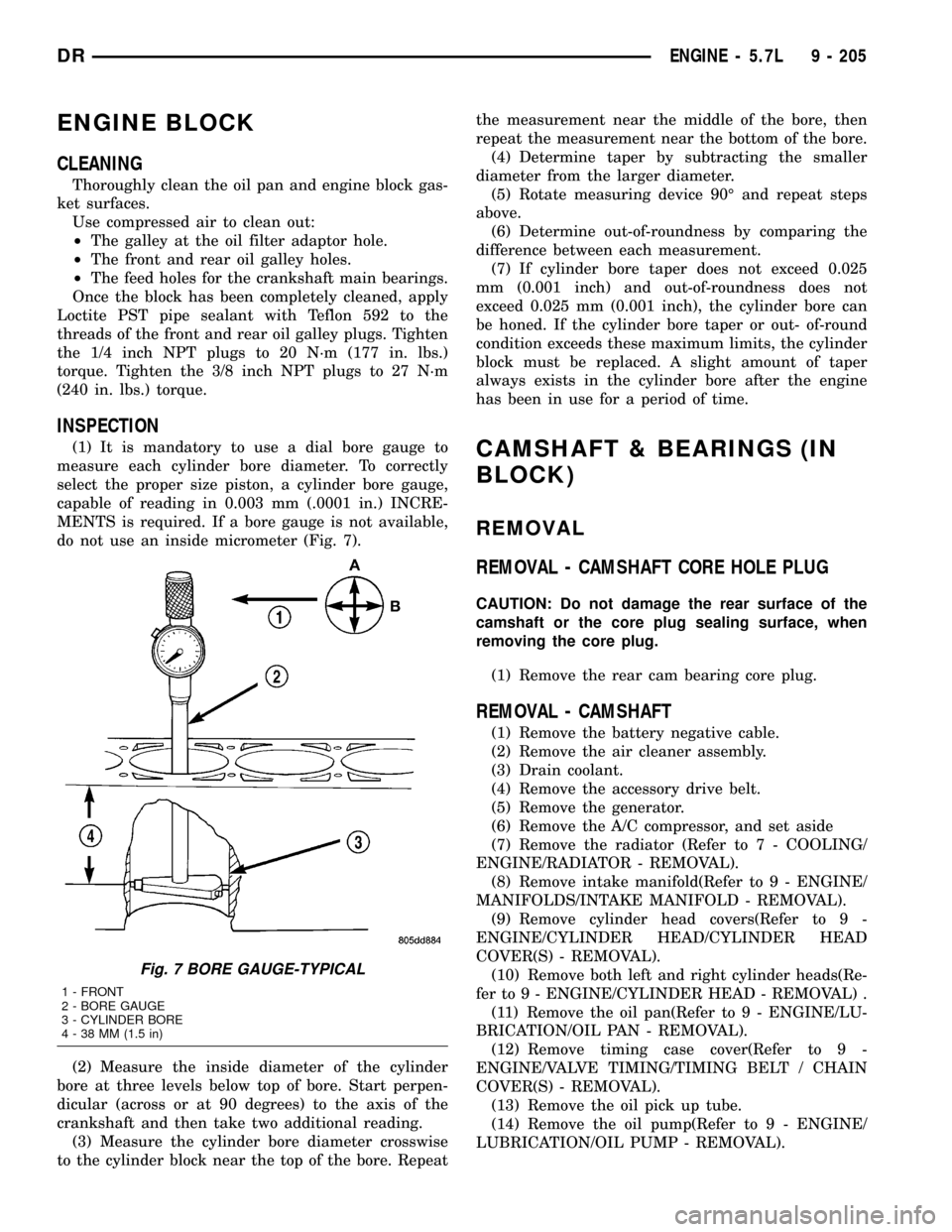
(1) It is mandatory to use a dial bore gauge to
measure each cylinder bore diameter. To correctly
select the proper size piston, a cylinder bore gauge,
capable of reading in 0.003 mm (.0001 in.) INCRE-
MENTS is required. If a bore gauge is not available,
do not use an inside micrometer (Fig. 7).
(2) Measure the inside diameter of the cylinder
bore at three levels below top of bore. Start perpen-
dicular (across or at 90 degrees) to the axis of the
crankshaft and then take two additional reading.
(3) Measure the cylinder bore diameter crosswise
to the cylinder block near the top of the bore. Repeatthe measurement near the middle of the bore, then
repeat the measurement near the bottom of the bore.
(4) Determine taper by subtracting the smaller
diameter from the larger diameter.
(5) Rotate measuring device 90É and repeat steps
above.
(6) Determine out-of-roundness by comparing the
difference between each measurement.
(7) If cylinder bore taper does not exceed 0.025
mm (0.001 inch) and out-of-roundness does not
exceed 0.025 mm (0.001 inch), the cylinder bore can
be honed. If the cylinder bore taper or out- of-round
condition exceeds these maximum limits, the cylinder
block must be replaced. A slight amount of taper
always exists in the cylinder bore after the engine
has been in use for a period of time.CAMSHAFT & BEARINGS (IN
BLOCK)
REMOVAL
REMOVAL - CAMSHAFT CORE HOLE PLUG
CAUTION: Do not damage the rear surface of the
camshaft or the core plug sealing surface, when
removing the core plug.
(1) Remove the rear cam bearing core plug.
REMOVAL - CAMSHAFT
(1) Remove the battery negative cable.
(2) Remove the air cleaner assembly.
(3) Drain coolant.
(4) Remove the accessory drive belt.
(5) Remove the generator.
(6) Remove the A/C compressor, and set aside
(7) Remove the radiator (Refer to 7 - COOLING/
ENGINE/RADIATOR - REMOVAL).
(8) Remove intake manifold(Refer to 9 - ENGINE/
MANIFOLDS/INTAKE MANIFOLD - REMOVAL).
(9) Remove cylinder head covers(Refer to 9 -
ENGINE/CYLINDER HEAD/CYLINDER HEAD
COVER(S) - REMOVAL).
(10) Remove both left and right cylinder heads(Re-
fer to 9 - ENGINE/CYLINDER HEAD - REMOVAL) .
(11) Remove the oil pan(Refer to 9 - ENGINE/LU-
BRICATION/OIL PAN - REMOVAL).
(12) Remove timing case cover(Refer to 9 -
ENGINE/VALVE TIMING/TIMING BELT / CHAIN
COVER(S) - REMOVAL).
(13) Remove the oil pick up tube.
(14) Remove the oil pump(Refer to 9 - ENGINE/
LUBRICATION/OIL PUMP - REMOVAL).
Fig. 7 BORE GAUGE-TYPICAL
1 - FRONT
2 - BORE GAUGE
3 - CYLINDER BORE
4 - 38 MM (1.5 in)
DRENGINE - 5.7L 9 - 205
Page 1429 of 2627
(15) Remove timing chain(Refer to 9 - ENGINE/
VALVE TIMING/TIMING BELT/CHAIN AND
SPROCKETS - REMOVAL).
(16) Remove camshaft tensioner/thrust plate
assembly.
NOTE: Identify tappets to ensure installation in orig-
inal location.
(17) Remove the retainer assembly and tappets.
(18) Install a long bolt into front of camshaft to aid
in removal of the camshaft. Remove camshaft, being
careful not to damage cam bearings with the cam
lobes.
INSPECTION
(1) The cam bearings are not serviceable. Do not
attempt to replace cam bearings for any reason.
INSTALLATION
INSTALLATION - CAMSHAFT CORE HOLE PLUG
CAUTION: The new core hole plug must be installed
to the proper depth or camshaft damage could
develope. The plug must be installed squarely in
the bore.
(1) Install a new core hole plug at the rear of cam-
shaft, using special tool # 9048. Clean plug and apply
mopartlock and seal adhesive to the edge of the
plug, before installing. The plug must be installed to
a depth of+/-0.25mm from the end of the machined
bevel, that is the end of the bevel that is closest to
the cam bearing.
INSTALLATION - CAMSHAFT
(1) Lubricate camshaft lobes and camshaft bearing
journals and insert the camshaft
(2) Install camshaft Tensioner plate assembly.
Tighten bolts to 28 N´m (250 in. lbs.) torque.
(3) Install timing chain and sprockets(Refer to 9 -
ENGINE/VALVE TIMING/TIMING BELT/CHAIN
AND SPROCKETS - INSTALLATION) .
(4) Measure camshaft end play(Refer to 9 -
ENGINE - SPECIFICATIONS). If not within limits
install a new thrust plate.
(5) Install the oil pump(Refer to 9 - ENGINE/LU-
BRICATION/OIL PUMP - INSTALLATION).
(6) Install the oil pick up tube.
(7) Each tappet reused must be installed in the
same position from which it was removed.When
camshaft is replaced, all of the tappets must be
replaced.(8) Install the tappets and retainer assembly(Refer
to 9 - ENGINE/ENGINE BLOCK/HYDRAULIC LIFT-
ERS (CAM IN BLOCK) - INSTALLATION).
(9) Install both left and right cylinder heads(Refer
to 9 - ENGINE/CYLINDER HEAD - INSTALLA-
TION) .
(10) Install pushrods
(11) Install rocker arms(Refer to 9 - ENGINE/CYL-
INDER HEAD/ROCKER ARM / ADJUSTER ASSY -
INSTALLATION).
(12) Install timing case cover(Refer to 9 -
ENGINE/VALVE TIMING/TIMING BELT / CHAIN
COVER(S) - INSTALLATION).
(13) Install the oil pan(Refer to 9 - ENGINE/LU-
BRICATION/OIL PAN - INSTALLATION).
(14) Install cylinder head covers(Refer to 9 -
ENGINE/CYLINDER HEAD/CYLINDER HEAD
COVER(S) - INSTALLATION).
(15) Install intake manifold(Refer to 9 - ENGINE/
MANIFOLDS/INTAKE MANIFOLD - INSTALLA-
TION).
(16) Install the A/C compressor, and set aside
(17) Install the generator.
(18) Install the accessory drive belt.
(19) Install the radiator (Refer to 7 - COOLING/
ENGINE/RADIATOR - INSTALLATION).
(20) Install the air cleaner assembly.
(21) Install the battery negative cable.
(22) Refill coolant.
(23) Refill engine oil.
(24) Start engine and check for leaks.
CRANKSHAFT
REMOVAL
(1) Remove the vibration damper (Refer to 9 -
ENGINE/ENGINE BLOCK/VIBRATION DAMPER -
REMOVAL).
(2) Remove the oil pan(Refer to 9 - ENGINE/LU-
BRICATION/OIL PAN - REMOVAL).
(3) Remove the oil pump pickup.
(4) Remove the windage tray/oil pan gasket.
(5) Remove the timing chain cover(Refer to 9 -
ENGINE/VALVE TIMING/TIMING BELT / CHAIN
COVER(S) - REMOVAL).
(6) Remove the oil pump(Refer to 9 - ENGINE/LU-
BRICATION/OIL PUMP - REMOVAL).
(7) Remove the timing drive(Refer to 9 - ENGINE/
VALVE TIMING/TIMING BELT/CHAIN AND
SPROCKETS - REMOVAL).
(8) Identify rod bearing caps before removal.
Remove rod bearing caps with bearings.
(9) Identify main bearing caps before removal.
Remove main bearing caps and bearings one at a
time.
9 - 206 ENGINE - 5.7LDR
CAMSHAFT & BEARINGS (IN BLOCK) (Continued)
Page 1459 of 2627
DIAGNOSIS AND TESTINGÐSMOKE DIAGNOSIS CHARTS
The following charts include possible causes and cor-
rections forexcess or abnormalexhaust smoke. Smallamounts of exhaust smoke (at certain times) are to be
considered normal for a diesel powered engine.
EXCESSIVE BLACK SMOKE
POSSIBLE CAUSE CORRECTION
Air filter dirty or plugged. Check Filter MinderTat air filter (Refer to 9 - ENGINE/
AIR INTAKE SYSTEM/AIR CLEANER ELEMENT -
REMOVAL).
Air intake system restricted. Check entire air intake system including all hoses and
tubes for restrictions, collapsed parts or damage.
Repair/replace as necessary.
Air Leak in Intake System. Check entire air intake system including all hoses and
tubes for cracks, loose clamps and/or holes in rubber
ducts. Also check intake manifold for loose mounting
hardware.
Diagnostic Trouble Codes (DTC's) active or multiple,
intermittent DTC's.Refer to Powertrain Diagnostic Procedures Information.
Engine Control Module (ECM) not calibrated or ECM
has incorrect calibration.Refer to Powertrain Diagnostic Procedures Information.
Exhaust system restriction is above specifications. Check exhaust pipes for damage/restrictions. Repair as
necessary.
Fuel grade is not correct or fuel quality is poor. Temporarily change fuel brands and note condition.
Change brand if necessary.
Fuel injection pump malfunctioning. A DTC may have been set. If so, refer to Powertrain
Diagnostic Procedures Information.
Fuel injector malfunctioning. A DTC may have been set. Perform9Cylinder Cutout
Test9using DRB scan tool to isolate individual
cylinders. Also refer to Powertrain Diagnostic
Procedures Information and, to (Refer to 14 - FUEL
SYSTEM/FUEL INJECTION/FUEL INJECTOR -
DIAGNOSIS AND TESTING).
Fuel return system restricted. Check fuel return lines for restriction (Refer to 14 -
FUEL SYSTEM/FUEL DELIVERY - DIAGNOSIS AND
TESTING).
Intake manifold restricted. Remove restriction.
Manifold Air Pressure (Boost) Sensor or sensor circuit
malfunctioning.A DTC should have been set. Refer to Powertrain
Diagnostic Procedures Information.
Raw fuel in intake manifold. Fuel injectors leaking on engine shutdown. Do Fuel
Injector Test (Refer to 14 - FUEL SYSTEM/FUEL
INJECTION/FUEL INJECTOR - DIAGNOSIS AND
TESTING).
Turbocharger air intake restriction. Remove restriction.
Turbocharger damaged. (Refer to 11 - EXHAUST SYSTEM/TURBOCHARGER
SYSTEM/TURBOCHARGER - INSPECTION).
Turbocharger has excess build up on compressor
wheel and/or diffuser vanes.(Refer to 11 - EXHAUST SYSTEM/TURBOCHARGER
SYSTEM/TURBOCHARGER - CLEANING).
Turbocharger wheel clearance out of specification. (Refer to 11 - EXHAUST SYSTEM/TURBOCHARGER
SYSTEM/TURBOCHARGER - INSPECTION).
9 - 236 ENGINE 5.9L DIESELDR
ENGINE 5.9L DIESEL (Continued)
Page 1461 of 2627
EXCESSIVE BLUE SMOKE
POSSIBLE CAUSE CORRECTION
Dirty air cleaner or restricted turbocharger intake duct. Check Filter MinderTat air filter housing. (Refer to 9 -
ENGINE/AIR INTAKE SYSTEM/AIR CLEANER
ELEMENT - REMOVAL).
Air leak in boost system between turbocharger
compressor outlet and intake manifold.Service air charge system..
Obstruction in exhaust manifold. Remove exhaust manifold and inspect for blockage
(Refer to 9 - ENGINE/MANIFOLDS/EXHAUST
MANIFOLD - REMOVAL).
Restricted turbocharger drain tube. Remove turbocharger drain tube and remove
obstruction.
Crankcase ventilation system plugged. Inspect crankcase ventilation system for function
Valve seals are worn, brittle, or improperly installed. Replace valve stem oil seals (Refer to 9 - ENGINE/
CYLINDER HEAD/INTAKE/EXHAUST VALVES &
SEATS - REMOVAL).
Valve stems and/or guides are worn. Remove valves and inspect valves and guides. (Refer
to 9 - ENGINE/CYLINDER HEAD/INTAKE/EXHAUST
VALVES & SEATS - STANDARD PROCEDURE).
Broken or Improperly installed piston rings. Tear down engine and inspect piston rings.
Excessive piston ring end gap. Remove pistons and measure piston ring end gap
(Refer to 9 - ENGINE/ENGINE BLOCK/PISTON RINGS
- STANDARD PROCEDURE).
Excessive cylinder bore wear and taper. Remove pistons and measure cylinder bore wear and
taper (Refer to 9 - ENGINE/ENGINE BLOCK -
STANDARD PROCEDURE).
Cylinder damage. Remove pistons and inspect cylinder bore for cracks or
porosity. Repair with cylinder liner if necessary. (Refer
to 9 - ENGINE/ENGINE BLOCK - STANDARD
PROCEDURE).
Piston damage. Remove pistons and inspect for cracks, holes. Measure
piston for out-of-round and taper (Refer to 9 -
ENGINE/ENGINE BLOCK/PISTON & CONNECTING
ROD - INSPECTION).
Turbocharger failure. (Refer to 11 - EXHAUST SYSTEM/TURBOCHARGER
SYSTEM/TURBOCHARGER - INSPECTION).
9 - 238 ENGINE 5.9L DIESELDR
ENGINE 5.9L DIESEL (Continued)
Page 1471 of 2627
ENGINE DATA PLATE
DESCRIPTION
The engine data plate contains specific information
that is helpful to servicing and obtaining parts for
the engine. The data plate can be found affixed to the
breather cover on the left side of the engine. Informa-
tion that can be found on the data plate includes:
²Date of Engine Manufacture
²Engine Serial Number
²Control Parts List (CPL)
²Engine Rated Horsepower
²Engine Firing Order
²Engine Displacement
²Valve Lash Reset Specifications
If the engine data plate is missing or not legible,
the engine serial number is used for engine identifi-
cation. The engine serial number is stamped on the
right side of the block, on top of the oil cooler cavity
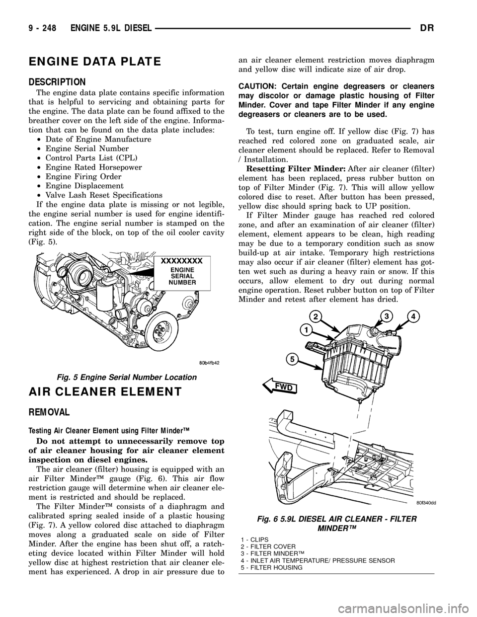
(Fig. 5).
AIR CLEANER ELEMENT
REMOVAL
Testing Air Cleaner Element using Filter MinderŸ
Do not attempt to unnecessarily remove top
of air cleaner housing for air cleaner element
inspection on diesel engines.
The air cleaner (filter) housing is equipped with an
air Filter MinderŸ gauge (Fig. 6). This air flow
restriction gauge will determine when air cleaner ele-
ment is restricted and should be replaced.
The Filter MinderŸ consists of a diaphragm and
calibrated spring sealed inside of a plastic housing
(Fig. 7). A yellow colored disc attached to diaphragm
moves along a graduated scale on side of Filter
Minder. After the engine has been shut off, a ratch-
eting device located within Filter Minder will hold
yellow disc at highest restriction that air cleaner ele-
ment has experienced. A drop in air pressure due toan air cleaner element restriction moves diaphragm
and yellow disc will indicate size of air drop.
CAUTION: Certain engine degreasers or cleaners
may discolor or damage plastic housing of Filter
Minder. Cover and tape Filter Minder if any engine
degreasers or cleaners are to be used.
To test, turn engine off. If yellow disc (Fig. 7) has
reached red colored zone on graduated scale, air
cleaner element should be replaced. Refer to Removal
/ Installation.
Resetting Filter Minder:After air cleaner (filter)
element has been replaced, press rubber button on
top of Filter Minder (Fig. 7). This will allow yellow
colored disc to reset. After button has been pressed,
yellow disc should spring back to UP position.
If Filter Minder gauge has reached red colored
zone, and after an examination of air cleaner (filter)
element, element appears to be clean, high reading
may be due to a temporary condition such as snow
build-up at air intake. Temporary high restrictions
may also occur if air cleaner (filter) element has got-
ten wet such as during a heavy rain or snow. If this
occurs, allow element to dry out during normal
engine operation. Reset rubber button on top of Filter
Minder and retest after element has dried.
Fig. 5 Engine Serial Number Location
Fig. 6 5.9L DIESEL AIR CLEANER - FILTER
MINDERŸ
1 - CLIPS
2 - FILTER COVER
3 - FILTER MINDERŸ
4 - INLET AIR TEMPERATURE/ PRESSURE SENSOR
5 - FILTER HOUSING
9 - 248 ENGINE 5.9L DIESELDR
Page 1478 of 2627
(37) Rotate generator into position. Install upper
bolt and torque upper and lower bolts.
(38)
Install wire harness push-on clip below bracket.
(39) Install wire harness P-clip to top of bracket.
(40) Install fan support and torque to 32 N´m (24
ft. lbs.).
(41) Install cooling fan/drive refer to (Refer to 7 -
COOLING/ENGINE/RADIATOR FAN - INSTALLA-
TION).
(42) Install accessory drive belt (Refer to 7 -
COOLING/ACCESSORY DRIVE/DRIVE BELTS -
INSTALLATION).
(43) Install exhaust manifold/turbocharger assem-
bly, using new gaskets. Start all bolts/spacers by
hand. Torque bolts to 43 N´m (32 ft. lbs.).
(44) Install exhaust manifold heat shield to
exhaust manifold studs. Install retaining nuts.Torque
to 15 N´m (11 ft. lbs.).
(45) Install exhaust bolt retention straps across
cylinders5&6.
(46) Connect turbocharger oil drain tube. Torque
clamp to 8 N´m (71 in. lbs.).
(47) Perform the turbocharger pre-lube procedure.
Refer to Group 11, Exhaust System and Turbo-
charger for the correct procedure.
(48) Connect the turbocharger oil supply line.
Torque to 24 N´m (18 ft. lbs.).
(49) Install air cleaner housing and duct.
(50) Connect air inlet temperature/pressure sensor.
(51) Raise vehicle on hoist.
(52) Install exhaust pipe to turbocharger elbow.
Torque bolts to 11 N´m (100 in. lbs.).
(53) Lower vehicle.
(54) Fill engine coolant (Refer to 7 - COOLING -
STANDARD PROCEDURE).
(55) Start engine and check for leaks.
CYLINDER HEAD COVER(S)
REMOVAL
REMOVALÐCYLINDER HEAD COVER
(1) Disconnect both battery negative cables.
(2) Remove oil fill cap.
(3) Remove the breather cover.
(4) Disconnect the breather hose and breather
drain tube from the breather housing.
(5) Remove cylinder head cover bolts.
(6) Remove the cylinder head cover.
REMOVALÐROCKER HOUSING
(1) Remove cylinder head cover as outlined in this
section.
(2) Disconnect rocker housing injector harness con-
nectors.(3) Remove injector harness nuts from injectors.
(4) Remove rocker housing bolts.
(5) Remove rocker housing and gasket.
CLEANING
Using a suitable solvent, Clean and dry gasket
mating surfaces on cylinder head and rocker housing.
Wipe gasket dry and inspect for re-use.
INSPECTION
The cylinder head cover gasket and rocker hous-
ing gasket, are reusable.However, should cracks,
nicks, or tears be present in the rubber/silicone construc-
tion, the defective components should be replaced. Also
replace gasket if it is no longer flexible. Inspect o-rings
on cylinder head cover bolts.Do not reuse gasket if it
has been removed from the groove in the rocker
housing or cylinder head cover.
INSTALLATION
INSTALLATIONÐCYLINDER HEAD COVER
(1) Inspect cylinder head cover gasket for cuts and
proper installation in groove. Replace if damaged.
(2)
Position cylinder cover on top of rocker housing.
(3) Install bolts.
(4) Starting with the center bolt, torque to 24 N´m
(18 ft. lbs.).
(5) Install breather hose to breather.
(6) Install breather drain hose to breather.
(7) Install breather cover and wire harness clip.
Torque to 24 N´m (18 ft. lbs.).
INSTALLATION - ROCKER HOUSING
(1) Inspect rocker housing gasket for cuts, nicks,
or tears. Replace if damaged or if gasket has come
out of groove.
(2) Inspect rocker housing gasket for proper instal-
lation in groove. Gasket bead must be centered in
groove. A gasket bead that is tilted to the side will
cause an oil leak.
CAUTION: When installing rocker housing onto cyl-
inder head, do not slide housing from side to side,
The gasket could fall out or be damaged.
(3) Install the rocker housing. Carefully guide the
rocker housing evenly down onto the cylinder head.
(4) Install rocker housing bolts and tighten finger
tight.
(5) Torque bolts, working from center out, to 24
Nm (18ft. lbs.).
(6) Install injector harness nuts to injector sole-
noid. Torque to 1.25 Nm (11 in. lbs.).
(7) Connect rocker housing injector harness con-
nections.
DRENGINE 5.9L DIESEL 9 - 255
CYLINDER HEAD (Continued)
Page 1540 of 2627
(9) Remove the turbocharger and gasket from the
exhaust manifold.
(10) If the turbocharger is not to be installed
immediately, cover the opening to prevent material
from entering into the manifold.
(11) If replacing the turbocharger, transfer the tur-
bocharger oil supply fitting to the new assembly.
Tighten fitting to 36 N´m (27 ft. lbs.).
(12) Clean and inspect the sealing surface.
CAUTION: The turbocharger is only serviced as an
assembly. Do not attempt to repair the turbocharger
as turbocharger and/or engine damage can result.
CLEANING
WARNING: To prevent damage or personal injury,
do not use a combustable cleaner to clean the tur-
bocharger.
Clean the turbocharger and exhaust manifold
mounting surfaces with a suitable scraper.
INSPECTION
Visually inspect the turbocharger and exhaust
manifold gasket surfaces. Replace stripped or eroded
mounting studs.
(1) Visually inspect the turbocharger for cracks.
The following cracks are NOT acceptable:
²Cracks in the turbine and compressor housing
that go completely through.
²Cracks in the mounting flange that are longer
than 15 mm (0.6 in.).
²Cracks in the mounting flange that intersect
bolt through-holes.
²Two (2) Cracks in the mounting flange that are
closer than 6.4 mm (0.25 in.) together.
(2) Visually inspect the impeller and compressor
wheel fins for nicks, cracks, or chips. Note: Some
impellers may have a factory placed paint mark
which, after normal operation, appears to be a crack.
Remove this mark with a suitable solvent to verify
that it is not a crack.
(3) Visually inspect the turbocharger compressor
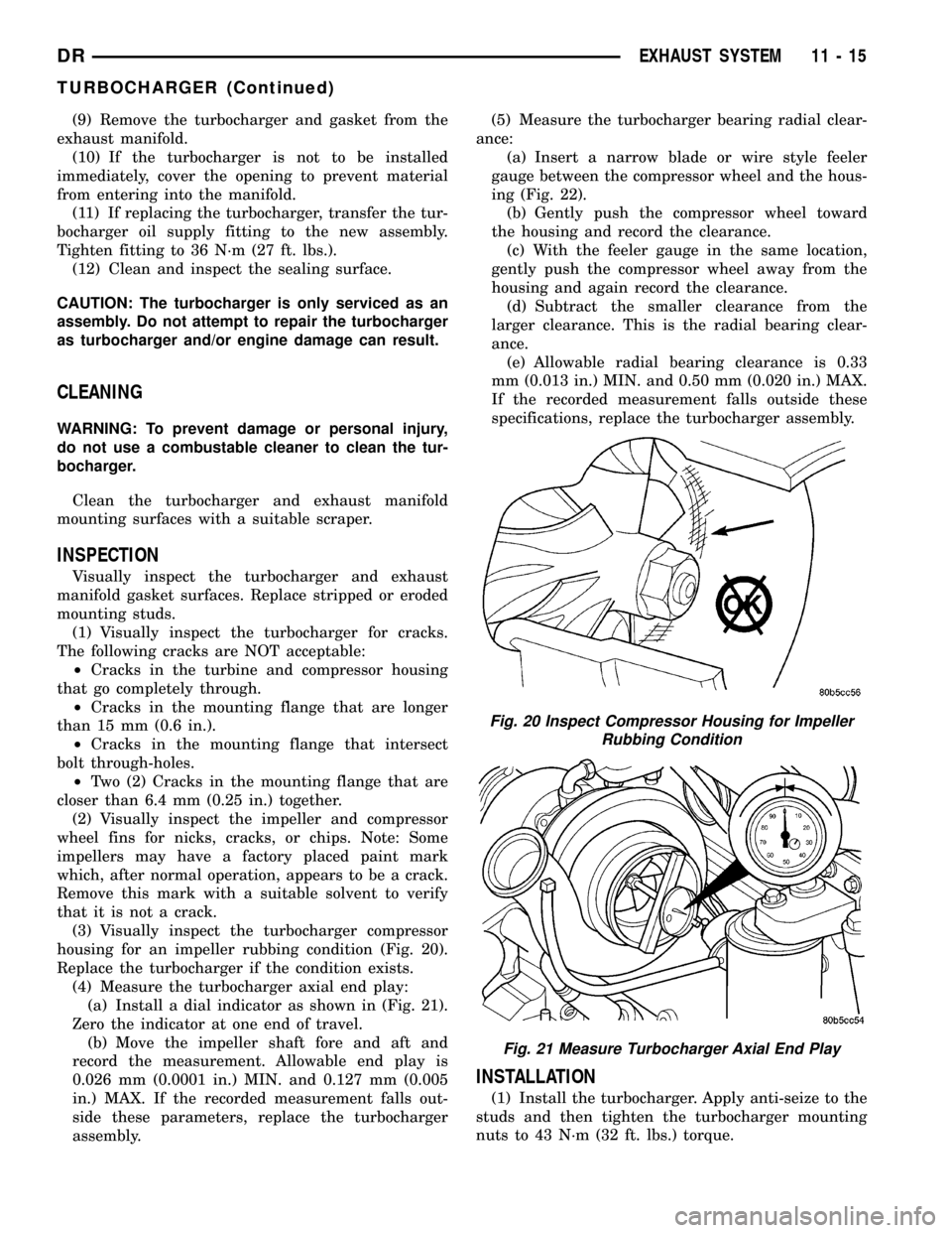
housing for an impeller rubbing condition (Fig. 20).
Replace the turbocharger if the condition exists.
(4) Measure the turbocharger axial end play:
(a) Install a dial indicator as shown in (Fig. 21).
Zero the indicator at one end of travel.
(b) Move the impeller shaft fore and aft and
record the measurement. Allowable end play is
0.026 mm (0.0001 in.) MIN. and 0.127 mm (0.005
in.) MAX. If the recorded measurement falls out-
side these parameters, replace the turbocharger
assembly.(5) Measure the turbocharger bearing radial clear-
ance:
(a) Insert a narrow blade or wire style feeler
gauge between the compressor wheel and the hous-
ing (Fig. 22).
(b) Gently push the compressor wheel toward
the housing and record the clearance.
(c) With the feeler gauge in the same location,
gently push the compressor wheel away from the
housing and again record the clearance.
(d) Subtract the smaller clearance from the
larger clearance. This is the radial bearing clear-
ance.
(e) Allowable radial bearing clearance is 0.33
mm (0.013 in.) MIN. and 0.50 mm (0.020 in.) MAX.
If the recorded measurement falls outside these
specifications, replace the turbocharger assembly.
INSTALLATION
(1) Install the turbocharger. Apply anti-seize to the
studs and then tighten the turbocharger mounting
nuts to 43 N´m (32 ft. lbs.) torque.
Fig. 20 Inspect Compressor Housing for Impeller
Rubbing Condition
Fig. 21 Measure Turbocharger Axial End Play
DREXHAUST SYSTEM 11 - 15
TURBOCHARGER (Continued)
Page 1542 of 2627
CAUTION: Do not apply more than 138 kPa (20 psi)
air pressure to the charge air cooler system, sever
damage to the charge air cooler system may occur.
(3) Connect a regulated air supply to air fitting on
Tool 9022 Adapter. Set air pressure to a Maximum of
138 kPa (20 psi).
(4) Using soapy water check the rubber sleeves,
charge air cooler and intake manifold for leaks.
REMOVAL
WARNING: IF THE ENGINE WAS JUST TURNED
OFF, THE AIR INTAKE SYSTEM TUBES MAY BE
HOT.
(1) Disconnect the battery negative cables.
(2) Discharge the A/C system (Refer to 24 - HEAT-
ING & AIR CONDITIONING/PLUMBING - STAN-
DARD PROCEDURE) and remove the A/C condenser
(Refer to 24 - HEATING & AIR CONDITIONING/
PLUMBING/A/C CONDENSER - REMOVAL) (if A/C
equipped).
(3) Remove the transmission auxiliary cooler
(Refer to 7 - COOLING/TRANSMISSION/TRANS
COOLER - REMOVAL).
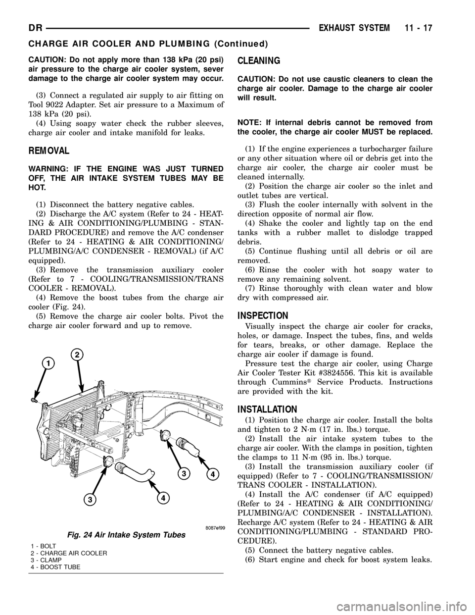
(4) Remove the boost tubes from the charge air
cooler (Fig. 24).
(5) Remove the charge air cooler bolts. Pivot the
charge air cooler forward and up to remove.
CLEANING
CAUTION: Do not use caustic cleaners to clean the
charge air cooler. Damage to the charge air cooler
will result.
NOTE: If internal debris cannot be removed from
the cooler, the charge air cooler MUST be replaced.
(1) If the engine experiences a turbocharger failure
or any other situation where oil or debris get into the
charge air cooler, the charge air cooler must be
cleaned internally.
(2) Position the charge air cooler so the inlet and
outlet tubes are vertical.
(3) Flush the cooler internally with solvent in the
direction opposite of normal air flow.
(4) Shake the cooler and lightly tap on the end
tanks with a rubber mallet to dislodge trapped
debris.
(5) Continue flushing until all debris or oil are
removed.
(6) Rinse the cooler with hot soapy water to
remove any remaining solvent.
(7) Rinse thoroughly with clean water and blow
dry with compressed air.
INSPECTION
Visually inspect the charge air cooler for cracks,
holes, or damage. Inspect the tubes, fins, and welds
for tears, breaks, or other damage. Replace the
charge air cooler if damage is found.
Pressure test the charge air cooler, using Charge
Air Cooler Tester Kit #3824556. This kit is available
through CumminstService Products. Instructions
are provided with the kit.
INSTALLATION
(1) Position the charge air cooler. Install the bolts
and tighten to 2 N´m (17 in. lbs.) torque.
(2) Install the air intake system tubes to the
charge air cooler. With the clamps in position, tighten
the clamps to 11 N´m (95 in. lbs.) torque.
(3) Install the transmission auxiliary cooler (if
equipped) (Refer to 7 - COOLING/TRANSMISSION/
TRANS COOLER - INSTALLATION).
(4) Install the A/C condenser (if A/C equipped)
(Refer to 24 - HEATING & AIR CONDITIONING/
PLUMBING/A/C CONDENSER - INSTALLATION).
Recharge A/C system (Refer to 24 - HEATING & AIR
CONDITIONING/PLUMBING - STANDARD PRO-
CEDURE).
(5) Connect the battery negative cables.
(6) Start engine and check for boost system leaks.
Fig. 24 Air Intake System Tubes
1 - BOLT
2 - CHARGE AIR COOLER
3 - CLAMP
4 - BOOST TUBE
DREXHAUST SYSTEM 11 - 17
CHARGE AIR COOLER AND PLUMBING (Continued)