1998 DODGE RAM 1500 Replace air cleaner
[x] Cancel search: Replace air cleanerPage 1554 of 2627

STANDARD PROCEDURE - HYDROFORM
FENDER RAIL REPAIR
CAUTION: This repair procedure assumes damage
to the right or left hydroform fender rail (Fig. 18).
Prior to any repairs, the vehicle must be mounted
on the appropriate frame repair equipment (ªframe
rackº), checked with three dimensional measuring
equipment, and necessary pull corrections made. If
damage exists in the hydroform fender rail, or cab
beyond the area covered by this service procedure
after dimensional corrections are made, the hydro-
form must be replaced in its entirety. Refer to 23 -
BODY/BODY STRUCTURE/WELD LOCATIONS -
SPECIFICATIONS, when replacing the entire hydro-
form.
(1) Before proceding with this repair procedure
review the required service warnings and precau-
tions. (Refer to 13 - FRAME & BUMPERS/FRAME -
WARNING)
(2) Disconnect and isolate the battery negative
cable.
(3) Remove the front wheelhouse splash shield.
(Refer to 23 - BODY/EXTERIOR/FRONT WHEEL-
HOUSE SPLASH SHIELD - REMOVAL)(4) Remove the fender. (Refer to 23 - BODY/EXTE-
RIOR/FRONT FENDER - REMOVAL)
(5) Remove the A/C condenser, if required. (Refer
to 24 - HEATING & AIR CONDITIONING/PLUMB-
ING/A/C CONDENSER - REMOVAL)
(6) Remove the A/C lines, if required. Refer to the
Heating and Air Conditioning section of the manual
for recommended procedures.
(7) Remove the radiator assembly. (Refer to 7 -
COOLING/ENGINE/RADIATOR - REMOVAL)
(8) Remove the air cleaner and support bracket, if
required. (Refer to 9 - ENGINE/AIR INTAKE SYS-
TEM/AIR CLEANER ELEMENT - REMOVAL)
(9) Remove the integrated power module. (Refer to
8 - ELECTRICAL/POWER DISTRIBUTION/INTE-
GRATED POWER MODULE - REMOVAL)
(10) Remove the bolts and position aside the wire
harness and grounds, if required.
(11) Remove the upper radiator crossmember.
(Refer to 23 - BODY/EXTERIOR/UPPER RADIATOR
CROSSMEMBER - REMOVAL)
(12) Remove the headlamp unit. (Refer to 8 -
ELECTRICAL/LAMPS/LIGHTING - EXTERIOR/
HEADLAMP UNIT - REMOVAL)
(13) Remove the front cab mount to the Front End
Sheet Metal bracket (FESM) bolt.
Fig. 18 HYDROFORM FENDER RAILS
1 - HYDROFORM FENDER RAIL
2 - FRONT END SHEET METAL BRACKET
3 - UPPER RADIATOR CROSSMEMBER BOLTS (4)4 - UPPER RADIATOR CROSSMEMBER
5 - LOWER RADIATOR CROSSMEMBER BOLTS (8)
6 - LOWER RADIATOR CROSSMEMBER
DRFRAMES & BUMPERS 13 - 11
FRAME (Continued)
Page 1555 of 2627

(14) Remove the bolts attaching the lower radiator
crossmember to the hydroform fender rail. (Fig. 18)
CAUTION: Do not use any flame or plasma cutting
equipment to cut the frame in this procedure. The
inaccurate and high temperatures achieved during
flame or plasma cutting will change the metal char-
acteristics and may weaken the frame and/or repair
location.
(15) Using a reciprocating saw or equivalent, cut
the fender rail and shotgun at a straight and square
section of the hydroform and remove.
(16) Smooth and square the cut edges.
(17) Using the damaged structure as a reference
cut the service part at the same location as the first
cut. Smooth and square the cut edges.
NOTE: The repair structure should butt up to the
remaining structure and provide the same overall
vehicle geometry.
(18) Fabricate 51 mm (2.0 in.) long repair inserts
using scrap from the old structure or the replacement
part. It will be necessary to split the inserts on each
of their four sides to fit into the hydroform.
(19) Remove any paint or e-coat from the inserts
and also to the interior and exterior of the hydro-
forms.
(20) Cut plug weld holes as described below.
²On the upper rail, cut one 13 mm (0.5 in.) hole
on each side of the rail, 25 mm (1.0 in.) from the butt
joint of the tubes.
²On the lower rail, cut one 13 mm (0.5 in.) hole
on the top and bottom sides of the rail 25 mm (1.0
in.) from the butt joint of the tube.
²On the lower rail, cut two 13 mm (0.5 in.) holes
on the inner and outer sides of the rail 25 mm (1.0
in.) from the butt joint of the tube.
CAUTION: Shield the surrounding area and compo-
nents from exposure to the welding spatter and
heat.
(21) Install the insert 1º into the replacement part
and tack into place with a weld. (Refer to 13 -
FRAME & BUMPERS/FRAME - SPECIFICATIONS -
WELDING)
(22) Insert the service part into place and using
the appropriate measuring equipment, verify the
front end sheet metal bracket's location in all three
(X,Y, and Z) planes of space. (Fig. 19)
(23) Complete all 360É plug welds.
NOTE: Before the final welding, use three dimen-
sional measuring equipment to ensure the part is in
the correct location. Verify that tap plate extrusion
at the bottom of the vertical post lines up with theisolator and hole in the frame perch mount. Also
ensure the lower radiator closure tube is bolted into
the forward shotgun ends.
(24) Complete welding by making a 360É butt weld
around the fender rails.
(25) Metal finish the exposed welds on the hydro-
forms.
(26) Dress the welded area and apply corrosion
resistant coatings inside and out.
(a) Inside the rail, inject a creeping wax based
rust inhibitor compound to the inside of the hydro-
forms ensuring 100% coverage including the mat-
ing face between the fender rail sections and insert
such that corrosion protection is restored in the
internal cavity.
(b) Apply a durable top coat to the outside of the
repair area.
(27) Install the front cab mount bolt if previously
removed and tighten to 81 N´m (60 ft. lbs.).
(28) Install the lower radiator crossmember bolts
and tighten to 28 N´m (21 ft. lbs.).
(29) Install the headlamp unit. (Refer to 8 - ELEC-
TRICAL/LAMPS/LIGHTING - EXTERIOR/HEAD-
LAMP UNIT - INSTALLATION)
(30) Install the upper radiator crossmember. (Refer
to 23 - BODY/EXTERIOR/UPPER RADIATOR
CROSSMEMBER - INSTALLATION)
(31) Install the wire harness and ground if previ-
ously removed and install the bolts.
(32) Install the integrated power module, if previ-
ously removed. (Refer to 8 - ELECTRICAL/POWER
DISTRIBUTION/INTEGRATED POWER MODULE -
INSTALLATION)
(33) Install the air cleaner bracket and air cleaner,
if previously removed. (Refer to 9 - ENGINE/AIR
INTAKE SYSTEM/AIR CLEANER ELEMENT -
INSTALLATION)
(34) Install the radiator assembly. (Refer to 7 -
COOLING/ENGINE/RADIATOR - INSTALLATION)
(35) Install the A/C lines, if previously removed.
Refer to the Heating and Air Conditioning section of
the manual for the recommended procedures.
(36) Install the A/C condenser, if previously
removed. (Refer to 24 - HEATING & AIR CONDI-
TIONING/PLUMBING/A/C CONDENSER - INSTAL-
LATION)
(37) Install the fender. (Refer to 23 - BODY/EXTE-
RIOR/FRONT FENDER - INSTALLATION)
(38) Install the front wheelhouse splash shield.
(Refer to 23 - BODY/EXTERIOR/FRONT WHEEL-
HOUSE SPLASH SHIELD - INSTALLATION)
(39) Reconnect the battery ground.
13 - 12 FRAMES & BUMPERSDR
FRAME (Continued)
Page 1958 of 2627

(6) Reconnect cable end to attachment stud. Then
with aid of a helper, observe movement of transmis-
sion throttle lever and lever on throttle body.
²If both levers move simultaneously from idle to
half-throttle and back to idle position, adjustment is
correct.
²If transmission throttle lever moves ahead of, or
lags behind throttle body lever, cable adjustment will
be necessary. Or, if throttle body lever prevents
transmission lever from returning to closed position,
cable adjustment will be necessary.
ADJUSTMENT PROCEDURE
(1) Turn ignition switch to OFF position.
(2) Remove air cleaner if necessary.
(3) Disconnect cable end from attachment stud.
Carefully slide cable off stud. Do not pry or pull
cable off.
(4) Verify that transmission throttle lever is in
fully closed position. Then be sure lever on throttle
body is at curb idle position.
(5) Pry the T.V. cable lock (A) into the UP position
(Fig. 226). This will unlock the cable and allow for
readjustment.
(6) Apply just enough tension on the T.V. cable (B)
to remove any slack in the cable.Pulling too tight
will cause the T.V. lever on the transmission to
move out of its idle position, which will result
in an incorrect T.V. cable adjustment.Slide the
sheath of the T.V. cable (D) back and forth until the
centerlines of the T.V. cable end (B) and the throttle
bell crank lever (C) are aligned within one millimeter
(1mm) (Fig. 226).
(7) While holding the T.V. cable in the set position
push the T.V. cable lock (A) into the down position
(Fig. 226). This will lock the present T.V. cable
adjustment.
NOTE: Be sure that as the cable is pulled forward
and centered on the throttle lever stud, the cable
housing moves smoothly with the cable. Due to the
angle at which the cable housing enters the spring
housing, the cable housing may bind slightly and
create an incorrect adjustment.
(8) Reconnect the T.V. cable (B) to the throttle
bellcrank lever (C).
(9) Check cable adjustment. Verify transmission
throttle lever and lever on throttle body move simul-
taneously.
TORQUE CONVERTER
DESCRIPTION
The torque converter (Fig. 227) is a hydraulic
device that couples the engine crankshaft to the
transmission. The torque converter consists of an
outer shell with an internal turbine, a stator, an
overrunning clutch, an impeller and an electronically
applied converter clutch. The converter clutch pro-
vides reduced engine speed and greater fuel economy
when engaged. Clutch engagement also provides
reduced transmission fluid temperatures. The torque
converter hub drives the transmission oil (fluid)
pump.
The torque converter is a sealed, welded unit that
is not repairable and is serviced as an assembly.
CAUTION: The torque converter must be replaced if
a transmission failure resulted in large amounts of
metal or fiber contamination in the fluid. If the fluid
is contaminated, flush the all transmission fluid
cooler(s) and lines.
Fig. 227 Torque Converter Assembly
1 - TURBINE
2 - IMPELLER
3 - HUB
4-STATOR
5 - FRONT COVER
6 - CONVERTER CLUTCH DISC
7 - DRIVE PLATE
DRAUTOMATIC TRANSMISSION - 48RE 21 - 255
THROTTLE VALVE CABLE (Continued)
Page 2129 of 2627

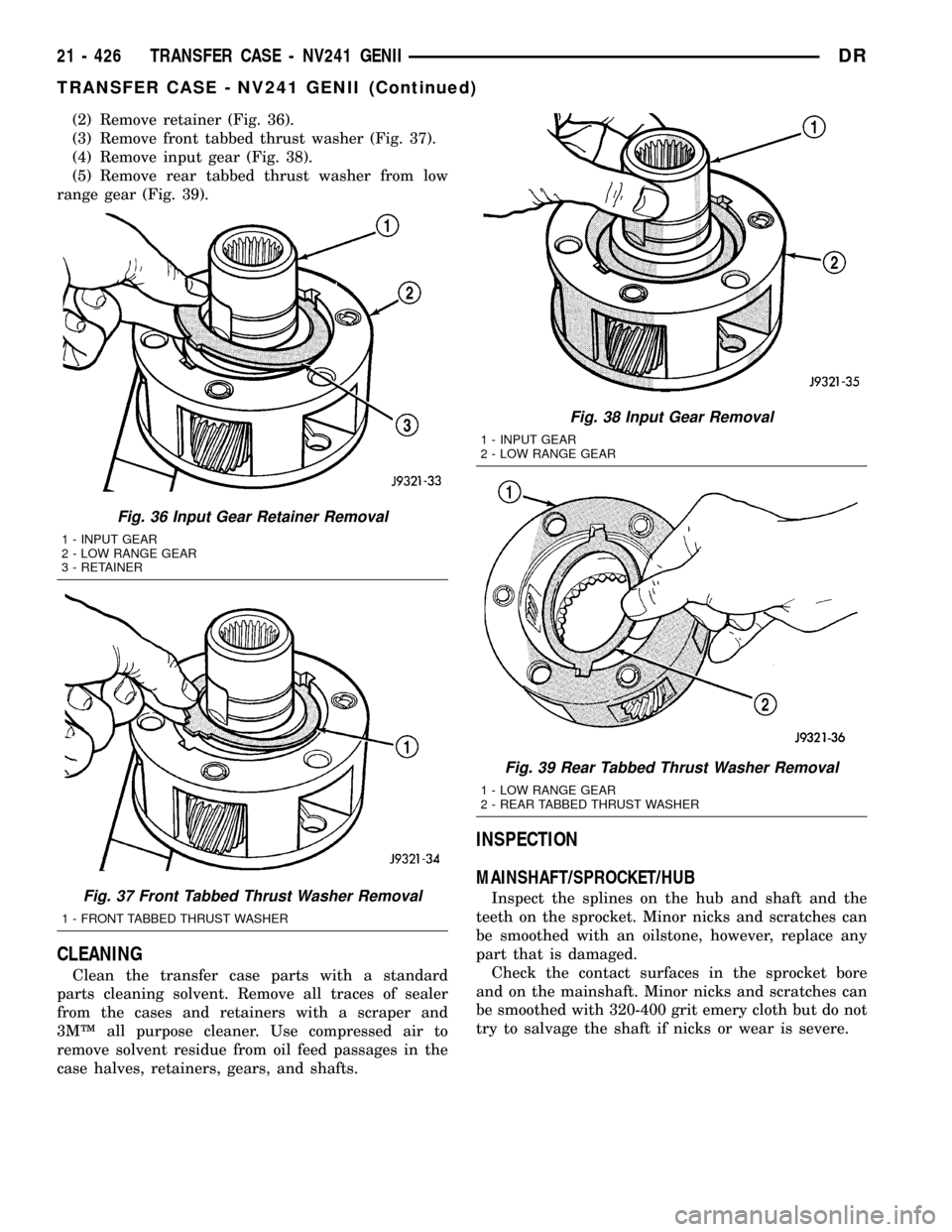
(2) Remove retainer (Fig. 36).
(3) Remove front tabbed thrust washer (Fig. 37).
(4) Remove input gear (Fig. 38).
(5) Remove rear tabbed thrust washer from low
range gear (Fig. 39).
CLEANING
Clean the transfer case parts with a standard
parts cleaning solvent. Remove all traces of sealer
from the cases and retainers with a scraper and
3MŸ all purpose cleaner. Use compressed air to
remove solvent residue from oil feed passages in the
case halves, retainers, gears, and shafts.
INSPECTION
MAINSHAFT/SPROCKET/HUB
Inspect the splines on the hub and shaft and the
teeth on the sprocket. Minor nicks and scratches can
be smoothed with an oilstone, however, replace any
part that is damaged.
Check the contact surfaces in the sprocket bore
and on the mainshaft. Minor nicks and scratches can
be smoothed with 320-400 grit emery cloth but do not
try to salvage the shaft if nicks or wear is severe.
Fig. 36 Input Gear Retainer Removal
1 - INPUT GEAR
2 - LOW RANGE GEAR
3 - RETAINER
Fig. 37 Front Tabbed Thrust Washer Removal
1 - FRONT TABBED THRUST WASHER
Fig. 38 Input Gear Removal
1 - INPUT GEAR
2 - LOW RANGE GEAR
Fig. 39 Rear Tabbed Thrust Washer Removal
1 - LOW RANGE GEAR
2 - REAR TABBED THRUST WASHER
21 - 426 TRANSFER CASE - NV241 GENIIDR
TRANSFER CASE - NV241 GENII (Continued)
Page 2162 of 2627

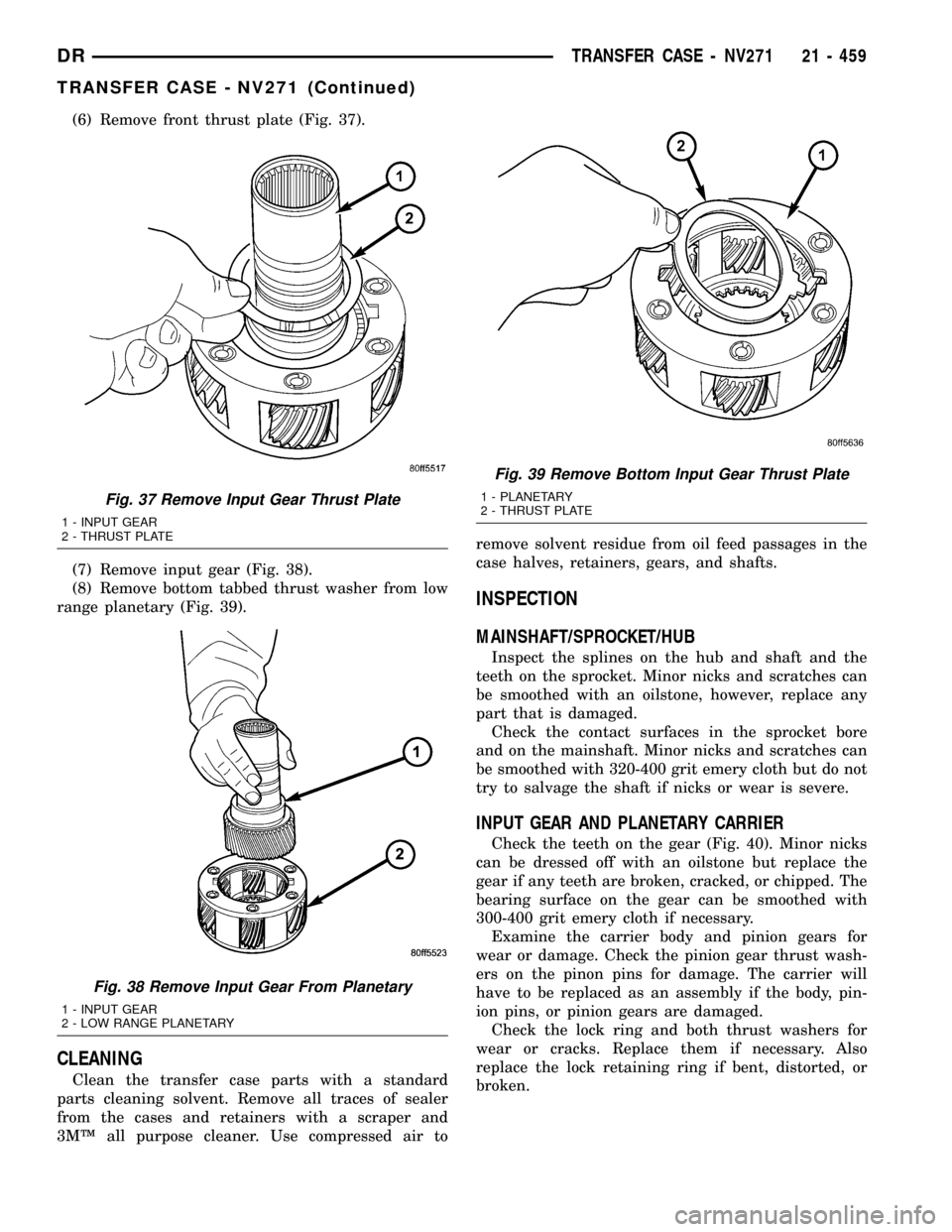
(6) Remove front thrust plate (Fig. 37).
(7) Remove input gear (Fig. 38).
(8) Remove bottom tabbed thrust washer from low
range planetary (Fig. 39).
CLEANING
Clean the transfer case parts with a standard
parts cleaning solvent. Remove all traces of sealer
from the cases and retainers with a scraper and
3MŸ all purpose cleaner. Use compressed air toremove solvent residue from oil feed passages in the
case halves, retainers, gears, and shafts.
INSPECTION
MAINSHAFT/SPROCKET/HUB
Inspect the splines on the hub and shaft and the
teeth on the sprocket. Minor nicks and scratches can
be smoothed with an oilstone, however, replace any
part that is damaged.
Check the contact surfaces in the sprocket bore
and on the mainshaft. Minor nicks and scratches can
be smoothed with 320-400 grit emery cloth but do not
try to salvage the shaft if nicks or wear is severe.
INPUT GEAR AND PLANETARY CARRIER
Check the teeth on the gear (Fig. 40). Minor nicks
can be dressed off with an oilstone but replace the
gear if any teeth are broken, cracked, or chipped. The
bearing surface on the gear can be smoothed with
300-400 grit emery cloth if necessary.
Examine the carrier body and pinion gears for
wear or damage. Check the pinion gear thrust wash-
ers on the pinon pins for damage. The carrier will
have to be replaced as an assembly if the body, pin-
ion pins, or pinion gears are damaged.
Check the lock ring and both thrust washers for
wear or cracks. Replace them if necessary. Also
replace the lock retaining ring if bent, distorted, or
broken.
Fig. 37 Remove Input Gear Thrust Plate
1 - INPUT GEAR
2 - THRUST PLATE
Fig. 38 Remove Input Gear From Planetary
1 - INPUT GEAR
2 - LOW RANGE PLANETARY
Fig. 39 Remove Bottom Input Gear Thrust Plate
1 - PLANETARY
2 - THRUST PLATE
DRTRANSFER CASE - NV271 21 - 459
TRANSFER CASE - NV271 (Continued)
Page 2196 of 2627

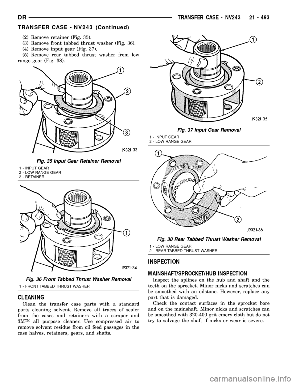
(2) Remove retainer (Fig. 35).
(3) Remove front tabbed thrust washer (Fig. 36).
(4) Remove input gear (Fig. 37).
(5) Remove rear tabbed thrust washer from low
range gear (Fig. 38).
CLEANING
Clean the transfer case parts with a standard
parts cleaning solvent. Remove all traces of sealer
from the cases and retainers with a scraper and
3MŸ all purpose cleaner. Use compressed air to
remove solvent residue from oil feed passages in the
case halves, retainers, gears, and shafts.
INSPECTION
MAINSHAFT/SPROCKET/HUB INSPECTION
Inspect the splines on the hub and shaft and the
teeth on the sprocket. Minor nicks and scratches can
be smoothed with an oilstone. However, replace any
part that is damaged.
Check the contact surfaces in the sprocket bore
and on the mainshaft. Minor nicks and scratches can
be smoothed with 320-400 grit emery cloth but do not
try to salvage the shaft if nicks or wear is severe.
Fig. 35 Input Gear Retainer Removal
1 - INPUT GEAR
2 - LOW RANGE GEAR
3 - RETAINER
Fig. 36 Front Tabbed Thrust Washer Removal
1 - FRONT TABBED THRUST WASHER
Fig. 37 Input Gear Removal
1 - INPUT GEAR
2 - LOW RANGE GEAR
Fig. 38 Rear Tabbed Thrust Washer Removal
1 - LOW RANGE GEAR
2 - REAR TABBED THRUST WASHER
DRTRANSFER CASE - NV243 21 - 493
TRANSFER CASE - NV243 (Continued)
Page 2226 of 2627

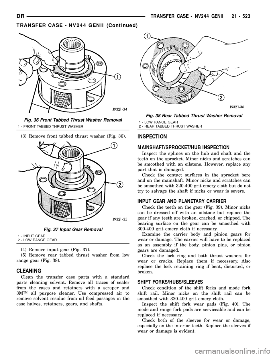
(3) Remove front tabbed thrust washer (Fig. 36).
(4) Remove input gear (Fig. 37).
(5) Remove rear tabbed thrust washer from low
range gear (Fig. 38).
CLEANING
Clean the transfer case parts with a standard
parts cleaning solvent. Remove all traces of sealer
from the cases and retainers with a scraper and
3MŸ all purpose cleaner. Use compressed air to
remove solvent residue from oil feed passages in the
case halves, retainers, gears, and shafts.
INSPECTION
MAINSHAFT/SPROCKET/HUB INSPECTION
Inspect the splines on the hub and shaft and the
teeth on the sprocket. Minor nicks and scratches can
be smoothed with an oilstone. However, replace any
part that is damaged.
Check the contact surfaces in the sprocket bore
and on the mainshaft. Minor nicks and scratches can
be smoothed with 320-400 grit emery cloth but do not
try to salvage the shaft if nicks or wear is severe.
INPUT GEAR AND PLANETARY CARRIER
Check the teeth on the gear (Fig. 39). Minor nicks
can be dressed off with an oilstone but replace the
gear if any teeth are broken, cracked, or chipped. The
bearing surface on the gear can be smoothed with
300-400 grit emery cloth if necessary.
Examine the carrier body and pinion gears for
wear or damage. The carrier will have to be replaced
as an assembly if the body, pinion pins, or pinion
gears are damaged.
Check the lock ring and both thrust washers for
wear or cracks. Replace them if necessary. Also
replace the lock retaining ring if bent, distorted, or
broken.
SHIFT FORKS/HUBS/SLEEVES
Check condition of the shift forks and mode fork
shift rail. Minor nicks on the shift rail can be
smoothed with 320-400 grit emery cloth.
Inspect the shift fork wear pads (Fig. 40). The
mode and range fork pads are serviceable and can be
replaced if necessary.
Check both of the sleeves for wear or damage,
especially on the interior teeth. Replace the sleeves if
wear or damage is evident.
Fig. 36 Front Tabbed Thrust Washer Removal
1 - FRONT TABBED THRUST WASHER
Fig. 37 Input Gear Removal
1 - INPUT GEAR
2 - LOW RANGE GEAR
Fig. 38 Rear Tabbed Thrust Washer Removal
1 - LOW RANGE GEAR
2 - REAR TABBED THRUST WASHER
DRTRANSFER CASE - NV244 GENII 21 - 523
TRANSFER CASE - NV244 GENII (Continued)
Page 2257 of 2627

(8) Remove bottom tabbed thrust washer from low
range planetary (Fig. 38).
CLEANING
Clean the transfer case parts with a standard
parts cleaning solvent. Remove all traces of sealer
from the cases and retainers with a scraper and
3MŸ all purpose cleaner. Use compressed air to
remove solvent residue from oil feed passages in the
case halves, retainers, gears, and shafts.
INSPECTION
MAINSHAFT/SPROCKET/HUB INSPECTION
Inspect the splines on the hub and shaft and the
teeth on the sprocket. Minor nicks and scratches can
be smoothed with an oilstone. However, replace any
part that is damaged.
Check the contact surfaces in the sprocket bore
and on the mainshaft. Minor nicks and scratches can
be smoothed with 320-400 grit emery cloth but do not
try to salvage the shaft if nicks or wear is severe.
INPUT GEAR AND PLANETARY CARRIER
Check the teeth on the gear (Fig. 39). Minor nicks
can be dressed off with an oilstone but replace the
gear if any teeth are broken, cracked, or chipped. The
bearing surface on the gear can be smoothed with
300-400 grit emery cloth if necessary.
Examine the carrier body and pinion gears for
wear or damage. Check the pinion gear thrust wash-
ers on the pinon pins for damage. The carrier will
have to be replaced as an assembly if the body, pin-
ion pins, or pinion gears are damaged.
Check the lock ring and both thrust washers for
wear or cracks. Replace them if necessary. Also
replace the lock retaining ring if bent, distorted, or
broken.
Fig. 39 Input Gear And Carrier Components
1 - PLANETARY CARRIER 4 - CARRIER LOCK RING
2 - REAR THRUST WASHER 5 - CARRIER LOCK RETAINING RING
3 - FRONT THRUST WASHER 6 - INPUT GEAR
Fig. 38 Remove Bottom Input Gear Thrust Plate
1 - PLANETARY
2 - THRUST PLATE
21 - 554 TRANSFER CASE - NV273DR
TRANSFER CASE - NV273 (Continued)