1998 DODGE RAM 1500 tire size
[x] Cancel search: tire sizePage 12 of 2627

VEHICLE CERTIFICATION
LABEL
DESCRIPTION
A vehicle certification label (Fig. 9) is attached to
every DaimlerChrysler Corporation vehicle. The label
certifies that the vehicle conforms to all applicable
Federal Motor Vehicle Standards. The label also lists:
²Month and year of vehicle manufacture.
²Gross Vehicle Weight Rating (GVWR). The gross
front and rear axle weight ratings (GAWR's) are
based on a minimum rim size and maximum cold tire
inflation pressure.
²Vehicle Identification Number (VIN).
²Type of vehicle.
²Type of rear wheels.
²Bar code.
²Month, Day and Hour (MDH) of final assembly.
²Paint and Trim codes.
²Country of origin.The label is located on the driver-side door
shut-face.
Fig. 9 VEHICLE CERTIFICATION LABEL - TYPICAL
DRINTRODUCTION 11
Page 37 of 2627

OPERATION
²CASTERis the forward or rearward tilt of the
steering knuckle from vertical. Tilting the top of the
knuckle forward provides less positive caster. Tilting
the top of the knuckle rearward provides more posi-
tive caster. Positive caster promotes directional sta-
bility. This angle enables the front wheels to return
to a straight ahead position after turns (Fig. 1)
²CAMBERis the inward or outward tilt of the
wheel relative to the center of the vehicle. Tilting the
top of the wheel inward provides negative camber.
Tilting the top of the wheel outward provides positive
camber. Incorrect camber will cause wear on the
inside or outside edge of the tire (Fig. 1)
²TOEis the difference between the leading inside
edges and trailing inside edges of the front tires.
Wheel toe position out of specification cause's unsta-
ble steering, uneven tire wear and steering wheel off-
center. The wheel toe position is thefinalfront
wheel alignment adjustment (Fig. 1)
²THRUST ANGLEis the angle of the rear axle
relative to the centerline of the vehicle. Incorrect
thrust angle can cause off-center steering and exces-sive tire wear. This angle is not adjustable, damaged
component(s) must be replaced to correct the thrust
angle (Fig. 1)
DIAGNOSIS AND TESTING - PRE-ALIGNMENT
INSPECTION
Before starting wheel alignment, the following
inspection and necessary corrections must be com-
pleted. Refer to Suspension and Steering System
Diagnosis Chart below for additional information.
(1) Inspect tires for size, air pressure and tread
wear.
(2) Inspect front wheel bearings for wear.
(3) Inspect front wheels for excessive radial or lat-
eral runout and balance.
(4) Inspect ball studs, linkage pivot points and
steering gear for looseness, roughness or binding.
(5) Inspect suspension components for wear and
noise.
(6) On 4x4 vehicles check suspension height (LD
only).
(7) Road test the vehicle.
SUSPENSION AND STEERING SYSTEM DIAGNOSIS
CONDITION POSSIBLE CAUSES CORRECTION
FRONT END NOISE 1. Loose or worn wheel bearing. 1. Replace wheel bearing.
2. Loose or worn steering or
suspension components.2. Tighten or replace components as
necessary.
3. Loose or worn steering or
suspension components.3. Tighten or replace components as
necessary.
EXCESSIVE PLAY IN
STEERING1. Loose or worn wheel bearing. 1. Replace wheel bearing.
2. Loose or worn steering or
suspension components.2. Tighten or replace components as
necessary.
3. Loose or worn steering gear. 3. Replace steering gear.
FRONT WHEELS SHIMMY 1. Loose or worn wheel bearing. 1. Replace wheel bearing.
2. Loose or worn steering or
suspension components.2. Tighten or replace components as
necessary.
3. Tires worn or out of balance. 3. Replace or balance tires.
4. Alignment. 4. Align vehicle to specifications.
VEHICLE INSTABILITY 1. Loose or worn wheel bearing. 1. Replace wheel bearing.
2. Loose or worn steering or
suspension components.2. Tighten or replace components as
necessary.
3. Tire pressure. 3. Adjust tire pressure.
4. Alignment. 4. Align vehicle to specifications.
2 - 2 WHEEL ALIGNMENTDR
WHEEL ALIGNMENT (Continued)
Page 1273 of 2627
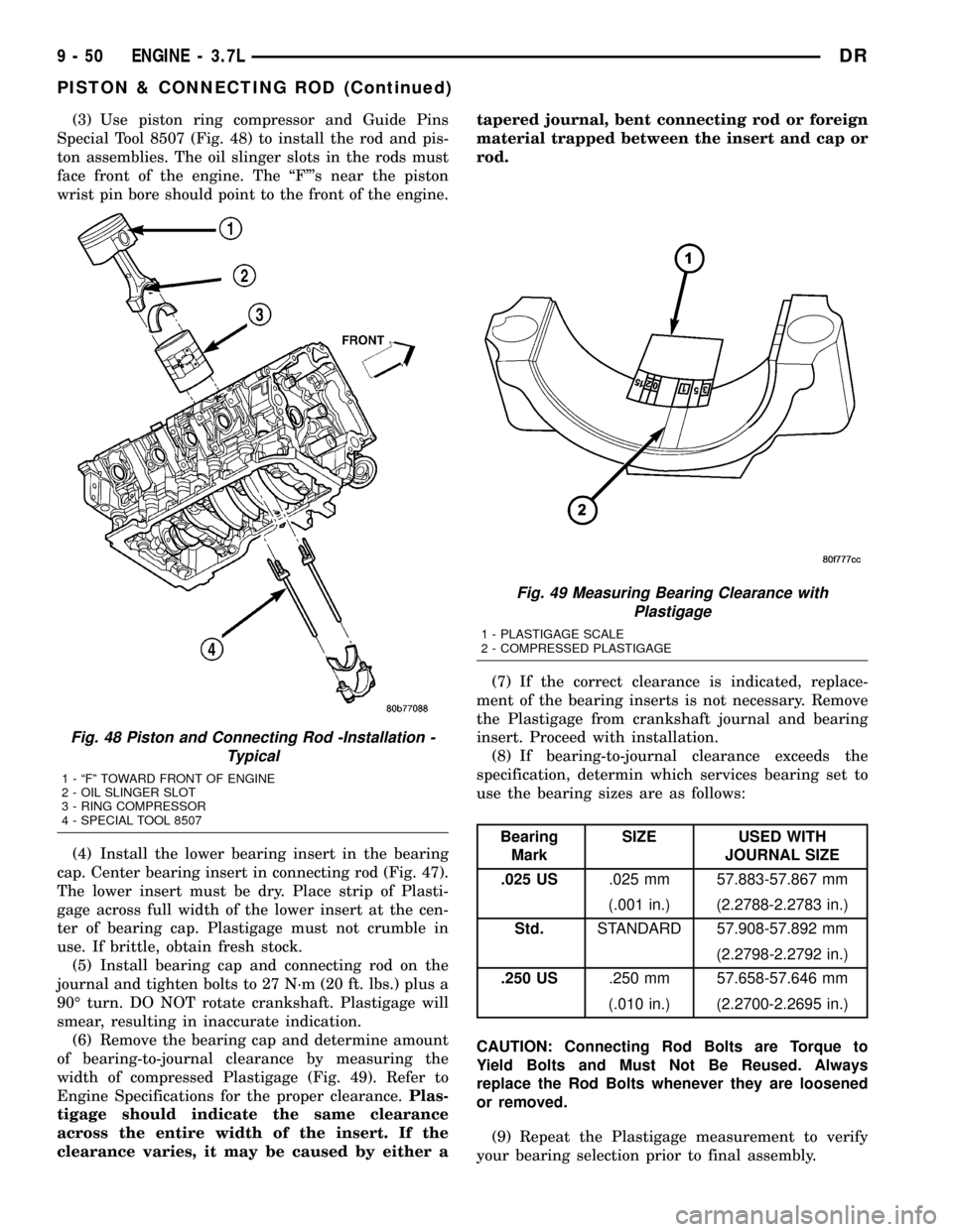
(3) Use piston ring compressor and Guide Pins
Special Tool 8507 (Fig. 48) to install the rod and pis-
ton assemblies. The oil slinger slots in the rods must
face front of the engine. The ªFº's near the piston
wrist pin bore should point to the front of the engine.
(4) Install the lower bearing insert in the bearing
cap. Center bearing insert in connecting rod (Fig. 47).
The lower insert must be dry. Place strip of Plasti-
gage across full width of the lower insert at the cen-
ter of bearing cap. Plastigage must not crumble in
use. If brittle, obtain fresh stock.
(5) Install bearing cap and connecting rod on the
journal and tighten bolts to 27 N´m (20 ft. lbs.) plus a
90É turn. DO NOT rotate crankshaft. Plastigage will
smear, resulting in inaccurate indication.
(6) Remove the bearing cap and determine amount
of bearing-to-journal clearance by measuring the
width of compressed Plastigage (Fig. 49). Refer to
Engine Specifications for the proper clearance.Plas-
tigage should indicate the same clearance
across the entire width of the insert. If the
clearance varies, it may be caused by either atapered journal, bent connecting rod or foreign
material trapped between the insert and cap or
rod.
(7) If the correct clearance is indicated, replace-
ment of the bearing inserts is not necessary. Remove
the Plastigage from crankshaft journal and bearing
insert. Proceed with installation.
(8) If bearing-to-journal clearance exceeds the
specification, determin which services bearing set to
use the bearing sizes are as follows:
Bearing
MarkSIZE USED WITH
JOURNAL SIZE
.025 US.025 mm 57.883-57.867 mm
(.001 in.) (2.2788-2.2783 in.)
Std.STANDARD 57.908-57.892 mm
(2.2798-2.2792 in.)
.250 US.250 mm 57.658-57.646 mm
(.010 in.) (2.2700-2.2695 in.)
CAUTION: Connecting Rod Bolts are Torque to
Yield Bolts and Must Not Be Reused. Always
replace the Rod Bolts whenever they are loosened
or removed.
(9) Repeat the Plastigage measurement to verify
your bearing selection prior to final assembly.
Fig. 48 Piston and Connecting Rod -Installation -
Typical
1 - ªFº TOWARD FRONT OF ENGINE
2 - OIL SLINGER SLOT
3 - RING COMPRESSOR
4 - SPECIAL TOOL 8507
Fig. 49 Measuring Bearing Clearance with
Plastigage
1 - PLASTIGAGE SCALE
2 - COMPRESSED PLASTIGAGE
9 - 50 ENGINE - 3.7LDR
PISTON & CONNECTING ROD (Continued)
Page 1353 of 2627
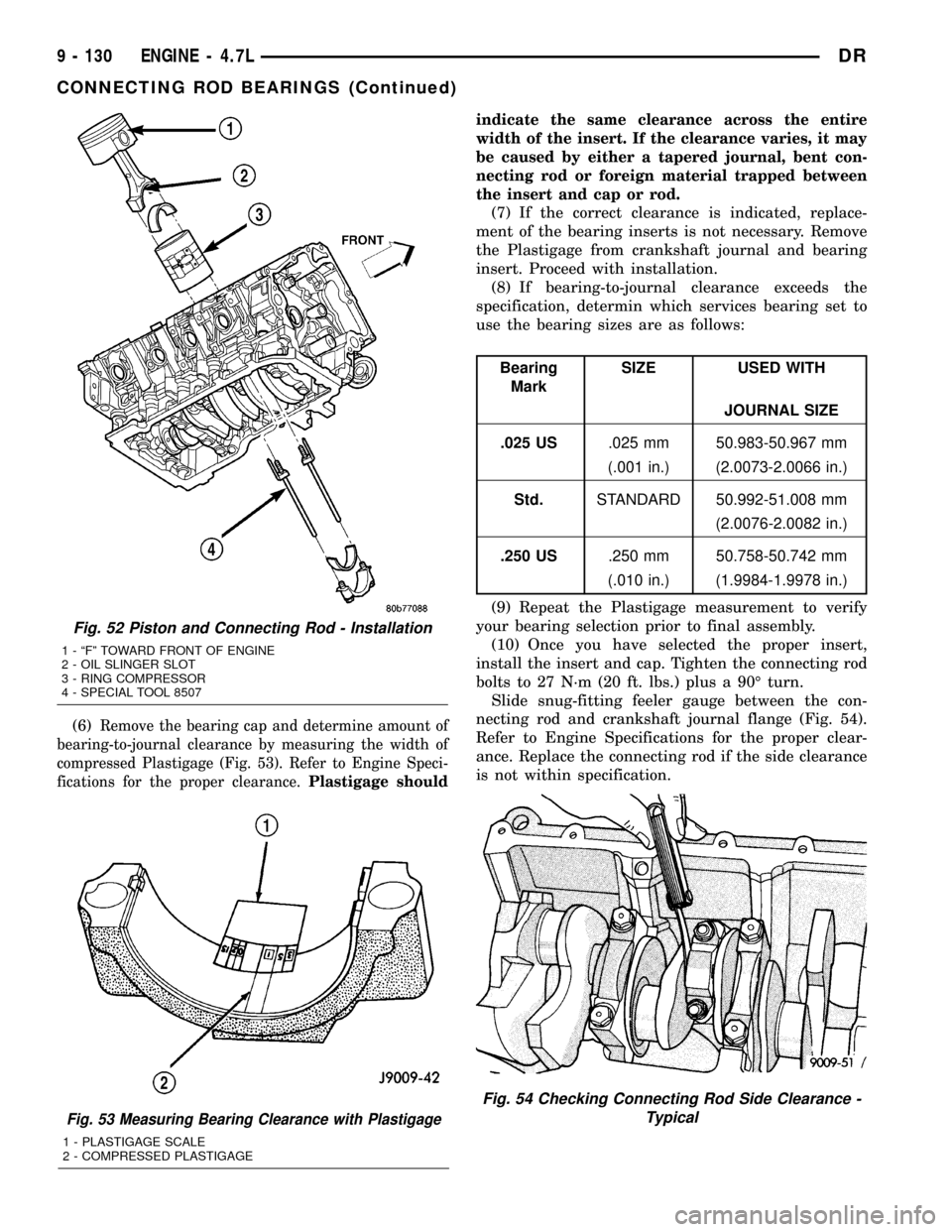
(6)Remove the bearing cap and determine amount of
bearing-to-journal clearance by measuring the width of
compressed Plastigage (Fig. 53). Refer to Engine Speci-
fications for the proper clearance.Plastigage shouldindicate the same clearance across the entire
width of the insert. If the clearance varies, it may
be caused by either a tapered journal, bent con-
necting rod or foreign material trapped between
the insert and cap or rod.
(7) If the correct clearance is indicated, replace-
ment of the bearing inserts is not necessary. Remove
the Plastigage from crankshaft journal and bearing
insert. Proceed with installation.
(8) If bearing-to-journal clearance exceeds the
specification, determin which services bearing set to
use the bearing sizes are as follows:
Bearing
MarkSIZE USED WITH
JOURNAL SIZE
.025 US.025 mm 50.983-50.967 mm
(.001 in.) (2.0073-2.0066 in.)
Std.STANDARD 50.992-51.008 mm
(2.0076-2.0082 in.)
.250 US.250 mm 50.758-50.742 mm
(.010 in.) (1.9984-1.9978 in.)
(9) Repeat the Plastigage measurement to verify
your bearing selection prior to final assembly.
(10) Once you have selected the proper insert,
install the insert and cap. Tighten the connecting rod
bolts to 27 N´m (20 ft. lbs.) plus a 90É turn.
Slide snug-fitting feeler gauge between the con-
necting rod and crankshaft journal flange (Fig. 54).
Refer to Engine Specifications for the proper clear-
ance. Replace the connecting rod if the side clearance
is not within specification.
Fig. 53 Measuring Bearing Clearance with Plastigage
1 - PLASTIGAGE SCALE
2 - COMPRESSED PLASTIGAGE
Fig. 52 Piston and Connecting Rod - Installation
1 - ªFº TOWARD FRONT OF ENGINE
2 - OIL SLINGER SLOT
3 - RING COMPRESSOR
4 - SPECIAL TOOL 8507
Fig. 54 Checking Connecting Rod Side Clearance -
Typical
9 - 130 ENGINE - 4.7LDR
CONNECTING ROD BEARINGS (Continued)
Page 1657 of 2627
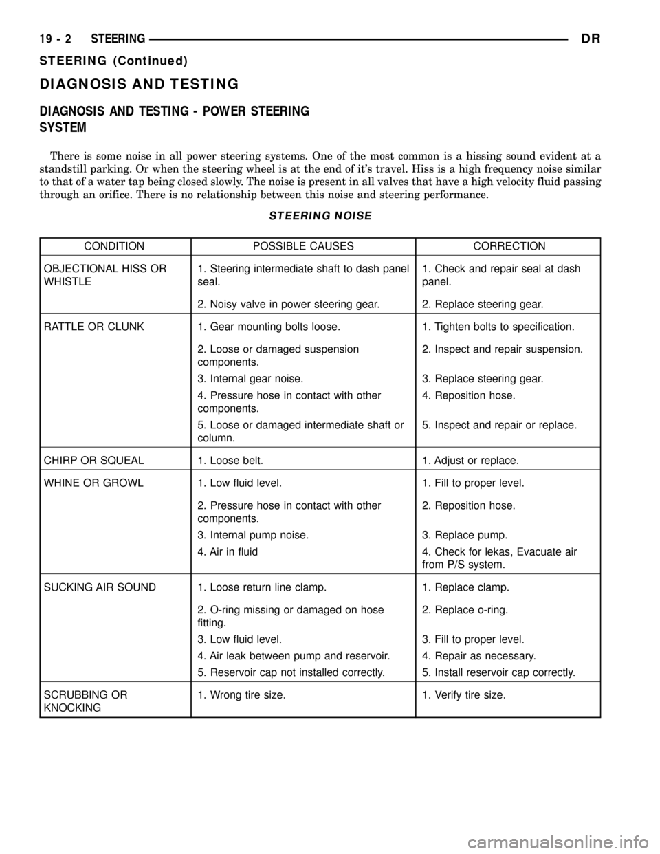
DIAGNOSIS AND TESTING
DIAGNOSIS AND TESTING - POWER STEERING
SYSTEM
There is some noise in all power steering systems. One of the most common is a hissing sound evident at a
standstill parking. Or when the steering wheel is at the end of it's travel. Hiss is a high frequency noise similar
to that of a water tap being closed slowly. The noise is present in all valves that have a high velocity fluid passing
through an orifice. There is no relationship between this noise and steering performance.
STEERING NOISE
CONDITION POSSIBLE CAUSES CORRECTION
OBJECTIONAL HISS OR
WHISTLE1. Steering intermediate shaft to dash panel
seal.1. Check and repair seal at dash
panel.
2. Noisy valve in power steering gear. 2. Replace steering gear.
RATTLE OR CLUNK 1. Gear mounting bolts loose. 1. Tighten bolts to specification.
2. Loose or damaged suspension
components.2. Inspect and repair suspension.
3. Internal gear noise. 3. Replace steering gear.
4. Pressure hose in contact with other
components.4. Reposition hose.
5. Loose or damaged intermediate shaft or
column.5. Inspect and repair or replace.
CHIRP OR SQUEAL 1. Loose belt. 1. Adjust or replace.
WHINE OR GROWL 1. Low fluid level. 1. Fill to proper level.
2. Pressure hose in contact with other
components.2. Reposition hose.
3. Internal pump noise. 3. Replace pump.
4. Air in fluid 4. Check for lekas, Evacuate air
from P/S system.
SUCKING AIR SOUND 1. Loose return line clamp. 1. Replace clamp.
2. O-ring missing or damaged on hose
fitting.2. Replace o-ring.
3. Low fluid level. 3. Fill to proper level.
4. Air leak between pump and reservoir. 4. Repair as necessary.
5. Reservoir cap not installed correctly. 5. Install reservoir cap correctly.
SCRUBBING OR
KNOCKING1. Wrong tire size. 1. Verify tire size.
19 - 2 STEERINGDR
STEERING (Continued)
Page 1861 of 2627
STANDARD PROCEDURE - ALUMINUM
THREAD REPAIR
Damaged or worn threads in the aluminum trans-
mission case and valve body can be repaired by the
use of Heli-CoilsŸ, or equivalent. This repair con-
sists of drilling out the worn-out damaged threads.
Then tap the hole with a special Heli-CoilŸ tap, or
equivalent, and installing a Heli-CoilŸ insert, or
equivalent, into the hole. This brings the hole back to
its original thread size.
Heli-CoilŸ, or equivalent, tools and inserts are
readily available from most automotive parts suppli-
ers.
REMOVAL
NOTE: The overdrive unit can be removed and ser-
viced separately. It is not necessary to remove the
entire transmission assembly to perform overdrive
unit repairs.
(1) Disconnect battery negative cable.
(2) Raise vehicle.
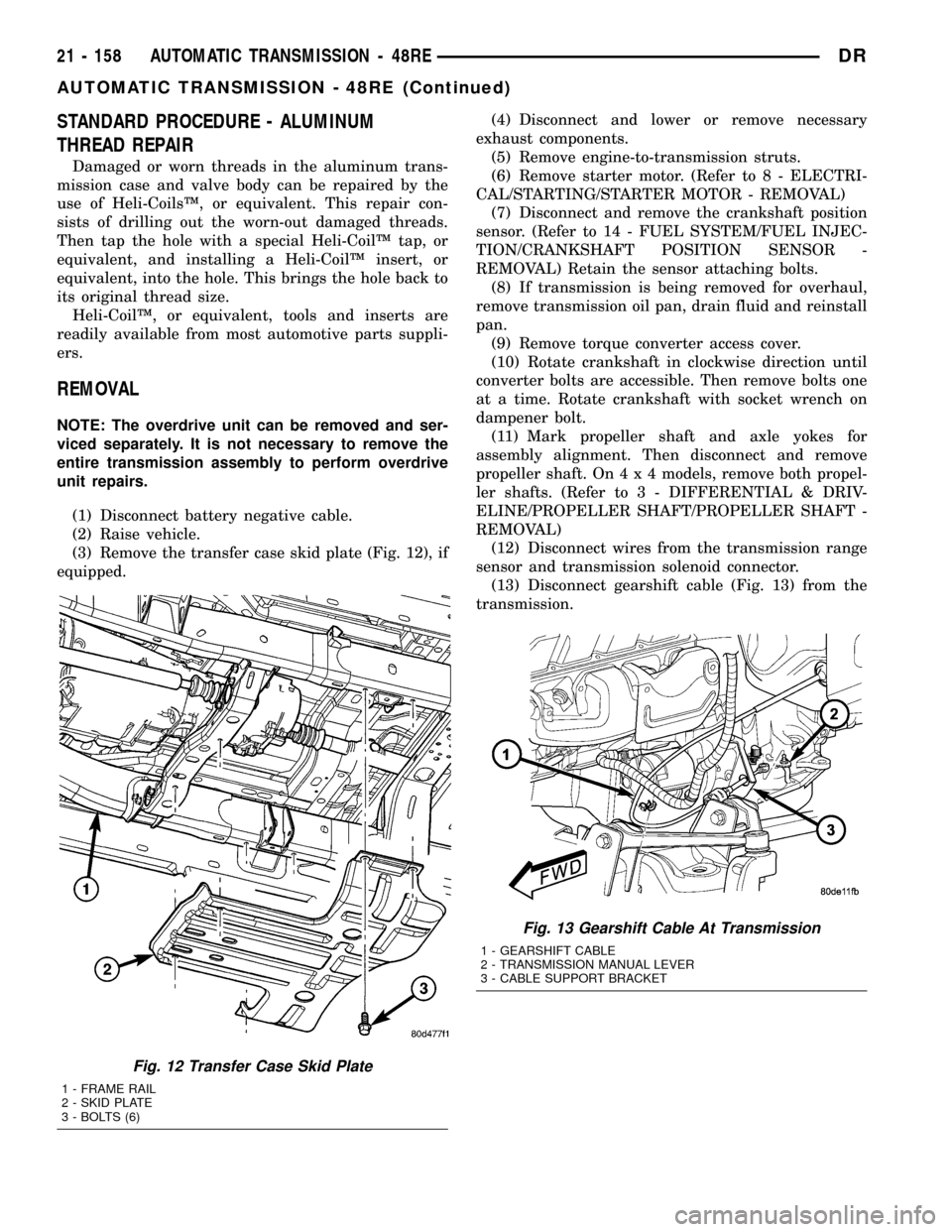
(3) Remove the transfer case skid plate (Fig. 12), if
equipped.(4) Disconnect and lower or remove necessary
exhaust components.
(5) Remove engine-to-transmission struts.
(6) Remove starter motor. (Refer to 8 - ELECTRI-
CAL/STARTING/STARTER MOTOR - REMOVAL)
(7) Disconnect and remove the crankshaft position
sensor. (Refer to 14 - FUEL SYSTEM/FUEL INJEC-
TION/CRANKSHAFT POSITION SENSOR -
REMOVAL) Retain the sensor attaching bolts.
(8) If transmission is being removed for overhaul,
remove transmission oil pan, drain fluid and reinstall
pan.
(9) Remove torque converter access cover.
(10) Rotate crankshaft in clockwise direction until
converter bolts are accessible. Then remove bolts one
at a time. Rotate crankshaft with socket wrench on
dampener bolt.
(11) Mark propeller shaft and axle yokes for
assembly alignment. Then disconnect and remove
propeller shaft. On4x4models, remove both propel-
ler shafts. (Refer to 3 - DIFFERENTIAL & DRIV-
ELINE/PROPELLER SHAFT/PROPELLER SHAFT -
REMOVAL)
(12) Disconnect wires from the transmission range
sensor and transmission solenoid connector.
(13) Disconnect gearshift cable (Fig. 13) from the
transmission.
Fig. 12 Transfer Case Skid Plate
1 - FRAME RAIL
2 - SKID PLATE
3 - BOLTS (6)
Fig. 13 Gearshift Cable At Transmission
1 - GEARSHIFT CABLE
2 - TRANSMISSION MANUAL LEVER
3 - CABLE SUPPORT BRACKET
21 - 158 AUTOMATIC TRANSMISSION - 48REDR
AUTOMATIC TRANSMISSION - 48RE (Continued)
Page 2280 of 2627
TIRES/WHEELS
TABLE OF CONTENTS
page page
TIRES/WHEELS
DIAGNOSIS AND TESTING - TIRE AND
WHEEL RUNOUT......................1
STANDARD PROCEDURE
STANDARD PROCEDURE - TIRE ROTATION . 3
STANDARD PROCEDURE - MATCH
MOUNTING...........................3
STANDARD PROCEDURE - TIRE AND
WHEEL BALANCE......................4
TIRES
DESCRIPTION
DESCRIPTION - SPARE TIRE /
TEMPORARY.........................6
DESCRIPTION - TIRES..................6
DESCRIPTION - RADIAL ± PLY TIRES......6
DESCRIPTION - TIRE PRESSURE FOR
HIGH SPEEDS.........................7
DESCRIPTION - REPLACEMENT TIRES.....7
DESCRIPTION - TIRE INFLATION
PRESSURES..........................7
DIAGNOSIS AND TESTING
DIAGNOSIS AND TESTING - PRESSURE
GAUGES.............................7
DIAGNOSIS AND TESTING - TIRE NOISE
OR VIBRATION........................7
DIAGNOSIS AND TESTING - TREAD WEAR
INDICATORS..........................8
DIAGNOSIS AND TESTING - TIRE WEAR
PATTERNS...........................8
DIAGNOSIS AND TESTING - TIRE/VEHICLE
LEAD................................8STANDARD PROCEDURE - REPAIRING
LEAKS..............................10
SPECIFICATIONS
TIRE REVOLUTIONS PER MILE..........10
WHEELS
DESCRIPTION.........................11
OPERATION...........................11
DIAGNOSIS AND TESTING
WHEEL INSPECTION..................11
STANDARD PROCEDURE
STANDARD PROCEDURE - WHEEL
REPLACEMENT.......................12
STANDARD PROCEDURE - DUAL REAR
WHEEL INSTALLATION.................12
SPECIFICATIONS
TORQUE CHART......................13
STUDS
REMOVAL.............................14
INSTALLATION.........................14
WHEEL COVER
REMOVAL.............................14
INSTALLATION
INSTALLATION - REAR.................14
INSTALLATION - FRONT................14
SPARE TIRE
DESCRIPTION
DESCRIPTION - SPARE / TEMPORARY
TIRE...............................15
DESCRIPTION - FULL SIZE, SPARE WHEEL
WITH MATCHING TIRE.................15
TIRES/WHEELS
DIAGNOSIS AND TESTING - TIRE AND WHEEL
RUNOUT
Radial runout is the difference between the high
and low points on the tire or wheel (Fig. 1).
Lateral runout is thewobbleof the tire or wheel.
Radial runout of more than 1.5 mm (.060 inch)
measured at the center line of the tread may cause
the vehicle to shake.Lateral runout of more than 2.0 mm (.080 inch)
measured near the shoulder of the tire may cause the
vehicle to shake.
Sometimes radial runout can be reduced. Relocate
the wheel and tire assembly on the mounting studs
(See Method 1). If this does not reduce runout to an
acceptable level, the tire can be rotated on the wheel.
(See Method 2).
DRTIRES/WHEELS 22 - 1
Page 2285 of 2627

TIRES
DESCRIPTION
DESCRIPTION - SPARE TIRE / TEMPORARY
The temporary spare tire is designed for emer-
gency use only. The original tire should be repaired
or replaced at the first opportunity, then reinstalled.
Do not exceed speeds of 50 M.P.H. when using the
temporary spare tire. Refer to Owner's Manual for
complete details.
DESCRIPTION - TIRES
Tires are designed and engineered for each specific
vehicle. They provide the best overall performance
for normal operation. The ride and handling charac-
teristics match the vehicle's requirements. With
proper care they will give excellent reliability, trac-
tion, skid resistance, and tread life.
Driving habits have more effect on tire life than
any other factor. Careful drivers will obtain in most
cases, much greater mileage than severe use or care-
less drivers. A few of the driving habits which will
shorten the life of any tire are:
²Rapid acceleration
²Severe brake applications
²High speed driving
²Excessive speeds on turns
²Striking curbs and other obstacles
Radial-ply tires are more prone to irregular tread
wear. It is important to follow the tire rotation inter-
val shown in the section on Tire Rotation, (Refer to
22 - TIRES/WHEELS - STANDARD PROCEDURE).
This will help to achieve a greater tread life.
TIRE IDENTIFICATION
Tire type, size, aspect ratio and speed rating are
encoded in the letters and numbers imprinted on the
side wall of the tire. Refer to the chart to decipher
the tire identification code (Fig. 11).
Performance tires have a speed rating letter after
the aspect ratio number. The speed rating is not
always printed on the tire sidewall. These ratings
are:
²Qup to 100 mph
²Rup to 106 mph
²Sup to 112 mph
²Tup to 118 mph
²Uup to 124 mph
²Hup to 130 mph
²Vup to 149 mph
²Zmore than 149 mph (consult the tire manu-
facturer for the specific speed rating)An All Season type tire will have eitherM+S,M
&SorM±S(indicating mud and snow traction)
imprinted on the side wall.
TIRE CHAINS
Tire snow chains may be used oncertainmodels.
Refer to the Owner's Manual for more information.
DESCRIPTION - RADIAL ± PLY TIRES
Radial-ply tires improve handling, tread life and
ride quality, and decrease rolling resistance.
Radial-ply tires must always be used in sets of
four. Under no circumstances should they be used on
the front only. They may be mixed with temporary
spare tires when necessary. A maximum speed of 50
MPH is recommended while a temporary spare is in
use.
Radial-ply tires have the same load-carrying capac-
ity as other types of tires of the same size. They also
use the same recommended inflation pressures.
The use of oversized tires, either in the front or
rear of the vehicle, can cause vehicle drive train fail-
ure. This could also cause inaccurate wheel speed
signals when the vehicle is equipped with Anti-Lock
Brakes.
The use of tires from different manufactures on the
same vehicle is NOT recommended. The proper tire
pressure should be maintained on all four tires.
Fig. 11 Tire Identification
22 - 6 TIRES/WHEELSDR