1998 DODGE RAM 1500 service
[x] Cancel search: servicePage 1484 of 2627
(g) Release the spring tension and remove the
compressor. Verify that the collets are seated by
tapping on the valve stem with a plastic hammer.
(12) Using the crankshaft barring tool, rotate the
engine until the next crankshaft damper paint mark
aligns with the mark you placed on the cover.In this
position, cylinders #2 and #5 can be serviced.
(13) Repeat the valve spring compressing proce-
dure previously performed and service the retainers,
springs, and seals as necessary.
(14) Using the crankshaft barring tool, rotate the
engine until the next crankshaft damper paint mark
aligns with the mark you placed on the cover.In this
position, cylinders #3 and #4 can be serviced.
(15) Repeat the spring compressing procedure pre-
viously performed and service the retainers, springs,
and seals as necessary.
INSTALLATION
(1) Install rocker housing.
(2) Install fuel injectors and high pressure fuel
lines.
(3) Lubricate the valve tips and install the cross-
heads in their original locations.
(4) Lubricate the crossheads and push rod sockets
and install the rocker arms and pedestals in their
original locations. Tighten bolts to 36 N´m (27 ft. lbs.)
torque.
(5)Verify valve lash adjustment (Refer to 9 -
ENGINE/CYLINDER HEAD/INTAKE/EXHAUST
VALVES & SEATS - STANDARD PROCEDURE).
(6) Install cylinder head cover and reusable gasket
(Refer to 9 - ENGINE/CYLINDER HEAD/CYLIN-
DER HEAD COVER(S) - INSTALLATION).
(7) Connect battery negative cables.
ROCKER ARM / ADJUSTER
ASSY
DESCRIPTION
The unique intake and exhaust rocker arms have
their own rocker shafts and are lubricated by pas-
sages intersecting the cylinder block main oil rifle.
Crossheads are used, which allow each rocker arm to
operate two valves.
The solid push rods are hardened at the rocker
arm and tappet contact areas for superior strength
and durability.
REMOVAL
(1) Disconnect the battery negative cables.
(2) Remove cylinder head cover (Refer to 9 -
ENGINE/CYLINDER HEAD/CYLINDER HEAD
COVER(S) - REMOVAL).
(3) Remove the rocker arm/pedestal fasteners (Fig.
36) and remove rocker arm and pedestal from cylin-
der head. Mark the arms and pedestals so they can
be installed in their original position.
CAUTION: When removing the rocker arms, the
sockets (Fig. 37) may come loose and fall into the
engine. Make sure they stay with the arm upon
removal/installation.
(4) Lift the push rod(s) up and out of the engine
(Fig. 38). Mark them so they can be installed in their
original position.
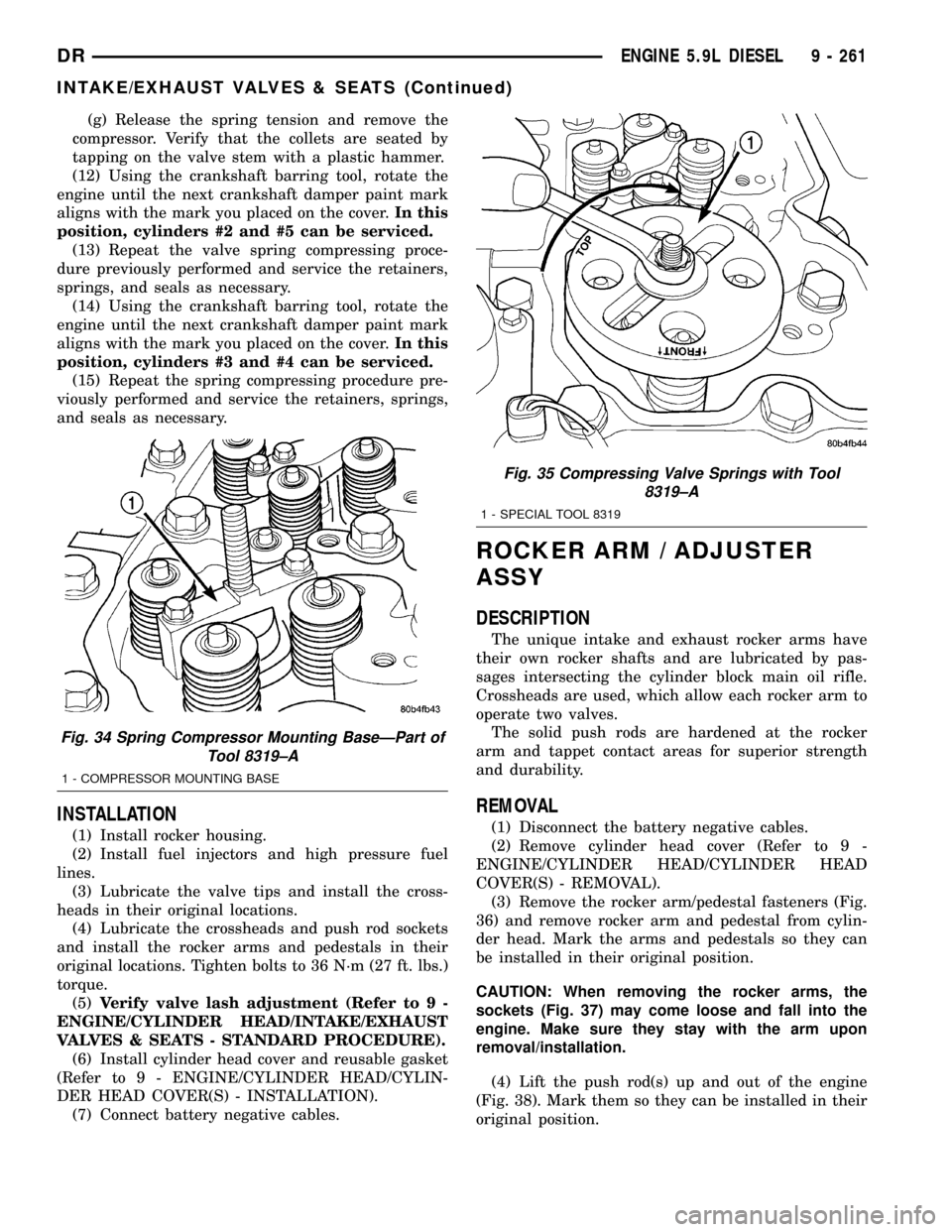
Fig. 34 Spring Compressor Mounting BaseÐPart of
Tool 8319±A
1 - COMPRESSOR MOUNTING BASE
Fig. 35 Compressing Valve Springs with Tool
8319±A
1 - SPECIAL TOOL 8319
DRENGINE 5.9L DIESEL 9 - 261
INTAKE/EXHAUST VALVES & SEATS (Continued)
Page 1491 of 2627
Inspect the cylinder bores for damage or excessive
wear.
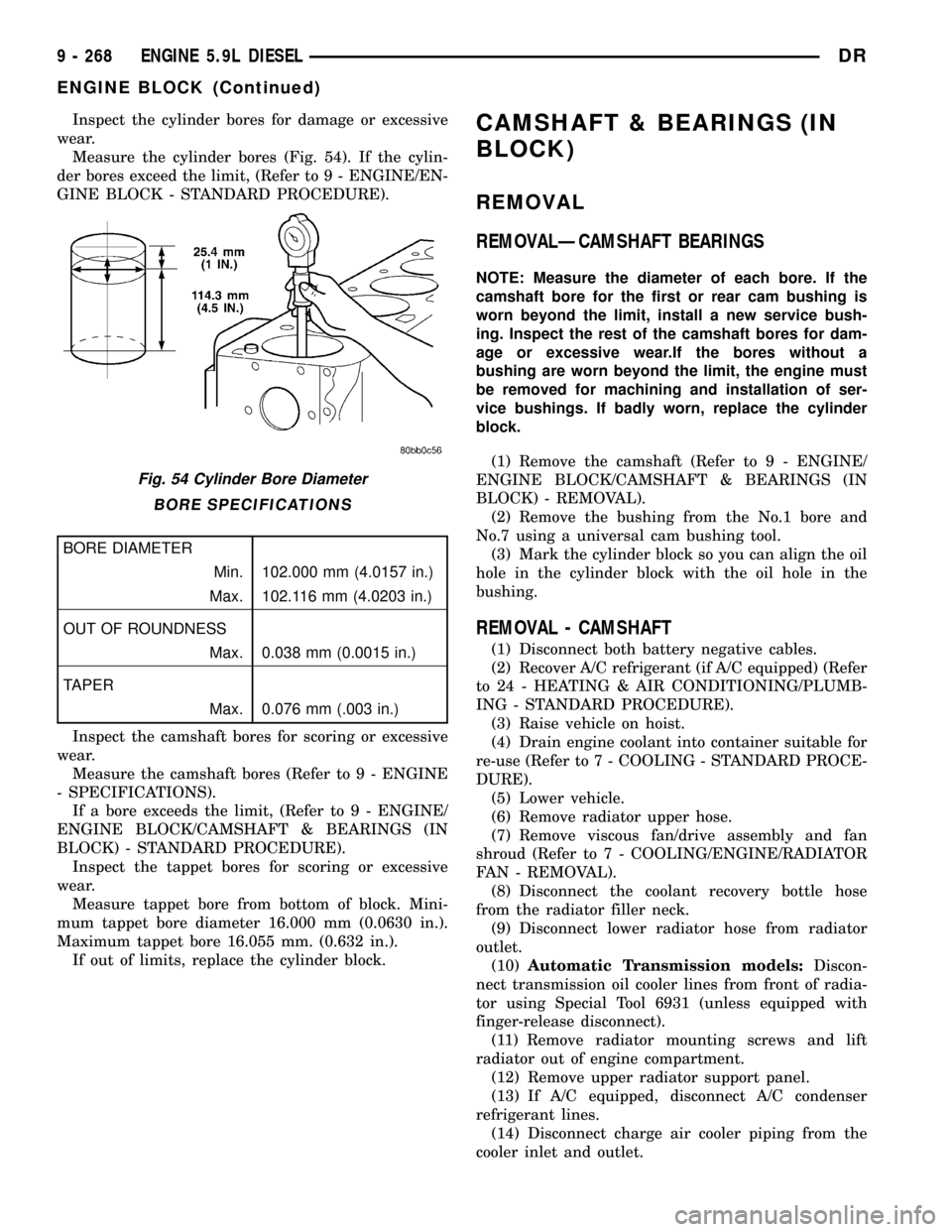
Measure the cylinder bores (Fig. 54). If the cylin-
der bores exceed the limit, (Refer to 9 - ENGINE/EN-
GINE BLOCK - STANDARD PROCEDURE).
BORE SPECIFICATIONS
BORE DIAMETER
Min. 102.000 mm (4.0157 in.)
Max. 102.116 mm (4.0203 in.)
OUT OF ROUNDNESS
Max. 0.038 mm (0.0015 in.)
TAPER
Max. 0.076 mm (.003 in.)
Inspect the camshaft bores for scoring or excessive
wear.
Measure the camshaft bores (Refer to 9 - ENGINE
- SPECIFICATIONS).
If a bore exceeds the limit, (Refer to 9 - ENGINE/
ENGINE BLOCK/CAMSHAFT & BEARINGS (IN
BLOCK) - STANDARD PROCEDURE).
Inspect the tappet bores for scoring or excessive
wear.
Measure tappet bore from bottom of block. Mini-
mum tappet bore diameter 16.000 mm (0.0630 in.).
Maximum tappet bore 16.055 mm. (0.632 in.).
If out of limits, replace the cylinder block.
CAMSHAFT & BEARINGS (IN
BLOCK)
REMOVAL
REMOVALÐCAMSHAFT BEARINGS
NOTE: Measure the diameter of each bore. If the
camshaft bore for the first or rear cam bushing is
worn beyond the limit, install a new service bush-
ing. Inspect the rest of the camshaft bores for dam-
age or excessive wear.If the bores without a
bushing are worn beyond the limit, the engine must
be removed for machining and installation of ser-
vice bushings. If badly worn, replace the cylinder
block.
(1) Remove the camshaft (Refer to 9 - ENGINE/
ENGINE BLOCK/CAMSHAFT & BEARINGS (IN
BLOCK) - REMOVAL).
(2) Remove the bushing from the No.1 bore and
No.7 using a universal cam bushing tool.
(3) Mark the cylinder block so you can align the oil
hole in the cylinder block with the oil hole in the
bushing.
REMOVAL - CAMSHAFT
(1) Disconnect both battery negative cables.
(2) Recover A/C refrigerant (if A/C equipped) (Refer
to 24 - HEATING & AIR CONDITIONING/PLUMB-
ING - STANDARD PROCEDURE).
(3) Raise vehicle on hoist.
(4) Drain engine coolant into container suitable for
re-use (Refer to 7 - COOLING - STANDARD PROCE-
DURE).
(5) Lower vehicle.
(6) Remove radiator upper hose.
(7) Remove viscous fan/drive assembly and fan
shroud (Refer to 7 - COOLING/ENGINE/RADIATOR
FAN - REMOVAL).
(8) Disconnect the coolant recovery bottle hose
from the radiator filler neck.
(9) Disconnect lower radiator hose from radiator
outlet.
(10)Automatic Transmission models:Discon-
nect transmission oil cooler lines from front of radia-
tor using Special Tool 6931 (unless equipped with
finger-release disconnect).
(11) Remove radiator mounting screws and lift
radiator out of engine compartment.
(12) Remove upper radiator support panel.
(13) If A/C equipped, disconnect A/C condenser
refrigerant lines.
(14) Disconnect charge air cooler piping from the
cooler inlet and outlet.
Fig. 54 Cylinder Bore Diameter
9 - 268 ENGINE 5.9L DIESELDR
ENGINE BLOCK (Continued)
Page 1500 of 2627
(7) Install the flywheel or converter drive plate.
Tighten the bolts to 137 N´m (101 ft. lbs.) torque.
(8) Install the clutch cover and disc (if equipped)
(Refer to 6 - CLUTCH/CLUTCH DISC - INSTALLA-
TION).
(9) Install the transmission and transfer case (if
equipped).
(10) Lower vehicle.
(11) Connect battery negative cables.
(12) Check engine oil level and adjust, if necessary.
(13) Start engine and check for oil leaks.
CRANKSHAFT REAR OIL SEAL
RETAINER
REMOVAL
(1) Disconnect the battery negative cables.
(2) Raise vehicle on hoist.
(3) Remove the oil pan drain plug and drain the
engine oil. Re-install plug and torque to 50 N´m (44
ft. lbs.) torque.
(4) Remove transmission and transfer case (if
equipped) from vehicle.
(5)
Remove flywheel or torque converter drive plate.
(6) Disconnect starter cables from starter motor.
(7) Remove starter motor (Refer to 8 - ELECTRI-
CAL/STARTING/STARTER MOTOR - REMOVAL)
and transmission adapter plate assembly.
(8) Remove four (4) oil pan rear bolts. Slide a
feeler gauge between the seal retainer and oil pan
gasket to break the seal.(9) Remove the six (6) retainer-to-block bolts (Fig.
73).
(10) Remove the rear seal retainer and gasket
(Fig. 73).
(11) Support the seal retainer and drive out the
crankshaft seal with a hammer and suitable punch.
INSTALLATION
(1) If using the old seal retainer, the crankshaft
seal must be replaced.
(2) Inspect oil pan gasket for nickes or cuts. If gas-
ket is damaged, the oil pan must be removed and
gasket must be replaced. Wipe oil pan gasket dry and
apply light coating of RTV.
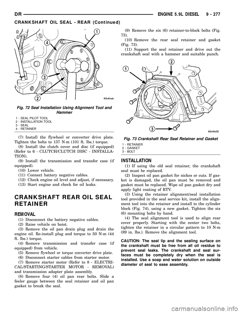
(3) Using the retainer alignment/seal installation
tool provided in the seal service kit, install the align-
ment tool into the retainer and install to the cylinder
block (Fig. 74), using a new gasket. Tighten the six
(6) mounting bolts by hand.
(4) The seal alignment tool is used to align rear
cover properly. Starting with the center two bolts,
tighten the retainer in a circular pattern to 10 N´m
(89 in. lbs.). Remove the alignment tool.
CAUTION: The seal lip and the sealing surface on
the crankshaft must be free from all oil residue to
prevent seal leaks. The crankshaft and seal sur-
faces must be completely dry when the seal is
installed. Use a soap and water solution on outside
diameter of seal to ease assembly.
Fig. 72 Seal Installation Using Alignment Tool and
Hammer
1 - SEAL PILOT TOOL
2 - INSTALLATION TOOL
3 - SEAL
4 - RETAINER
Fig. 73 Crankshaft Rear Seal Retainer and Gasket
1 - RETAINER
2 - GASKET
3 - BOLT
DRENGINE 5.9L DIESEL 9 - 277
CRANKSHAFT OIL SEAL - REAR (Continued)
Page 1515 of 2627
OIL
STANDARD PROCEDURE
STANDARD PROCEDURE - ENGINE OIL LEVEL
CAUTION: Do not overfill crankcase with engine oil,
oil foaming and oil pressure loss can result.
To ensure proper lubrication of an engine, the
engine oil must be maintained at an acceptable level.
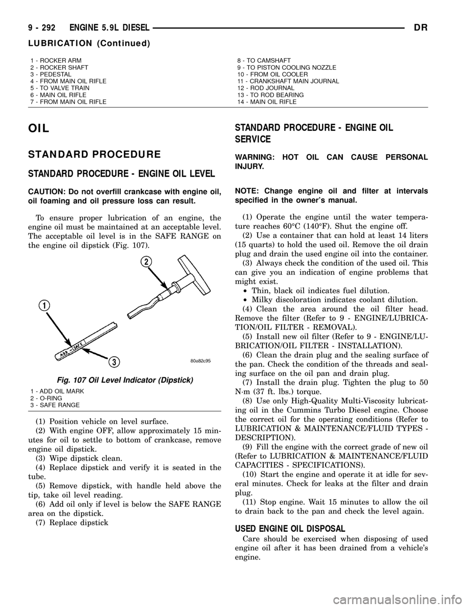
The acceptable oil level is in the SAFE RANGE on
the engine oil dipstick (Fig. 107).
(1) Position vehicle on level surface.
(2) With engine OFF, allow approximately 15 min-
utes for oil to settle to bottom of crankcase, remove
engine oil dipstick.
(3) Wipe dipstick clean.
(4) Replace dipstick and verify it is seated in the
tube.
(5) Remove dipstick, with handle held above the
tip, take oil level reading.
(6) Add oil only if level is below the SAFE RANGE
area on the dipstick.
(7) Replace dipstick
STANDARD PROCEDURE - ENGINE OIL
SERVICE
WARNING: HOT OIL CAN CAUSE PERSONAL
INJURY.
NOTE: Change engine oil and filter at intervals
specified in the owner's manual.
(1) Operate the engine until the water tempera-
ture reaches 60ÉC (140ÉF). Shut the engine off.
(2) Use a container that can hold at least 14 liters
(15 quarts) to hold the used oil. Remove the oil drain
plug and drain the used engine oil into the container.
(3) Always check the condition of the used oil. This
can give you an indication of engine problems that
might exist.
²Thin, black oil indicates fuel dilution.
²Milky discoloration indicates coolant dilution.
(4) Clean the area around the oil filter head.
Remove the filter (Refer to 9 - ENGINE/LUBRICA-
TION/OIL FILTER - REMOVAL).
(5) Install new oil filter (Refer to 9 - ENGINE/LU-
BRICATION/OIL FILTER - INSTALLATION).
(6) Clean the drain plug and the sealing surface of
the pan. Check the condition of the threads and seal-
ing surface on the oil pan and drain plug.
(7) Install the drain plug. Tighten the plug to 50
N´m (37 ft. lbs.) torque.
(8) Use only High-Quality Multi-Viscosity lubricat-
ing oil in the Cummins Turbo Diesel engine. Choose
the correct oil for the operating conditions (Refer to
LUBRICATION & MAINTENANCE/FLUID TYPES -
DESCRIPTION).
(9) Fill the engine with the correct grade of new oil
(Refer to LUBRICATION & MAINTENANCE/FLUID
CAPACITIES - SPECIFICATIONS).
(10) Start the engine and operate it at idle for sev-
eral minutes. Check for leaks at the filter and drain
plug.
(11) Stop engine. Wait 15 minutes to allow the oil
to drain back to the pan and check the level again.
USED ENGINE OIL DISPOSAL
Care should be exercised when disposing of used
engine oil after it has been drained from a vehicle's
engine.
1 - ROCKER ARM
2 - ROCKER SHAFT
3 - PEDESTAL
4 - FROM MAIN OIL RIFLE
5 - TO VALVE TRAIN
6 - MAIN OIL RIFLE
7 - FROM MAIN OIL RIFLE8 - TO CAMSHAFT
9 - TO PISTON COOLING NOZZLE
10 - FROM OIL COOLER
11 - CRANKSHAFT MAIN JOURNAL
12 - ROD JOURNAL
13 - TO ROD BEARING
14 - MAIN OIL RIFLE
Fig. 107 Oil Level Indicator (Dipstick)
1 - ADD OIL MARK
2 - O-RING
3 - SAFE RANGE
9 - 292 ENGINE 5.9L DIESELDR
LUBRICATION (Continued)
Page 1524 of 2627
(23) Install the windshield washer reservoir to the
fan shroud and connect the washer pump supply
hose and electrical connection.
(24) Install the coolant recovery bottle to the fan
shroud and connect the hose to the radiator filler
neck.
(25) Install the radiator upper hose and clamps.
(26) Add engine oil.
(27) Add coolant (Refer to 7 - COOLING - STAN-
DARD PROCEDURE).
(28) Connect the battery cables.
(29) Start engine and inspect for leaks.
GEAR HOUSING COVER
REMOVAL
(1) Disconnect both battery negative cables.
(2) Raise vehicle on hoist.
(3) Partially drain engine coolant into container
suitable for re-use (Refer to 7 - COOLING - STAN-
DARD PROCEDURE).
(4) Lower vehicle.
(5) Remove radiator upper hose.
(6) Disconnect coolant recovery bottle hose from
radiator filler neck and lift bottle off of fan shroud.
(7) Disconnect windshield washer pump supply
hose and electrical connections and lift washer bottle
off of fan shroud.
(8) Remove viscous fan/drive assembly (Refer to 7 -
COOLING/ENGINE/RADIATOR FAN - REMOVAL).
(9) Remove the accessory drive belt (Refer to 7 -
COOLING/ACCESSORY DRIVE/DRIVE BELTS -
REMOVAL).
(10) Remove the cooling fan support/hub from the
front of the engine.
(11) Raise the vehicle on hoist.
(12) Remove power steering pump.
(13) Remove accessory drive belt tensioner.
(14) Remove the crankshaft damper and speed
indicator ring (Refer to 9 - ENGINE/ENGINE
BLOCK/VIBRATION DAMPER - REMOVAL).
(15) Lower the vehicle.
(16) Remove the gear cover-to-housing bolts and
gently pry the cover away from the housing, taking
care not to mar the gasket surfaces.
INSTALLATION
(1) Install a new front crankshaft oil seal.
(2) Obtain a seal pilot/installation tool from a
crankshaft front seal service kit and install the pilot
into the seal.
(3) Apply a bead of MopartSilicone Rubber Adhe-
sive Sealant or equivalent to the gear housing cover.
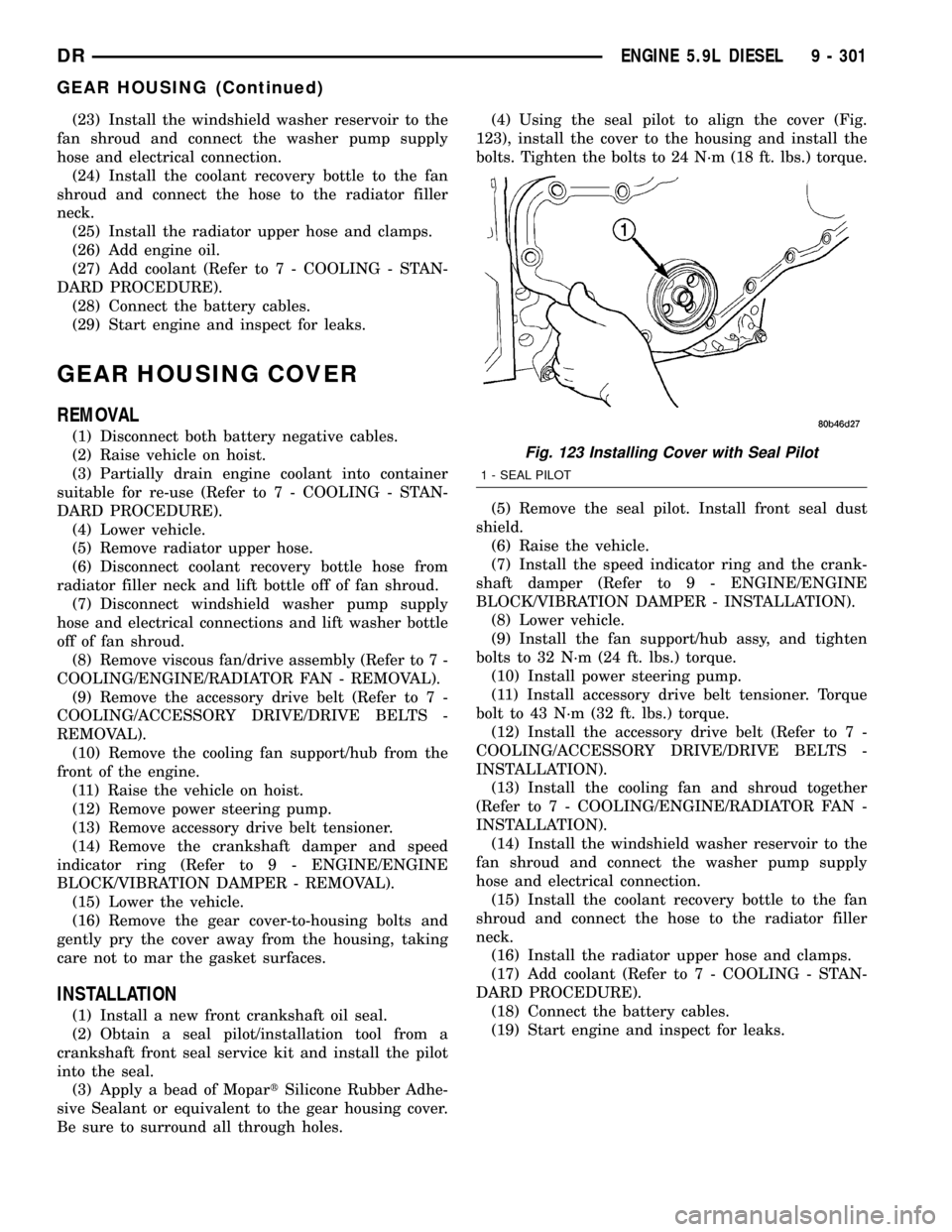
Be sure to surround all through holes.(4) Using the seal pilot to align the cover (Fig.
123), install the cover to the housing and install the
bolts. Tighten the bolts to 24 N´m (18 ft. lbs.) torque.
(5) Remove the seal pilot. Install front seal dust
shield.
(6) Raise the vehicle.
(7) Install the speed indicator ring and the crank-
shaft damper (Refer to 9 - ENGINE/ENGINE
BLOCK/VIBRATION DAMPER - INSTALLATION).
(8) Lower vehicle.
(9) Install the fan support/hub assy, and tighten
bolts to 32 N´m (24 ft. lbs.) torque.
(10) Install power steering pump.
(11) Install accessory drive belt tensioner. Torque
bolt to 43 N´m (32 ft. lbs.) torque.
(12) Install the accessory drive belt (Refer to 7 -
COOLING/ACCESSORY DRIVE/DRIVE BELTS -
INSTALLATION).
(13) Install the cooling fan and shroud together
(Refer to 7 - COOLING/ENGINE/RADIATOR FAN -
INSTALLATION).
(14) Install the windshield washer reservoir to the
fan shroud and connect the washer pump supply
hose and electrical connection.
(15) Install the coolant recovery bottle to the fan
shroud and connect the hose to the radiator filler
neck.
(16) Install the radiator upper hose and clamps.
(17) Add coolant (Refer to 7 - COOLING - STAN-
DARD PROCEDURE).
(18) Connect the battery cables.
(19) Start engine and inspect for leaks.
Fig. 123 Installing Cover with Seal Pilot
1 - SEAL PILOT
DRENGINE 5.9L DIESEL 9 - 301
GEAR HOUSING (Continued)
Page 1531 of 2627
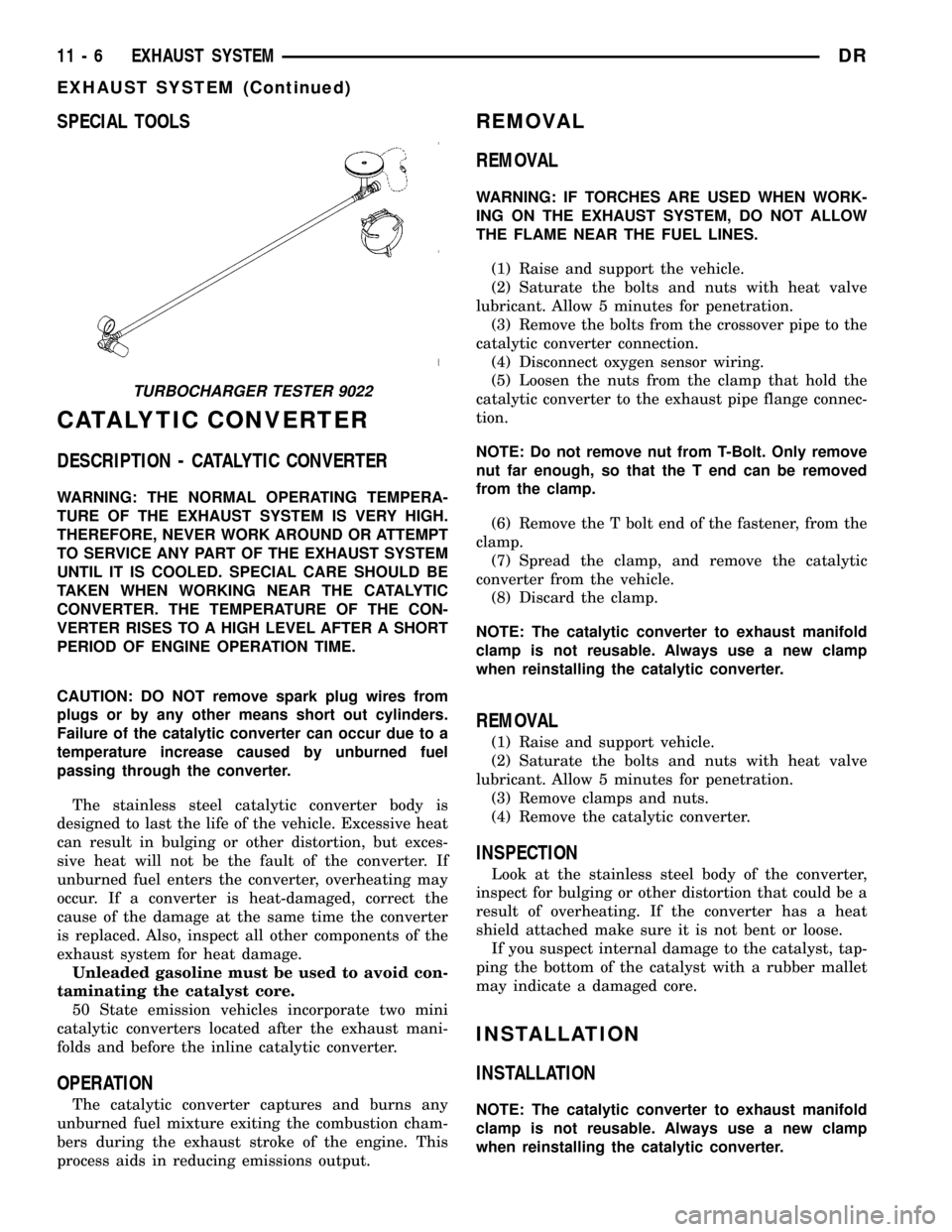
SPECIAL TOOLS
CATALYTIC CONVERTER
DESCRIPTION - CATALYTIC CONVERTER
WARNING: THE NORMAL OPERATING TEMPERA-
TURE OF THE EXHAUST SYSTEM IS VERY HIGH.
THEREFORE, NEVER WORK AROUND OR ATTEMPT
TO SERVICE ANY PART OF THE EXHAUST SYSTEM
UNTIL IT IS COOLED. SPECIAL CARE SHOULD BE
TAKEN WHEN WORKING NEAR THE CATALYTIC
CONVERTER. THE TEMPERATURE OF THE CON-
VERTER RISES TO A HIGH LEVEL AFTER A SHORT
PERIOD OF ENGINE OPERATION TIME.
CAUTION: DO NOT remove spark plug wires from
plugs or by any other means short out cylinders.
Failure of the catalytic converter can occur due to a
temperature increase caused by unburned fuel
passing through the converter.
The stainless steel catalytic converter body is
designed to last the life of the vehicle. Excessive heat
can result in bulging or other distortion, but exces-
sive heat will not be the fault of the converter. If
unburned fuel enters the converter, overheating may
occur. If a converter is heat-damaged, correct the
cause of the damage at the same time the converter
is replaced. Also, inspect all other components of the
exhaust system for heat damage.
Unleaded gasoline must be used to avoid con-
taminating the catalyst core.
50 State emission vehicles incorporate two mini
catalytic converters located after the exhaust mani-
folds and before the inline catalytic converter.
OPERATION
The catalytic converter captures and burns any
unburned fuel mixture exiting the combustion cham-
bers during the exhaust stroke of the engine. This
process aids in reducing emissions output.
REMOVAL
REMOVAL
WARNING: IF TORCHES ARE USED WHEN WORK-
ING ON THE EXHAUST SYSTEM, DO NOT ALLOW
THE FLAME NEAR THE FUEL LINES.
(1) Raise and support the vehicle.
(2) Saturate the bolts and nuts with heat valve
lubricant. Allow 5 minutes for penetration.
(3) Remove the bolts from the crossover pipe to the
catalytic converter connection.
(4) Disconnect oxygen sensor wiring.
(5) Loosen the nuts from the clamp that hold the
catalytic converter to the exhaust pipe flange connec-
tion.
NOTE: Do not remove nut from T-Bolt. Only remove
nut far enough, so that the T end can be removed
from the clamp.
(6) Remove the T bolt end of the fastener, from the
clamp.
(7) Spread the clamp, and remove the catalytic
converter from the vehicle.
(8) Discard the clamp.
NOTE: The catalytic converter to exhaust manifold
clamp is not reusable. Always use a new clamp
when reinstalling the catalytic converter.
REMOVAL
(1) Raise and support vehicle.
(2) Saturate the bolts and nuts with heat valve
lubricant. Allow 5 minutes for penetration.
(3) Remove clamps and nuts.
(4) Remove the catalytic converter.
INSPECTION
Look at the stainless steel body of the converter,
inspect for bulging or other distortion that could be a
result of overheating. If the converter has a heat
shield attached make sure it is not bent or loose.
If you suspect internal damage to the catalyst, tap-
ping the bottom of the catalyst with a rubber mallet
may indicate a damaged core.
INSTALLATION
INSTALLATION
NOTE: The catalytic converter to exhaust manifold
clamp is not reusable. Always use a new clamp
when reinstalling the catalytic converter.
TURBOCHARGER TESTER 9022
11 - 6 EXHAUST SYSTEMDR
EXHAUST SYSTEM (Continued)
Page 1540 of 2627

(9) Remove the turbocharger and gasket from the
exhaust manifold.
(10) If the turbocharger is not to be installed
immediately, cover the opening to prevent material
from entering into the manifold.
(11) If replacing the turbocharger, transfer the tur-
bocharger oil supply fitting to the new assembly.
Tighten fitting to 36 N´m (27 ft. lbs.).
(12) Clean and inspect the sealing surface.
CAUTION: The turbocharger is only serviced as an
assembly. Do not attempt to repair the turbocharger
as turbocharger and/or engine damage can result.
CLEANING
WARNING: To prevent damage or personal injury,
do not use a combustable cleaner to clean the tur-
bocharger.
Clean the turbocharger and exhaust manifold
mounting surfaces with a suitable scraper.
INSPECTION
Visually inspect the turbocharger and exhaust
manifold gasket surfaces. Replace stripped or eroded
mounting studs.
(1) Visually inspect the turbocharger for cracks.
The following cracks are NOT acceptable:
²Cracks in the turbine and compressor housing
that go completely through.
²Cracks in the mounting flange that are longer
than 15 mm (0.6 in.).
²Cracks in the mounting flange that intersect
bolt through-holes.
²Two (2) Cracks in the mounting flange that are
closer than 6.4 mm (0.25 in.) together.
(2) Visually inspect the impeller and compressor
wheel fins for nicks, cracks, or chips. Note: Some
impellers may have a factory placed paint mark
which, after normal operation, appears to be a crack.
Remove this mark with a suitable solvent to verify
that it is not a crack.
(3) Visually inspect the turbocharger compressor
housing for an impeller rubbing condition (Fig. 20).
Replace the turbocharger if the condition exists.
(4) Measure the turbocharger axial end play:
(a) Install a dial indicator as shown in (Fig. 21).
Zero the indicator at one end of travel.
(b) Move the impeller shaft fore and aft and
record the measurement. Allowable end play is
0.026 mm (0.0001 in.) MIN. and 0.127 mm (0.005
in.) MAX. If the recorded measurement falls out-
side these parameters, replace the turbocharger
assembly.(5) Measure the turbocharger bearing radial clear-
ance:
(a) Insert a narrow blade or wire style feeler
gauge between the compressor wheel and the hous-
ing (Fig. 22).
(b) Gently push the compressor wheel toward
the housing and record the clearance.
(c) With the feeler gauge in the same location,
gently push the compressor wheel away from the
housing and again record the clearance.
(d) Subtract the smaller clearance from the
larger clearance. This is the radial bearing clear-
ance.
(e) Allowable radial bearing clearance is 0.33
mm (0.013 in.) MIN. and 0.50 mm (0.020 in.) MAX.
If the recorded measurement falls outside these
specifications, replace the turbocharger assembly.
INSTALLATION
(1) Install the turbocharger. Apply anti-seize to the
studs and then tighten the turbocharger mounting
nuts to 43 N´m (32 ft. lbs.) torque.
Fig. 20 Inspect Compressor Housing for Impeller
Rubbing Condition
Fig. 21 Measure Turbocharger Axial End Play
DREXHAUST SYSTEM 11 - 15
TURBOCHARGER (Continued)
Page 1542 of 2627
CAUTION: Do not apply more than 138 kPa (20 psi)
air pressure to the charge air cooler system, sever
damage to the charge air cooler system may occur.
(3) Connect a regulated air supply to air fitting on
Tool 9022 Adapter. Set air pressure to a Maximum of
138 kPa (20 psi).
(4) Using soapy water check the rubber sleeves,
charge air cooler and intake manifold for leaks.
REMOVAL
WARNING: IF THE ENGINE WAS JUST TURNED
OFF, THE AIR INTAKE SYSTEM TUBES MAY BE
HOT.
(1) Disconnect the battery negative cables.
(2) Discharge the A/C system (Refer to 24 - HEAT-
ING & AIR CONDITIONING/PLUMBING - STAN-
DARD PROCEDURE) and remove the A/C condenser
(Refer to 24 - HEATING & AIR CONDITIONING/
PLUMBING/A/C CONDENSER - REMOVAL) (if A/C
equipped).
(3) Remove the transmission auxiliary cooler
(Refer to 7 - COOLING/TRANSMISSION/TRANS
COOLER - REMOVAL).
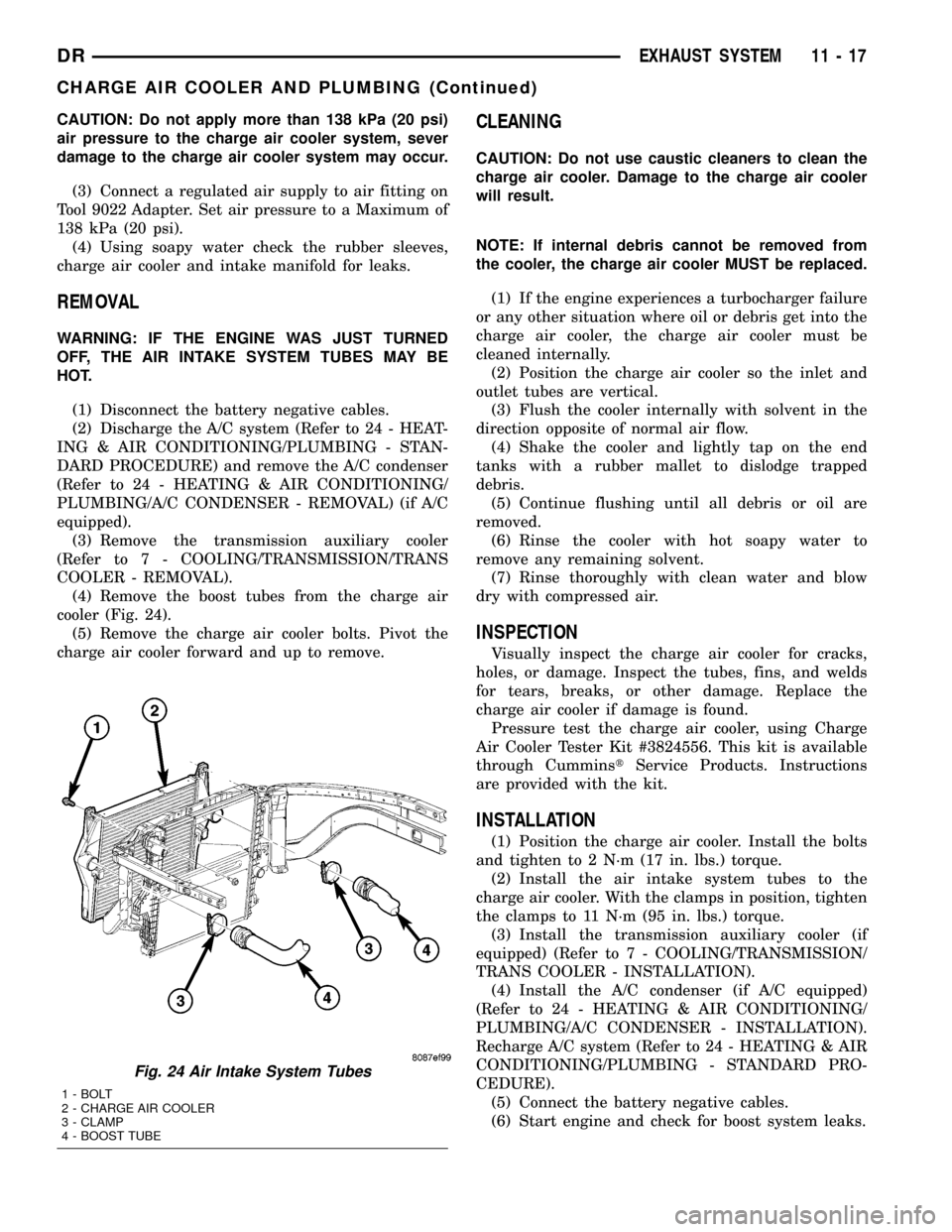
(4) Remove the boost tubes from the charge air
cooler (Fig. 24).
(5) Remove the charge air cooler bolts. Pivot the
charge air cooler forward and up to remove.
CLEANING
CAUTION: Do not use caustic cleaners to clean the
charge air cooler. Damage to the charge air cooler
will result.
NOTE: If internal debris cannot be removed from
the cooler, the charge air cooler MUST be replaced.
(1) If the engine experiences a turbocharger failure
or any other situation where oil or debris get into the
charge air cooler, the charge air cooler must be
cleaned internally.
(2) Position the charge air cooler so the inlet and
outlet tubes are vertical.
(3) Flush the cooler internally with solvent in the
direction opposite of normal air flow.
(4) Shake the cooler and lightly tap on the end
tanks with a rubber mallet to dislodge trapped
debris.
(5) Continue flushing until all debris or oil are
removed.
(6) Rinse the cooler with hot soapy water to
remove any remaining solvent.
(7) Rinse thoroughly with clean water and blow
dry with compressed air.
INSPECTION
Visually inspect the charge air cooler for cracks,
holes, or damage. Inspect the tubes, fins, and welds
for tears, breaks, or other damage. Replace the
charge air cooler if damage is found.
Pressure test the charge air cooler, using Charge
Air Cooler Tester Kit #3824556. This kit is available
through CumminstService Products. Instructions
are provided with the kit.
INSTALLATION
(1) Position the charge air cooler. Install the bolts
and tighten to 2 N´m (17 in. lbs.) torque.
(2) Install the air intake system tubes to the
charge air cooler. With the clamps in position, tighten
the clamps to 11 N´m (95 in. lbs.) torque.
(3) Install the transmission auxiliary cooler (if
equipped) (Refer to 7 - COOLING/TRANSMISSION/
TRANS COOLER - INSTALLATION).
(4) Install the A/C condenser (if A/C equipped)
(Refer to 24 - HEATING & AIR CONDITIONING/
PLUMBING/A/C CONDENSER - INSTALLATION).
Recharge A/C system (Refer to 24 - HEATING & AIR
CONDITIONING/PLUMBING - STANDARD PRO-
CEDURE).
(5) Connect the battery negative cables.
(6) Start engine and check for boost system leaks.
Fig. 24 Air Intake System Tubes
1 - BOLT
2 - CHARGE AIR COOLER
3 - CLAMP
4 - BOOST TUBE
DREXHAUST SYSTEM 11 - 17
CHARGE AIR COOLER AND PLUMBING (Continued)