Page 1893 of 2627

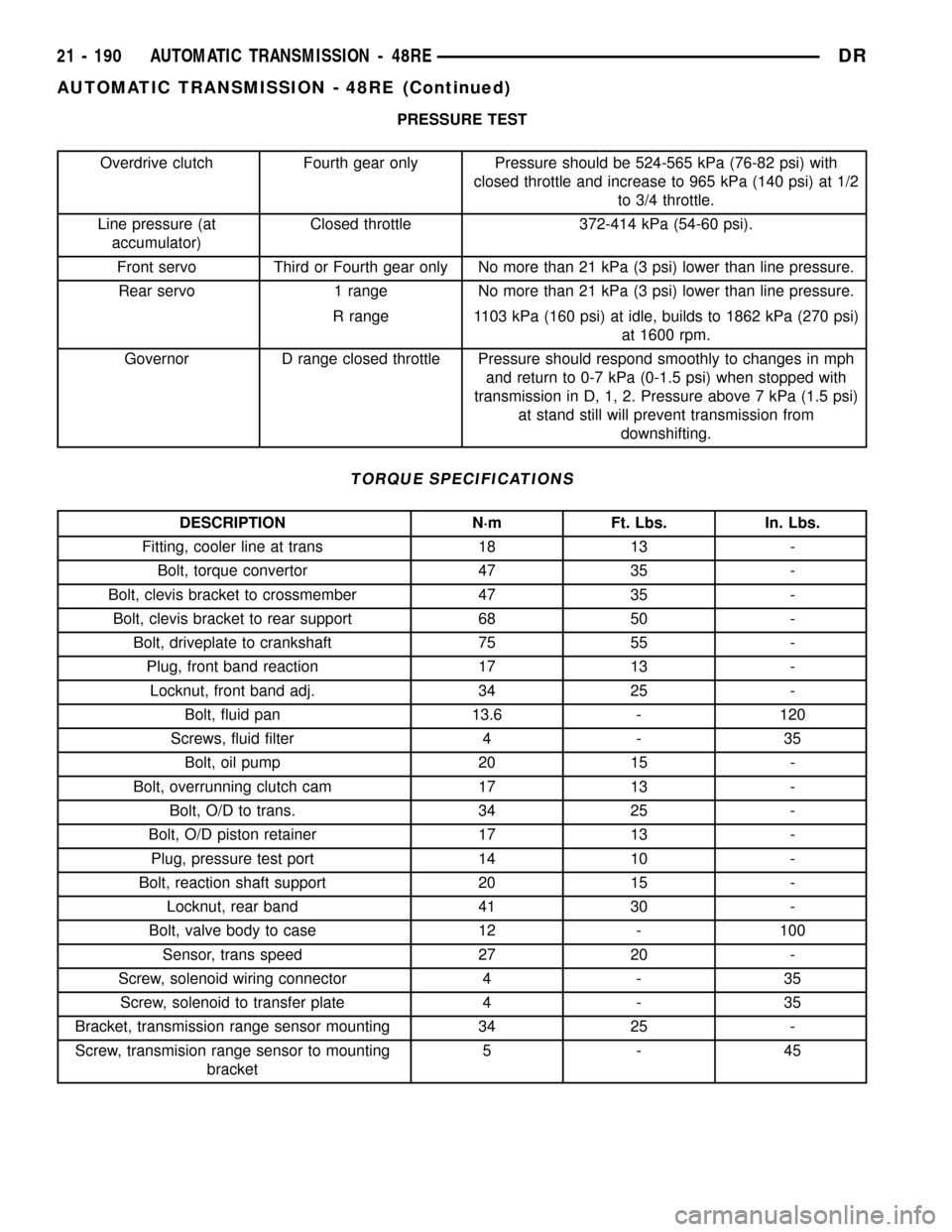
PRESSURE TEST
Overdrive clutch Fourth gear only Pressure should be 524-565 kPa (76-82 psi) with
closed throttle and increase to 965 kPa (140 psi) at 1/2
to 3/4 throttle.
Line pressure (at
accumulator)Closed throttle 372-414 kPa (54-60 psi).
Front servo Third or Fourth gear only No more than 21 kPa (3 psi) lower than line pressure.
Rear servo 1 range No more than 21 kPa (3 psi) lower than line pressure.
R range 1103 kPa (160 psi) at idle, builds to 1862 kPa (270 psi)
at 1600 rpm.
Governor D range closed throttle Pressure should respond smoothly to changes in mph
and return to 0-7 kPa (0-1.5 psi) when stopped with
transmission in D, 1, 2. Pressure above 7 kPa (1.5 psi)
at stand still will prevent transmission from
downshifting.
TORQUE SPECIFICATIONS
DESCRIPTION N´m Ft. Lbs. In. Lbs.
Fitting, cooler line at trans 18 13 -
Bolt, torque convertor 47 35 -
Bolt, clevis bracket to crossmember 47 35 -
Bolt, clevis bracket to rear support 68 50 -
Bolt, driveplate to crankshaft 75 55 -
Plug, front band reaction 17 13 -
Locknut, front band adj. 34 25 -
Bolt, fluid pan 13.6 - 120
Screws, fluid filter 4 - 35
Bolt, oil pump 20 15 -
Bolt, overrunning clutch cam 17 13 -
Bolt, O/D to trans. 34 25 -
Bolt, O/D piston retainer 17 13 -
Plug, pressure test port 14 10 -
Bolt, reaction shaft support 20 15 -
Locknut, rear band 41 30 -
Bolt, valve body to case 12 - 100
Sensor, trans speed 27 20 -
Screw, solenoid wiring connector 4 - 35
Screw, solenoid to transfer plate 4 - 35
Bracket, transmission range sensor mounting 34 25 -
Screw, transmision range sensor to mounting
bracket5-45
21 - 190 AUTOMATIC TRANSMISSION - 48REDR
AUTOMATIC TRANSMISSION - 48RE (Continued)
Page 2061 of 2627

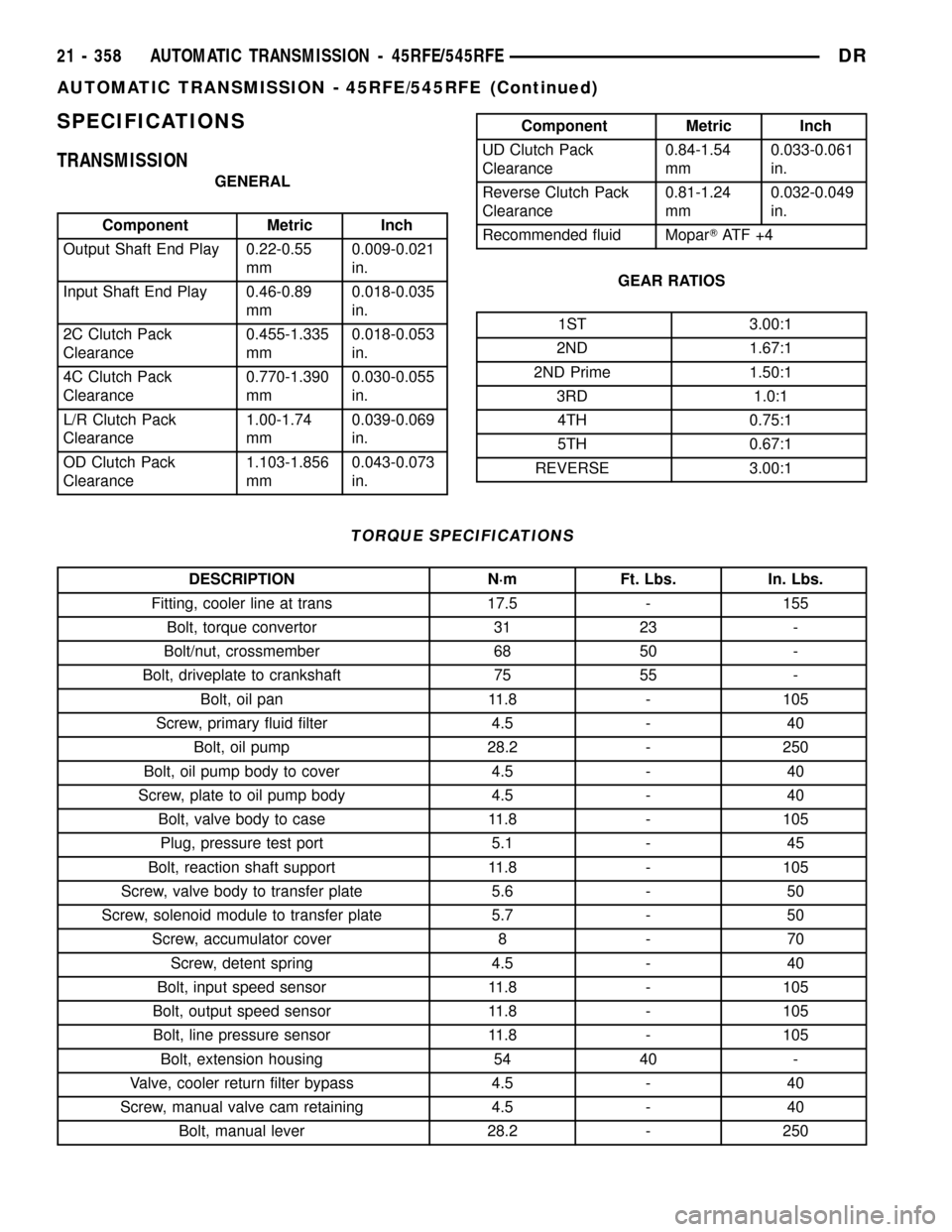
SPECIFICATIONS
TRANSMISSION
GENERAL
Component Metric Inch
Output Shaft End Play 0.22-0.55
mm0.009-0.021
in.
Input Shaft End Play 0.46-0.89
mm0.018-0.035
in.
2C Clutch Pack
Clearance0.455-1.335
mm0.018-0.053
in.
4C Clutch Pack
Clearance0.770-1.390
mm0.030-0.055
in.
L/R Clutch Pack
Clearance1.00-1.74
mm0.039-0.069
in.
OD Clutch Pack
Clearance1.103-1.856
mm0.043-0.073
in.
Component Metric Inch
UD Clutch Pack
Clearance0.84-1.54
mm0.033-0.061
in.
Reverse Clutch Pack
Clearance0.81-1.24
mm0.032-0.049
in.
Recommended fluid MoparTAT F + 4
GEAR RATIOS
1ST 3.00:1
2ND 1.67:1
2ND Prime 1.50:1
3RD 1.0:1
4TH 0.75:1
5TH 0.67:1
REVERSE 3.00:1
TORQUE SPECIFICATIONS
DESCRIPTION N´m Ft. Lbs. In. Lbs.
Fitting, cooler line at trans 17.5 - 155
Bolt, torque convertor 31 23 -
Bolt/nut, crossmember 68 50 -
Bolt, driveplate to crankshaft 75 55 -
Bolt, oil pan 11.8 - 105
Screw, primary fluid filter 4.5 - 40
Bolt, oil pump 28.2 - 250
Bolt, oil pump body to cover 4.5 - 40
Screw, plate to oil pump body 4.5 - 40
Bolt, valve body to case 11.8 - 105
Plug, pressure test port 5.1 - 45
Bolt, reaction shaft support 11.8 - 105
Screw, valve body to transfer plate 5.6 - 50
Screw, solenoid module to transfer plate 5.7 - 50
Screw, accumulator cover 8 - 70
Screw, detent spring 4.5 - 40
Bolt, input speed sensor 11.8 - 105
Bolt, output speed sensor 11.8 - 105
Bolt, line pressure sensor 11.8 - 105
Bolt, extension housing 54 40 -
Valve, cooler return filter bypass 4.5 - 40
Screw, manual valve cam retaining 4.5 - 40
Bolt, manual lever 28.2 - 250
21 - 358 AUTOMATIC TRANSMISSION - 45RFE/545RFEDR
AUTOMATIC TRANSMISSION - 45RFE/545RFE (Continued)
Page 2111 of 2627

INSTALLATION
(1) Place TRS selector plate in the PARK position.
(2) Position the transmission solenoid/TRS assem-
bly onto the valve body. Be sure that both alignment
dowels are fully seated in the valve body and that
the TRS switch contacts are properly positioned in
the selector plate
(3) Install the screws to hold the transmission
solenoid/TRS assembly onto the valve body.
(4) Tighten the solenoid assembly screws adjacent
to the arrows cast into the bottom of the valve body
first. Tighten the screws to 5.7 N´m (50 in.lbs.).
(5) Tighten the remainder of the solenoid assembly
screws to 5.7 N´m (50 in.lbs.).
(6) Install the valve body into the transmission.
TRANSMISSION
TEMPERATURE SENSOR
DESCRIPTION
The transmission temperature sensor is a ther-
mistor that is integral to the Transmission Range
Sensor (TRS).
OPERATION
The transmission temperature sensor is used by
the TCM to sense the temperature of the fluid in the
sump. Since fluid temperature can affect transmis-
sion shift quality and convertor lock up, the TCM
requires this information to determine which shift
schedule to operate in.
Calculated Temperature
A failure in the temperature sensor or circuit will
result in calculated temperature being substituted for
actual temperature. Calculated temperature is a pre-
dicted fluid temperature which is calculated from a
combination of inputs:
²Battery (ambient) temperature
²Engine coolant temperature
²In-gear run time since start-up
VALVE BODY
DESCRIPTION
The valve body consists of a cast aluminum valve
body, a separator plate, and a transfer plate. The
valve body contains valves and check balls that con-
trol fluid delivery to the torque converter clutch,
bands, and frictional clutches. The valve body con-
tains the following components (Fig. 129) and (Fig.
130):
²Solenoid switch valve
²Manual valve
²Low/reverse switch valve
²5 Accumulators
²7 check balls
OPERATION
NOTE: Refer to the Hydraulic Schematics for a
visual aid in determining valve location, operation
and design.
SOLENOID SWITCH VALVE
The Solenoid Switch Valve (SSV) controls the direc-
tion of the transmission fluid when the L/R-TCC sole-
noid is energized.
When shifting into 1st gear, a special hydraulic
sequence is performed to ensure SSV movement into
the downshifted position. The L/R pressure switch is
monitored to confirm SSV movement. If the move-
ment is not confirmed (the L/R pressure switch does
not close), 2nd gear is substituted for 1st. A DTC will
be set after three unsuccessful attempts are made to
get into 1st gear in one given key start.
MANUAL VALVE
The manual valve is a relay valve. The purpose of
the manual valve is to direct fluid to the correct cir-
cuit needed for a specific gear or driving range. The
manual valve, as the name implies, is manually oper-
ated by the driver with a lever located on the top of
the valve body. The valve is connected mechanically
by a cable to the gearshift mechanism. The valve is
held in each of its positions by a roller detent spring
(Fig. 131) that engages the ªroostercombº of the TRS
selector plate.
21 - 408 AUTOMATIC TRANSMISSION - 45RFE/545RFEDR
TRANSMISSION SOLENOID/TRS ASSEMBLY (Continued)