1998 DODGE RAM 1500 light
[x] Cancel search: lightPage 1490 of 2627
After removing the boring bar, use a honing stone
to chamfer the corner of the repair sleeve(s).
SLEEVE MACHINING DIMENSIONS CHART
ITEM MEASUREMENT
SLEEVE PROTRUSION MIN. - FLUSH WITH
BLOCK
MAX. - 0.050 mm
(0.0019 in.)
SLEEVE DIAMETER 101.956 mm (4.014 in.)
SLEEVE CHAMFER APPROX. 1.25 mm
(0.049 in.) by 15É
A correctly honed surface will have a crosshatch
appearance with the lines at 15É to 25É angles with
the top of the cylinder block. For the rough hone, use
80 grit honing stones. To finish hone, use 280 grit
honing stones.
Finished bore inside dimension is 102.020 0.020
mm (4.0165 0.0008 inch).
A maximum of 1.2 micrometer (48 microinch) sur-
face finish must be obtained.
After finish honing is complete, immediately clean
the cylinder bores with a strong solution of laundry
detergent and hot water.
After rinsing, blow the block dry with compressed
air.
Wipe the bore with a white, lint-free, lightly oiled
cloth. Make sure there is no grit residue present.
Apply a rust-preventing compound if the block will
not be used immediately.
A standard diameter piston and a piston ring set
must be used with a sleeved cylinder bore.
STANDARD PROCEDUREÐCAM BORE REPAIR
For standard bushings, not oversized, maximum
front and rear cam bushing bore diameter is 59.248
mm. (2.3326 in.). DO NOT bore the intermediate cam
bore to the front cam bore oversize dimensions. Max-
imum front and rear camshaft bushing installed
diameter is 54.147 mm. (2.1318 in.). Minimum
installed diameter is 54.083 mm. (2.1293 in.). Maxi-
mum intermediate camshaft bore diameter is 54.164
mm. (2.1324 in.).
A surface finish of 2.3 micrometers (92 microinch)
must be maintained. Not more than 20% of an area
of any one bore may be 3.2 micrometers (126 micro-
inch).
Camshaft bores can be repaired individually. It is
not necessary to repair undamaged cam bores in
order to repair individually damaged cam bores. The
standard front bushing cannot be used to repair
intermediate bores.Install all cam bushings flush or below the front
and rear cam bore surface. The front camshaft bush-
ing should be installed flush with front face of block.
The rear camshaft bushing should be installed flush
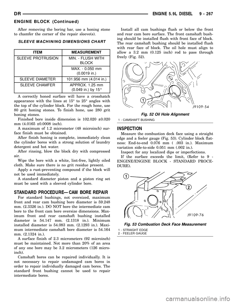
with rear face of block. The oil hole must align to
allow a 3.2 mm (0.125 inch) rod to pass through
freely (Fig. 52).
INSPECTION
Measure the combustion deck face using a straight
edge and a feeler gauge (Fig. 53). Cylinder block flat-
ness: End-to-end 0.076 mm ( .003 in.). Maximum
variation side-to-side 0.051 mm (.002 in.).
Inspect for any localized dips or imperfections.
If the surface exceeds the limit, (Refer to 9 -
ENGINE/ENGINE BLOCK - STANDARD PROCE-
DURE).
Fig. 52 Oil Hole Alignment
1 - CAMSHAFT BUSHING
Fig. 53 Combustion Deck Face Measurement
1 - STRAIGHT EDGE
2 - FEELER GAUGE
DRENGINE 5.9L DIESEL 9 - 267
ENGINE BLOCK (Continued)
Page 1500 of 2627
(7) Install the flywheel or converter drive plate.
Tighten the bolts to 137 N´m (101 ft. lbs.) torque.
(8) Install the clutch cover and disc (if equipped)
(Refer to 6 - CLUTCH/CLUTCH DISC - INSTALLA-
TION).
(9) Install the transmission and transfer case (if
equipped).
(10) Lower vehicle.
(11) Connect battery negative cables.
(12) Check engine oil level and adjust, if necessary.
(13) Start engine and check for oil leaks.
CRANKSHAFT REAR OIL SEAL
RETAINER
REMOVAL
(1) Disconnect the battery negative cables.
(2) Raise vehicle on hoist.
(3) Remove the oil pan drain plug and drain the
engine oil. Re-install plug and torque to 50 N´m (44
ft. lbs.) torque.
(4) Remove transmission and transfer case (if
equipped) from vehicle.
(5)
Remove flywheel or torque converter drive plate.
(6) Disconnect starter cables from starter motor.
(7) Remove starter motor (Refer to 8 - ELECTRI-
CAL/STARTING/STARTER MOTOR - REMOVAL)
and transmission adapter plate assembly.
(8) Remove four (4) oil pan rear bolts. Slide a
feeler gauge between the seal retainer and oil pan
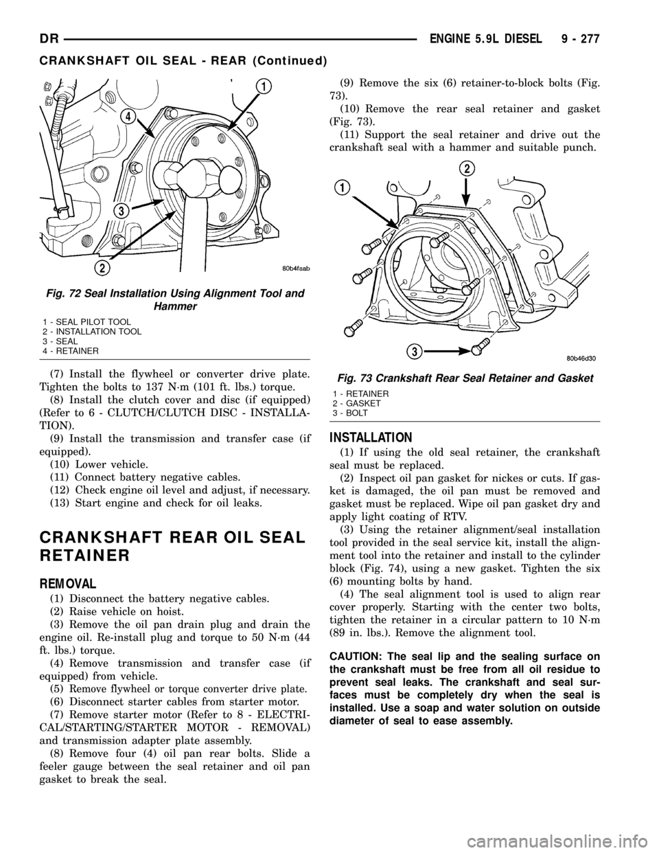
gasket to break the seal.(9) Remove the six (6) retainer-to-block bolts (Fig.
73).
(10) Remove the rear seal retainer and gasket
(Fig. 73).
(11) Support the seal retainer and drive out the
crankshaft seal with a hammer and suitable punch.
INSTALLATION
(1) If using the old seal retainer, the crankshaft
seal must be replaced.
(2) Inspect oil pan gasket for nickes or cuts. If gas-
ket is damaged, the oil pan must be removed and
gasket must be replaced. Wipe oil pan gasket dry and
apply light coating of RTV.
(3) Using the retainer alignment/seal installation
tool provided in the seal service kit, install the align-
ment tool into the retainer and install to the cylinder
block (Fig. 74), using a new gasket. Tighten the six
(6) mounting bolts by hand.
(4) The seal alignment tool is used to align rear
cover properly. Starting with the center two bolts,
tighten the retainer in a circular pattern to 10 N´m
(89 in. lbs.). Remove the alignment tool.
CAUTION: The seal lip and the sealing surface on
the crankshaft must be free from all oil residue to
prevent seal leaks. The crankshaft and seal sur-
faces must be completely dry when the seal is
installed. Use a soap and water solution on outside
diameter of seal to ease assembly.
Fig. 72 Seal Installation Using Alignment Tool and
Hammer
1 - SEAL PILOT TOOL
2 - INSTALLATION TOOL
3 - SEAL
4 - RETAINER
Fig. 73 Crankshaft Rear Seal Retainer and Gasket
1 - RETAINER
2 - GASKET
3 - BOLT
DRENGINE 5.9L DIESEL 9 - 277
CRANKSHAFT OIL SEAL - REAR (Continued)
Page 1509 of 2627
INSTALLATION
(1) Install speed indicator ring.
NOTE: The speed indicator ring is located over a
dowel pin.
(2) Install the crankshaft damper and bolts.
Tighten bolts to 40 N´m (30 ft. lbs.) torque, plus an
additional 60É.
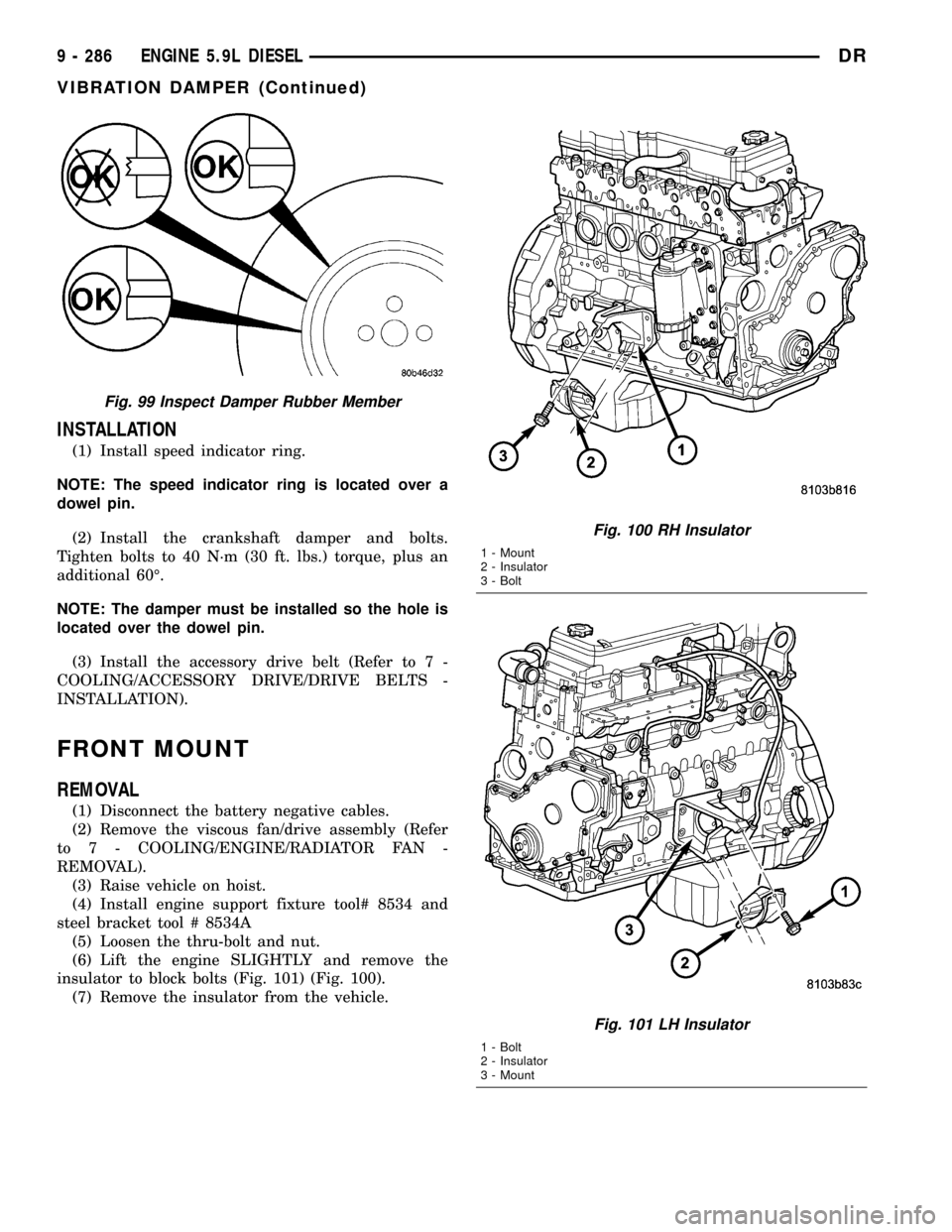
NOTE: The damper must be installed so the hole is
located over the dowel pin.
(3) Install the accessory drive belt (Refer to 7 -
COOLING/ACCESSORY DRIVE/DRIVE BELTS -
INSTALLATION).
FRONT MOUNT
REMOVAL
(1) Disconnect the battery negative cables.
(2) Remove the viscous fan/drive assembly (Refer
to 7 - COOLING/ENGINE/RADIATOR FAN -
REMOVAL).
(3) Raise vehicle on hoist.
(4) Install engine support fixture tool# 8534 and
steel bracket tool # 8534A
(5) Loosen the thru-bolt and nut.
(6) Lift the engine SLIGHTLY and remove the
insulator to block bolts (Fig. 101) (Fig. 100).
(7) Remove the insulator from the vehicle.
Fig. 99 Inspect Damper Rubber Member
Fig. 100 RH Insulator
1 - Mount
2 - Insulator
3 - Bolt
Fig. 101 LH Insulator
1 - Bolt
2 - Insulator
3 - Mount
9 - 286 ENGINE 5.9L DIESELDR
VIBRATION DAMPER (Continued)
Page 1510 of 2627
INSTALLATION
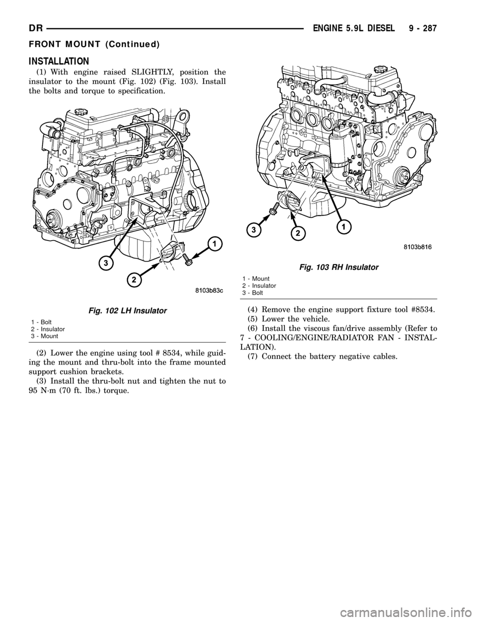
(1) With engine raised SLIGHTLY, position the
insulator to the mount (Fig. 102) (Fig. 103). Install
the bolts and torque to specification.
(2) Lower the engine using tool # 8534, while guid-
ing the mount and thru-bolt into the frame mounted
support cushion brackets.
(3) Install the thru-bolt nut and tighten the nut to
95 N´m (70 ft. lbs.) torque.(4) Remove the engine support fixture tool #8534.
(5) Lower the vehicle.
(6) Install the viscous fan/drive assembly (Refer to
7 - COOLING/ENGINE/RADIATOR FAN - INSTAL-
LATION).
(7) Connect the battery negative cables.
Fig. 102 LH Insulator
1 - Bolt
2 - Insulator
3 - Mount
Fig. 103 RH Insulator
1 - Mount
2 - Insulator
3 - Bolt
DRENGINE 5.9L DIESEL 9 - 287
FRONT MOUNT (Continued)
Page 1511 of 2627
REAR MOUNT
REMOVAL
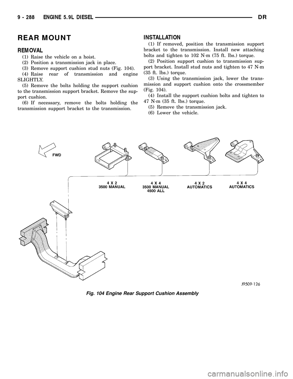
(1) Raise the vehicle on a hoist.
(2) Position a transmission jack in place.
(3) Remove support cushion stud nuts (Fig. 104).
(4) Raise rear of transmission and engine
SLIGHTLY.
(5) Remove the bolts holding the support cushion
to the transmission support bracket. Remove the sup-
port cushion.
(6) If necessary, remove the bolts holding the
transmission support bracket to the transmission.
INSTALLATION
(1) If removed, position the transmission support
bracket to the transmission. Install new attaching
bolts and tighten to 102 N´m (75 ft. lbs.) torque.
(2) Position support cushion to transmission sup-
port bracket. Install stud nuts and tighten to 47 N´m
(35 ft. lbs.) torque.
(3) Using the transmission jack, lower the trans-
mission and support cushion onto the crossmember
(Fig. 104).
(4) Install the support cushion bolts and tighten to
47 N´m (35 ft. lbs.) torque.
(5) Remove the transmission jack.
(6) Lower the vehicle.
Fig. 104 Engine Rear Support Cushion Assembly
9 - 288 ENGINE 5.9L DIESELDR
Page 1516 of 2627
OIL COOLER & LINES
CLEANING
CLEANING AND INSPECTION
Clean the sealing surfaces.
Apply 483 kPa (70 psi) air pressure to the element
to check for leaks. If the element leaks, replace the
element.
OIL FILTER
REMOVAL
(1) Clean the area around the oil filter head.
Remove the filter from below using a cap-style filter
wrench.
(2) Clean the gasket surface of the filter head. The
filter canister O-Ring seal can stick on the filter
head. Make sure it is removed.
INSTALLATION
(1) Fill the oil filter element with clean oil before
installation. Use the same type oil that will be used
in the engine.
(2) Apply a light film of lubricating oil to the seal-
ing surface before installing the filter.
CAUTION: Mechanical over-tightening may distort
the threads or damage the filter element seal.
(3) Install the filter until it contacts the sealing
surface of the oil filter adapter. Tighten filter an
additional
1¤2turn.
OIL PAN
REMOVAL
(1) Disconnect the battery negative cables.
(2) Install engine support fixture # 8534.
(3) Raise vehicle on hoist.
(4) Disconnect starter cables from starter motor.
(5) Remove transmission and transfer case (if
equipped).
(6) Remove flywheel or flexplate.
(7) Remove starter motor (Refer to 8 - ELECTRI-
CAL/STARTING/STARTER MOTOR - REMOVAL)
and transmission adapter plate assembly.
WARNING: HOT OIL CAN CAUSE PERSONAL
INJURY.
(8) Drain the engine oil (Refer to 9 - ENGINE/LU-
BRICATION/OIL - STANDARD PROCEDURE).(9) Install the oil pan drain plug if sealing surface
is not damaged and tighten to 50 N´m (37 ft. lbs.)
torque.
(10) Remove oil pan bolts, break the pan to block
seal, and lower pan slightly and remove oil suction
tube fasteners.
(11) Remove oil pan and suction tube.
CLEANING
Remove all gasket material from the oil pan and
cylinder block sealing surfaces. Extra effort may be
required around T-joint areas. Clean oil pan and
flush suction tube with a suitable solvent.
INSPECTION
Inspect the oil pan, suction tube, and tube braces
for cracks and damage. Replace any defective compo-
nent. Inspect the oil drain plug and drain hole
threads. Inspect the oil pan sealing surface for
straightness. Repair any minor imperfections with a
ball-peen hammer. Do not attempt to repair an oil
pan by welding.
INSTALLATION
(1) Fill the T-joint between the pan rail/gear hous-
ing and pan rail/rear seal retainer with sealant. Use
MopartSilicone Rubber Adhesive Sealant or equiva-
lent.
(2) Place suction tube in oil pan and guide them
into place. Using a new tube to block gasket, install
and tighten the suction tube bolts by hand. Starting
with the oil pump inlet bolts, tighten the bolts to 24
N´m (18 ft. lbs.) torque. Tighten the remaining tube
brace bolts to 43 N´m (32 ft. lbs.) torque.
(3) Starting in the center and working outward,
tighten the oil pan bolts to 28 N´m (21 ft. lbs.)
torque.
(4) Install the flywheel housing assembly with the
starter motor attached and tighten bolts to 77 N´m
(57 ft. lbs.) torque.
(5) Connect starter motor cables.
(6) Install the flywheel or flexplate. Torque to 137
N´m (101 ft. lbs.).
(7) Install transmission and transfer case (if
equipped).
(8) Lower vehicle.
(9) Remove the engine support fixture # 8534.
(10) Install battery negative cables.
(11) Fill the crankcase with new engine oil.
(12) Start engine and check for leaks. Stop engine,
check oil level, and adjust, if necessary.
DRENGINE 5.9L DIESEL 9 - 293
Page 1526 of 2627
EXHAUST SYSTEM
TABLE OF CONTENTS
page page
EXHAUST SYSTEM
DESCRIPTION
DESCRIPTION........................1
DESCRIPTION - 5.9L DIESEL.............3
DIAGNOSIS AND TESTING
DIAGNOSIS AND TESTING - GAS ENGINE . . . 4
DIAGNOSIS AND TESTING - DIESEL
ENGINE..............................5
SPECIFICATIONS - TORQUE...............5
SPECIAL TOOLS........................6
CATALYTIC CONVERTER
DESCRIPTION - CATALYTIC CONVERTER.....6
OPERATION............................6
REMOVAL
REMOVAL............................6
REMOVAL............................6
INSPECTION...........................6
INSTALLATION
INSTALLATION........................6
INSTALLATION........................7
EXHAUST PIPE
REMOVAL - 3.7L/4.7L/5.7L.................7
INSPECTION...........................7
INSTALLATION - 3.7L/4.7L/5.7L..............7
EXHAUST PIPE
REMOVAL - DIESEL......................7
INSPECTION...........................8
INSTALLATION - DIESEL..................8
HEAT SHIELDS
DESCRIPTION..........................8
REMOVAL.............................8
INSTALLATION..........................8
MUFFLER
REMOVAL.............................9INSTALLATION..........................9
MUFFLER - 5.9L DIESEL
REMOVAL.............................10
INSTALLATION.........................10
TAILPIPE - 5.9L DIESEL
REMOVAL.............................10
INSPECTION..........................10
INSTALLATION.........................11
TAILPIPE
REMOVAL.............................11
INSPECTION..........................11
INSTALLATION.........................11
TURBOCHARGER SYSTEM
DIAGNOSIS AND TESTING -
TURBOCHARGER BOOST PRESSURE.....11
TURBOCHARGER
DESCRIPTION.........................12
OPERATION...........................13
REMOVAL.............................14
CLEANING............................15
INSPECTION..........................15
INSTALLATION.........................15
CHARGE AIR COOLER AND PLUMBING
DESCRIPTION.........................16
OPERATION...........................16
DIAGNOSIS AND TESTING - CHARGE AIR
COOLER SYSTEM - LEAKS..............16
REMOVAL.............................17
CLEANING............................17
INSPECTION..........................17
INSTALLATION.........................17
EXHAUST SYSTEM
DESCRIPTION
DESCRIPTION
CAUTION: Avoid application of rust prevention com-
pounds or undercoating materials to exhaust sys-
tem floor pan exhaust heat shields. Light overspray
near the edges is permitted. Application of coating
will result in excessive floor pan temperatures and
objectionable fumes.The federal gasoline engine exhaust system con-
sists of engine exhaust manifolds, exhaust pipes, cat-
alytic converter(s), extension pipe (if needed),
exhaust heat shields, muffler and exhaust tailpipe
(Fig. 1), (Fig. 2), (Fig. 3)
The California emission vehicles exhaust system
also contains the above components as well as mini
catalytic converters added to the exhaust pipe.
The exhaust system must be properly aligned to
prevent stress, leakage and body contact. Minimum
clearance between any exhaust component and the
body or frame is 25.4 mm (1.0 in.). If the system con-
tacts any body panel, it may amplify objectionable
noises from the engine or body.
DREXHAUST SYSTEM 11 - 1
Page 1528 of 2627
DESCRIPTION - 5.9L DIESEL
CAUTION: Avoid application of rust prevention com-
pounds or undercoating materials to exhaust sys-
tem floor pan exhaust heat shields. Light overspray
near the edges is permitted. Application of coating
will result in excessive floor pan temperatures and
objectionable fumes.
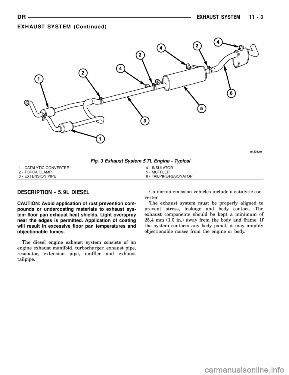
The diesel engine exhaust system consists of an
engine exhaust manifold, turbocharger, exhaust pipe,
resonator, extension pipe, muffler and exhaust
tailpipe.California emission vehicles include a catalytic con-
verter.
The exhaust system must be properly aligned to
prevent stress, leakage and body contact. The
exhaust components should be kept a minimum of
25.4 mm (1.0 in.) away from the body and frame. If
the system contacts any body panel, it may amplify
objectionable noises from the engine or body.
Fig. 3 Exhaust System 5.7L Engine - Typical
1 - CATALYTIC CONVERTER
2 - TORCA CLAMP
3 - EXTENSION PIPE4 - INSULATOR
5 - MUFFLER
6 - TAILPIPE/RESONATOR
DREXHAUST SYSTEM 11 - 3
EXHAUST SYSTEM (Continued)