1998 DODGE RAM 1500 Crank
[x] Cancel search: CrankPage 1449 of 2627
REMOVAL
(1) Disconnect negative cable from battery.
(2) Remove resonator assembly and air inlet hose.
(3) Disconnect electrical connectors for the follow-
ing components:
²Manifold Absolute Pressure (MAP) Sensor
²Intake Air Temperature (IAT) Sensor
²Throttle Position (TPS) Sensor
²Coolant Temperature (CTS) Sensor
(4) Disconnect brake booster hose and positive
crankcase ventilation (PCV) hose.
(5) Remove generator and set aside.
NOTE: It is not necessary to remove lines or
remove freon from A/C compressor.
(6) Remove air conditioning compressor and set
aside..
(7) Bleed fuel system (Refer to 14 - FUEL SYS-
TEM/FUEL DELIVERY - STANDARD PROCE-
DURE).
(8) Remove intake manifold retaining fasteners in
a crisscross pattern starting from the outside bolts
and ending at the middle bolts.
(9) Remove intake manifold and IAFM as an
assembly.
CLEANING
NOTE: There is NO approved repair procedure for
the intake manifold. If severe damage is found dur-
ing inspection, the intake manifold must be
replaced.
Before installing the intake manifold thoroughly
clean the mating surfaces. Use a suitable cleaning
solvent, then air dry.
INSPECTION
(1) Inspect the intake sealing surface for cracks,
nicks and distortion.
(2) Inspect the intake manifold vacuum hose fit-
tings for looseness or blockage.
(3) Inspect the manifold to throttle body mating
surface for cracks, nicks and distortion.
INSTALLATION
(1) Install intake manifold seals.
(2) Position intake manifold and IAFM.
(3) Install intake manifold retaining bolts, and
tighten in sequence from the middle bolts towards
the outside in a crisscross pattern. Torque fasteners
to 12 N´m (105 in. lbs.).
(4) Connect electrical connectors for the following
components:
²Manifold Absolute Pressure (MAP) Sensor
²Intake Air Temperature (IAT) Sensor²Throttle Position (TPS) Sensor
²Coolant Temperature (CTS) Sensor
²Idle Air Control (IAC) Motor
(5) Install generator.
(6) Install A/C compressor.
(7) Connect Brake booster hose and Positive crank-
case ventilation (PCV) hose.
(8) Install resonator assembly and air inlet hose.
(9) Connect negative cable to battery.
EXHAUST MANIFOLD
DESCRIPTION
The exhaust manifolds are log style with a pat-
ented flow enhancing design to maximize perfor-
mance. The exhaust manifolds are made of high
silicon molybdenum cast iron. A perforated core
graphite exhaust manifold gasket is used to improve
sealing to the cylinder head. The exhaust manifolds
are covered by a three layer laminated heat shield
for thermal protection and noise reduction. The heat
shields are fastened with a torque prevailing nut
that is backed off slightly to allow for the thermal
expansion of the exhaust manifold.
OPERATION
The exhaust manifolds collect the engine exhaust
exiting the combustion chambers, then channels the
exhaust gases to the exhaust pipes attached to the
manifolds.
REMOVAL
EXHAUST MANIFOLD
(1) Disconnect negative battery cable.
(2) Raise vehicle.
(3) Remove exhaust pipe to manifold bolts.
(4) Lower vehicle.
(5) Install engine support fixture special tool
#8534.
(6) Raise engine enough to remove manifolds.
CAUTION: Do not damage engine harness while
raising the engine.
(7) Remove heat shield.
(8) Remove manifold bolts.
(9) Remove manifold and gasket.
CLEANING
Clean mating surfaces on cylinder head and mani-
fold. Wash with solvent and blow dry with com-
pressed air.
9 - 226 ENGINE - 5.7LDR
INTAKE MANIFOLD (Continued)
Page 1450 of 2627
INSPECTION
Inspect manifold for cracks.
Inspect mating surfaces of manifold for flatness
with a straight edge. Gasket surfaces must be flat
within 0.2 mm per 300 mm (0.008 inch per foot).
INSTALLATION
EXHAUST MANIFOLD
(1) Install manifold gasket and manifold.
(2) Install manifold bolts and tighten to 25 N´m
(18 ft. lbs.).
(3) Install heat shield and tighten nuts to 15 N´m
(11 ft. lbs.).
(4) Lower engine.
CAUTION: Do not damage engine harness while
lowering the engine.
(5) Remove engine support fixture from engine.
(6) Raise vehicle.
(7) Tighten right and left side engine mount
through bolts.
(8) Install exhaust flange to pipe bolts.
(9) Lower vehicle.
(10) Connect negative battery cable.
TIMING/CHAIN COVER
REMOVAL
(1) Disconnect the battery negative cable.
(2) Remove air cleaner assembly.
(3) Drain cooling system.
(4) Remove accessory drive belt.
(5) Remove fan and fan drive assembly (Refer to 7
- COOLING/ENGINE/FAN DRIVE VISCOUS
CLUTCH - REMOVAL).
(6) Remove coolant bottle and washer bottle.
(7) Remove fan shroud.
NOTE: It is not necessary to disconnect A/C lines or
discharge freon.
(8) Remove A/C compressor and set aside.
(9) Remove the generator.
(10) Remove upper radiator hose.
(11) Disconnect both heater hoses at timing cover.
(12) Disconnect lower radiator hose at engine.
(13) Remove accessory drive belt tensioner and
both idler pulleys.
(14) Remove crankshaft damper(Refer to 9 -
ENGINE/ENGINE BLOCK/VIBRATION DAMPER -
REMOVAL).NOTE: Do not remove the hoses from the power
steering pump.
(15) Remove power steering pump and set aside.
(16) Remove the dipstick support bolt.
(17) Drain the engine oil.
(18) Remove the oil pan and pick up tube(Refer to
9 - ENGINE/LUBRICATION/OIL PAN - REMOVAL).
NOTE: It is not necessary to remove water pump for
timing cover removal.
(19) Remove timing cover bolts and remove cover.
INSTALLATION
(1) Clean timing chain cover and block surface.
NOTE: Always install a new gasket on timing cover.
(2) Install cover and new gasket. Tighten fasteners
to 28 N´m (250 in. lbs.).
NOTE: The large lifting stud is torqued to 55 N´m
(40 ft. lbs.).
(3) Install the oil pan and pick up tube(Refer to 9 -
ENGINE/LUBRICATION/OIL PAN - INSTALLA-
TION).
(4) Install the A/C compressor.
(5) Install the generator.
(6) Install power steering pump.
(7) Install the dipstick support bolt.
(8) Install the thermostat housing.
(9) Install crankshaft damper(Refer to 9 -
ENGINE/ENGINE BLOCK/VIBRATION DAMPER -
INSTALLATION).
(10) Install accessory drive belt tensioner assembly
and both idler pulleys.
(11) Install radiator lower hose.
(12) Install both heater hoses.
(13) Install radiator fan shroud.
(14) Install the fan and fan drive assembly
(15) Install the accessory drive belt.
(16) Install the coolant bottle and washer bottle.
(17) Install the upper radiator hose.
(18) Install the air cleaner assembly.
(19) Fill cooling system.
(20) Refill engine oil.
(21) Connect the battery negative cable.
DRENGINE - 5.7L 9 - 227
EXHAUST MANIFOLD (Continued)
Page 1451 of 2627
TIMING/CHAIN AND
SPROCKETS
REMOVAL
(1) Disconnect battery negative cable.
(2) Drain cooling system.
(3) Remove Timing Chain Cover.
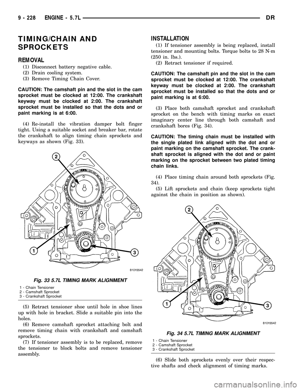
CAUTION: The camshaft pin and the slot in the cam
sprocket must be clocked at 12:00. The crankshaft
keyway must be clocked at 2:00. The crankshaft
sprocket must be installed so that the dots and or
paint marking is at 6:00.
(4) Re-install the vibration damper bolt finger
tight. Using a suitable socket and breaker bar, rotate
the crankshaft to align timing chain sprockets and
keyways as shown (Fig. 33).
(5) Retract tensioner shoe until hole in shoe lines
up with hole in bracket. Slide a suitable pin into the
holes.
(6) Remove camshaft sprocket attaching bolt and
remove timing chain with crankshaft and camshaft
sprockets.
(7) If tensioner assembly is to be replaced, remove
the tensioner to block bolts and remove tensioner
assembly.
INSTALLATION
(1) If tensioner assembly is being replaced, install
tensioner and mounting bolts. Torque bolts to 28 N´m
(250 in. lbs.).
(2) Retract tensioner if required.
CAUTION: The camshaft pin and the slot in the cam
sprocket must be clocked at 12:00. The crankshaft
keyway must be clocked at 2:00. The crankshaft
sprocket must be installed so that the dots and or
paint marking is at 6:00.
(3) Place both camshaft sprocket and crankshaft
sprocket on the bench with timing marks on exact
imaginary center line through both camshaft and
crankshaft bores (Fig. 34).
CAUTION: The timing chain must be installed with
the single plated link aligned with the dot and or
paint marking on the camshaft sprocket. The crank-
shaft sprocket is aligned with the dot and or paint
marking on the sprocket between two plated timing
chain links.
(4) Place timing chain around both sprockets (Fig.
34).
(5) Lift sprockets and chain (keep sprockets tight
against the chain in position as shown).
(6) Slide both sprockets evenly over their respec-
tive shafts and check alignment of timing marks.
Fig. 33 5.7L TIMING MARK ALIGNMENT
1 - Chain Tensioner
2 - Camshaft Sprocket
3 - Crankshaft Sprocket
Fig. 34 5.7L TIMING MARK ALIGNMENT
1 - Chain Tensioner
2 - Camshaft Sprocket
3 - Crankshaft Sprocket
9 - 228 ENGINE - 5.7LDR
Page 1453 of 2627
ENGINE 5.9L DIESEL
TABLE OF CONTENTS
page page
ENGINE 5.9L DIESEL
DESCRIPTION........................232
DIAGNOSIS AND TESTING
DIAGNOSIS AND TESTINGÐENGINE
DIAGNOSIS - MECHANICAL............233
DIAGNOSIS AND TESTINGÐSMOKE
DIAGNOSIS CHARTS.................236
DIAGNOSIS AND TESTING - CYLINDER
COMPRESSION/LEAKAGE TESTS.......239
STANDARD PROCEDURE
STANDARD PROCEDURE - FORM-IN-
PLACE GASKETS AND SEALERS........239
STANDARD PROCEDURE - REPAIR
DAMAGED OR WORN THREADS........240
STANDARD PROCEDUREÐHYDROSTATIC
LOCK..............................240
REMOVAL
REMOVAL - ENGINE..................241
REMOVALÐCRANKCASE BREATHER....242
INSTALLATION
INSTALLATION - ENGINE..............242
INSTALLATIONÐCRANKCASE BREATHER . 243
SPECIFICATIONS
SPECIFICATIONS - 5.9L DIESEL.........244
TORQUE...........................245
SPECIAL TOOLS
5.9L DIESEL ENGINE.................246
ENGINE DATA PLATE
DESCRIPTION........................248
AIR CLEANER ELEMENT
REMOVAL............................248
INSTALLATION........................249
CYLINDER HEAD
DESCRIPTION........................249
REMOVAL............................249
CLEANING
CLEANINGÐCYLINDER HEAD..........251
CLEANINGÐCROSSHEADS............251
CLEANINGÐPUSHRODS..............252
INSPECTION
INSPECTION - CYLINDER HEAD.........252
INSPECTIONÐCROSSHEADS..........252
INSPECTIONÐPUSHRODS.............253
INSTALLATION........................253
CYLINDER HEAD COVER(S)
REMOVAL
REMOVALÐCYLINDER HEAD COVER....255
REMOVALÐROCKER HOUSING.........255
CLEANING...........................255INSPECTION.........................255
INSTALLATION
INSTALLATIONÐCYLINDER HEAD COVER . 255
INSTALLATION - ROCKER HOUSING.....255
INTAKE/EXHAUST VALVES & SEATS
DESCRIPTION........................256
STANDARD PROCEDURE
STANDARD PROCEDURE - VALVES,
GUIDES AND SPRINGS................256
STANDARD PROCEDURE - VALVE LASH
ADJUSTMENT AND VERIFICATION.......259
REMOVAL - VALVE SPRINGS AND SEALS . . . 260
INSTALLATION........................261
ROCKER ARM / ADJUSTER ASSY
DESCRIPTION........................261
REMOVAL............................261
CLEANING...........................262
INSPECTION.........................262
INSTALLATION........................263
ENGINE BLOCK
STANDARD PROCEDURE
STANDARD PROCEDURE - CYLINDER
BLOCK REFACING...................264
STANDARD PROCEDURE - CYLINDER
BORE - DE-GLAZE...................264
STANDARD PROCEDUREÐCYLINDER
BORE REPAIR.......................265
STANDARD PROCEDUREÐCAM BORE
REPAIR ............................267
INSPECTION.........................267
CAMSHAFT & BEARINGS (IN BLOCK)
REMOVAL
REMOVALÐCAMSHAFT BEARINGS......268
REMOVAL - CAMSHAFT...............268
INSPECTION.........................270
INSTALLATION
INSTALLATION - CAMSHAFT BEARINGS . . 271
INSTALLATION - CAMSHAFT............271
CONNECTING ROD BEARINGS
STANDARD PROCEDURE - CONNECTING
ROD BEARING AND CRANKSHAFT
JOURNAL CLEARANCE................272
CRANKSHAFT AND GEAR
DESCRIPTION........................273
REMOVAL - GEAR.....................273
INSTALLATION - GEAR..................273
CRANKSHAFT MAIN BEARINGS
STANDARD PROCEDURE - MAIN BEARING
CLEARANCE........................274
9 - 230 ENGINE 5.9L DIESELDR
Page 1454 of 2627
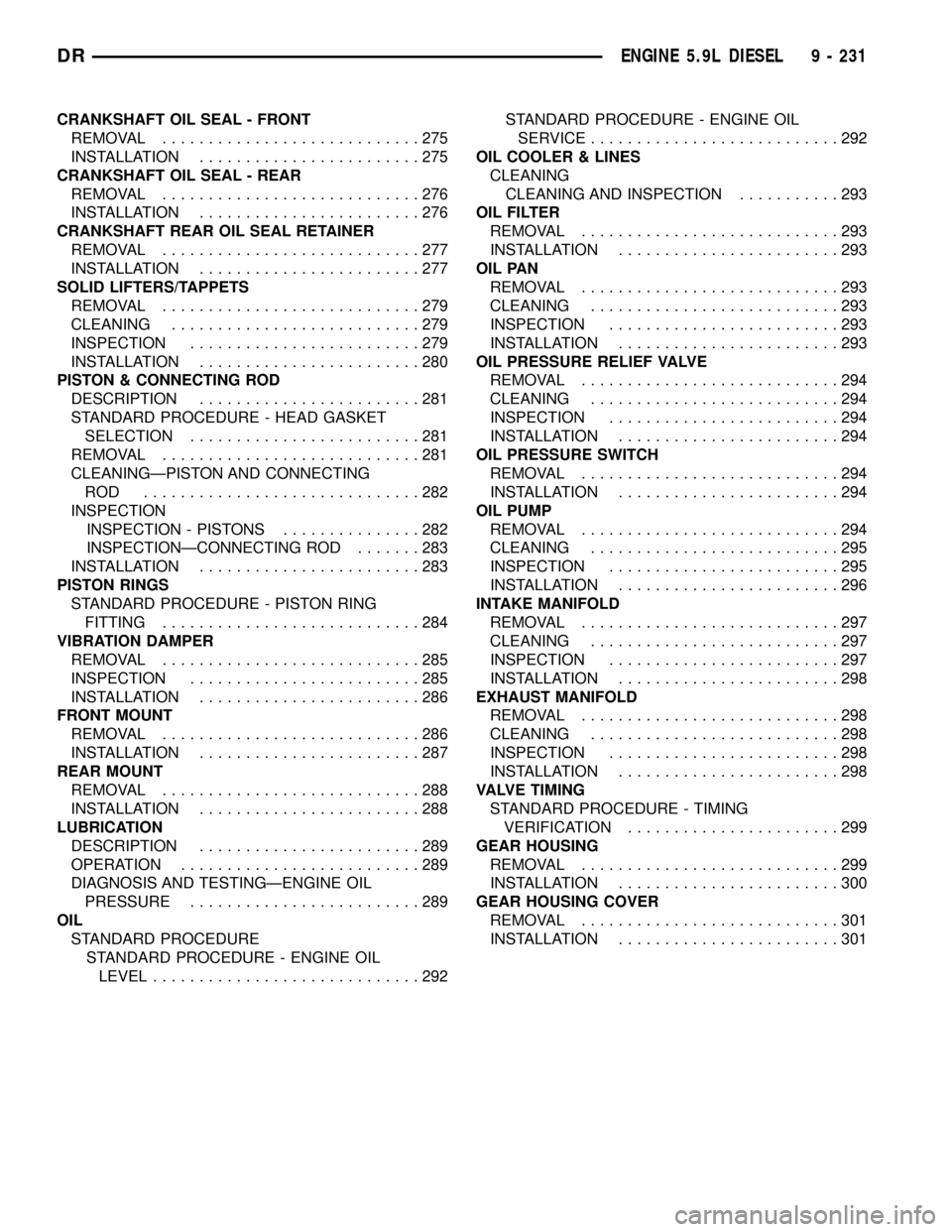
CRANKSHAFT OIL SEAL - FRONT
REMOVAL............................275
INSTALLATION........................275
CRANKSHAFT OIL SEAL - REAR
REMOVAL............................276
INSTALLATION........................276
CRANKSHAFT REAR OIL SEAL RETAINER
REMOVAL............................277
INSTALLATION........................277
SOLID LIFTERS/TAPPETS
REMOVAL............................279
CLEANING...........................279
INSPECTION.........................279
INSTALLATION........................280
PISTON & CONNECTING ROD
DESCRIPTION........................281
STANDARD PROCEDURE - HEAD GASKET
SELECTION.........................281
REMOVAL............................281
CLEANINGÐPISTON AND CONNECTING
ROD ..............................282
INSPECTION
INSPECTION - PISTONS...............282
INSPECTIONÐCONNECTING ROD.......283
INSTALLATION........................283
PISTON RINGS
STANDARD PROCEDURE - PISTON RING
FITTING............................284
VIBRATION DAMPER
REMOVAL............................285
INSPECTION.........................285
INSTALLATION........................286
FRONT MOUNT
REMOVAL............................286
INSTALLATION........................287
REAR MOUNT
REMOVAL............................288
INSTALLATION........................288
LUBRICATION
DESCRIPTION........................289
OPERATION..........................289
DIAGNOSIS AND TESTINGÐENGINE OIL
PRESSURE.........................289
OIL
STANDARD PROCEDURE
STANDARD PROCEDURE - ENGINE OIL
LEVEL.............................292STANDARD PROCEDURE - ENGINE OIL
SERVICE...........................292
OIL COOLER & LINES
CLEANING
CLEANING AND INSPECTION...........293
OIL FILTER
REMOVAL............................293
INSTALLATION........................293
OIL PAN
REMOVAL............................293
CLEANING...........................293
INSPECTION.........................293
INSTALLATION........................293
OIL PRESSURE RELIEF VALVE
REMOVAL............................294
CLEANING...........................294
INSPECTION.........................294
INSTALLATION........................294
OIL PRESSURE SWITCH
REMOVAL............................294
INSTALLATION........................294
OIL PUMP
REMOVAL............................294
CLEANING...........................295
INSPECTION.........................295
INSTALLATION........................296
INTAKE MANIFOLD
REMOVAL............................297
CLEANING...........................297
INSPECTION.........................297
INSTALLATION........................298
EXHAUST MANIFOLD
REMOVAL............................298
CLEANING...........................298
INSPECTION.........................298
INSTALLATION........................298
VALVE TIMING
STANDARD PROCEDURE - TIMING
VERIFICATION.......................299
GEAR HOUSING
REMOVAL............................299
INSTALLATION........................300
GEAR HOUSING COVER
REMOVAL............................301
INSTALLATION........................301
DRENGINE 5.9L DIESEL 9 - 231
Page 1457 of 2627
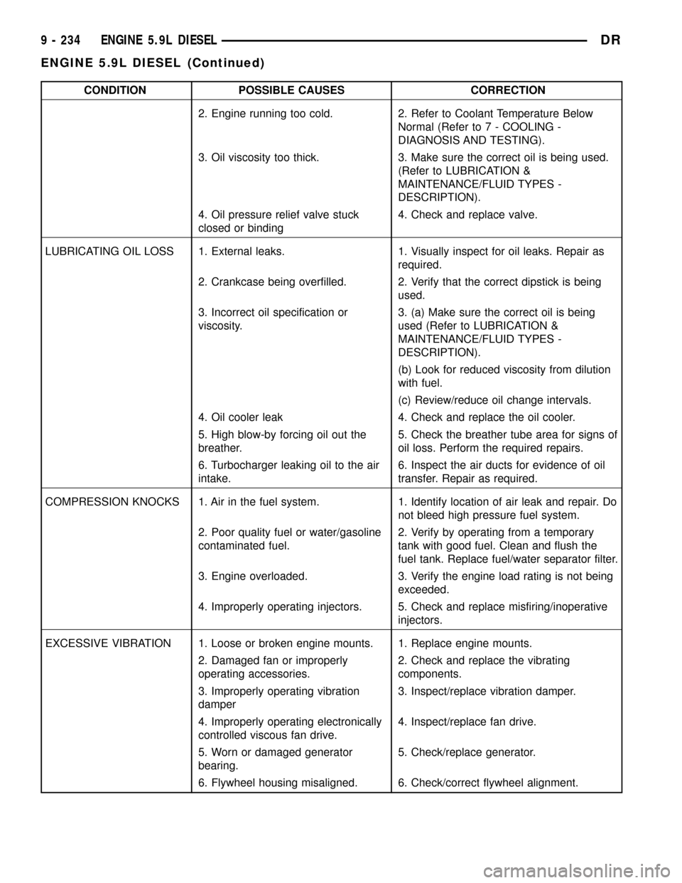
CONDITION POSSIBLE CAUSES CORRECTION
2. Engine running too cold. 2. Refer to Coolant Temperature Below
Normal (Refer to 7 - COOLING -
DIAGNOSIS AND TESTING).
3. Oil viscosity too thick. 3. Make sure the correct oil is being used.
(Refer to LUBRICATION &
MAINTENANCE/FLUID TYPES -
DESCRIPTION).
4. Oil pressure relief valve stuck
closed or binding4. Check and replace valve.
LUBRICATING OIL LOSS 1. External leaks. 1. Visually inspect for oil leaks. Repair as
required.
2. Crankcase being overfilled. 2. Verify that the correct dipstick is being
used.
3. Incorrect oil specification or
viscosity.3. (a) Make sure the correct oil is being
used (Refer to LUBRICATION &
MAINTENANCE/FLUID TYPES -
DESCRIPTION).
(b) Look for reduced viscosity from dilution
with fuel.
(c) Review/reduce oil change intervals.
4. Oil cooler leak 4. Check and replace the oil cooler.
5. High blow-by forcing oil out the
breather.5. Check the breather tube area for signs of
oil loss. Perform the required repairs.
6. Turbocharger leaking oil to the air
intake.6. Inspect the air ducts for evidence of oil
transfer. Repair as required.
COMPRESSION KNOCKS 1. Air in the fuel system. 1. Identify location of air leak and repair. Do
not bleed high pressure fuel system.
2. Poor quality fuel or water/gasoline
contaminated fuel.2. Verify by operating from a temporary
tank with good fuel. Clean and flush the
fuel tank. Replace fuel/water separator filter.
3. Engine overloaded. 3. Verify the engine load rating is not being
exceeded.
4. Improperly operating injectors. 5. Check and replace misfiring/inoperative
injectors.
EXCESSIVE VIBRATION 1. Loose or broken engine mounts. 1. Replace engine mounts.
2. Damaged fan or improperly
operating accessories.2. Check and replace the vibrating
components.
3. Improperly operating vibration
damper3. Inspect/replace vibration damper.
4. Improperly operating electronically
controlled viscous fan drive.4. Inspect/replace fan drive.
5. Worn or damaged generator
bearing.5. Check/replace generator.
6. Flywheel housing misaligned. 6. Check/correct flywheel alignment.
9 - 234 ENGINE 5.9L DIESELDR
ENGINE 5.9L DIESEL (Continued)
Page 1458 of 2627
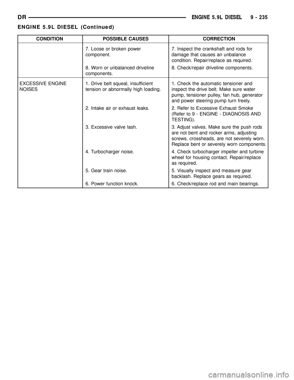
CONDITION POSSIBLE CAUSES CORRECTION
7. Loose or broken power
component.7. Inspect the crankshaft and rods for
damage that causes an unbalance
condition. Repair/replace as required.
8. Worn or unbalanced driveline
components.8. Check/repair driveline components.
EXCESSIVE ENGINE
NOISES1. Drive belt squeal, insufficient
tension or abnormally high loading.1. Check the automatic tensioner and
inspect the drive belt. Make sure water
pump, tensioner pulley, fan hub, generator
and power steering pump turn freely.
2. Intake air or exhaust leaks. 2. Refer to Excessive Exhaust Smoke
(Refer to 9 - ENGINE - DIAGNOSIS AND
TESTING).
3. Excessive valve lash. 3. Adjust valves. Make sure the push rods
are not bent and rocker arms, adjusting
screws, crossheads, are not severely worn.
Replace bent or severely worn components.
4. Turbocharger noise. 4. Check turbocharger impeller and turbine
wheel for housing contact. Repair/replace
as required.
5. Gear train noise. 5. Visually inspect and measure gear
backlash. Replace gears as required.
6. Power function knock. 6. Check/replace rod and main bearings.
DRENGINE 5.9L DIESEL 9 - 235
ENGINE 5.9L DIESEL (Continued)
Page 1461 of 2627
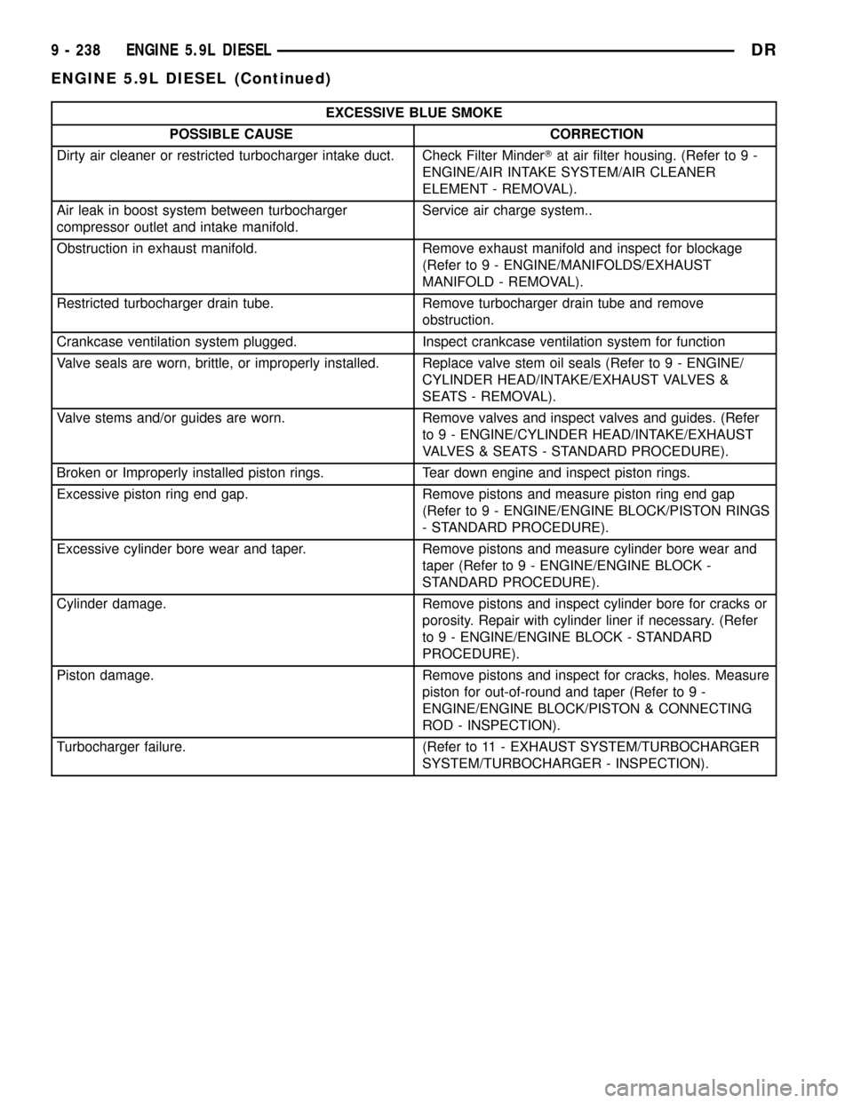
EXCESSIVE BLUE SMOKE
POSSIBLE CAUSE CORRECTION
Dirty air cleaner or restricted turbocharger intake duct. Check Filter MinderTat air filter housing. (Refer to 9 -
ENGINE/AIR INTAKE SYSTEM/AIR CLEANER
ELEMENT - REMOVAL).
Air leak in boost system between turbocharger
compressor outlet and intake manifold.Service air charge system..
Obstruction in exhaust manifold. Remove exhaust manifold and inspect for blockage
(Refer to 9 - ENGINE/MANIFOLDS/EXHAUST
MANIFOLD - REMOVAL).
Restricted turbocharger drain tube. Remove turbocharger drain tube and remove
obstruction.
Crankcase ventilation system plugged. Inspect crankcase ventilation system for function
Valve seals are worn, brittle, or improperly installed. Replace valve stem oil seals (Refer to 9 - ENGINE/
CYLINDER HEAD/INTAKE/EXHAUST VALVES &
SEATS - REMOVAL).
Valve stems and/or guides are worn. Remove valves and inspect valves and guides. (Refer
to 9 - ENGINE/CYLINDER HEAD/INTAKE/EXHAUST
VALVES & SEATS - STANDARD PROCEDURE).
Broken or Improperly installed piston rings. Tear down engine and inspect piston rings.
Excessive piston ring end gap. Remove pistons and measure piston ring end gap
(Refer to 9 - ENGINE/ENGINE BLOCK/PISTON RINGS
- STANDARD PROCEDURE).
Excessive cylinder bore wear and taper. Remove pistons and measure cylinder bore wear and
taper (Refer to 9 - ENGINE/ENGINE BLOCK -
STANDARD PROCEDURE).
Cylinder damage. Remove pistons and inspect cylinder bore for cracks or
porosity. Repair with cylinder liner if necessary. (Refer
to 9 - ENGINE/ENGINE BLOCK - STANDARD
PROCEDURE).
Piston damage. Remove pistons and inspect for cracks, holes. Measure
piston for out-of-round and taper (Refer to 9 -
ENGINE/ENGINE BLOCK/PISTON & CONNECTING
ROD - INSPECTION).
Turbocharger failure. (Refer to 11 - EXHAUST SYSTEM/TURBOCHARGER
SYSTEM/TURBOCHARGER - INSPECTION).
9 - 238 ENGINE 5.9L DIESELDR
ENGINE 5.9L DIESEL (Continued)