1998 DODGE RAM 1500 Oil pan gasket
[x] Cancel search: Oil pan gasketPage 155 of 2627

(4) Align hole in the pinion gears with hole in the
differential case.
(5) Install pinion shaft.
(6) Installnewpinion shaft lock bolt and tighten
to 52 N´m (38 ft. lbs.).
INSTALLATION
(1) Clean the housing cavity with a flushing oil,
light engine oil or lint free cloth.
CAUTION: Do not use water, steam, kerosene or
gasoline for cleaning.
(2) Lubricate differential case bearing.
(3) Install differential case with bearings cups into
the housing.
(4) Install bearing caps and bolts (Fig. 41). Tighten
the bearing cap bolts finger-tight.
NOTE: Do not torque bearing cap and bolts at this
time.
(5) Slide differential case toward the pinion gear
until the gears make contact/zero backlash. If zero
backlash cannot be obtained, turn the pinion side
adjuster until zero backlash is obtained.
(6) Holding the differential case toward the pinion
gear, turn bearing adjusters with Spanner Wrench
8883 until they make contact with the differential
bearings/cups.(7) Back off the ring gear side adjuster 4 holes, to
obtain initial ring gear backlash.
(8) Install ring gear side adjuster lock and bolt. Do
not tighten adjuster lock bolt at this time.
(9) Tighten pinion gear side adjuster firmly
against the differential case bearing cup.
(10) Rotate the pinion several times to seat the dif-
ferential bearings.
(11) Loosen pinion gear side adjuster until it is no
longer in contact with the bearing cup.
(12) Tighten pinion gear side adjuster until it just
makes contact with the bearing cup.
(13) Tighten pinion gear side adjuster an addi-
tional:
²New Bearings:6 Adjuster Holes
²Original Bearings:4 Adjuster Holes
(14) Install pinion gear side adjuster lock and bolt.
Do not tighten adjuster lock bolt at this time.
(15) Tighten bearing cap bolts to 85 N´m (63 ft.
lbs.).
(16) Tighten adjuster lock bolts to 25 N´m (18 ft.
lbs.) (Fig. 42).
(17) Measure ring gear backlash and check gear
tooth contact pattern. Refer to Adjustments for pro-
cedure.
(18) Install axle shafts and hub bearings.
(19) Install differential housing gasket and cover.
Tighten cover bolts to 40 N´m (30 ft. lbs.).
Fig. 41 CASE BEARING CAP
1 - DIFFERENTIAL HOUSING
2 - BEARING CAP
3 - ADJUSTERFig. 42 ADJUSTER LOCK BOLT
1 - DIFFERENTIAL CASE
2 - ADJUSTER LOCK
3 - ADJUSTER LOCK BOLT
4 - BEARING CAP BOLT
3 - 74 FRONT AXLE - 9 1/4 AADR
DIFFERENTIAL (Continued)
Page 211 of 2627

INSTALLATION
(1) Clean the housing cavity with a flushing oil,
light engine oil or lint free cloth.
CAUTION: Do not use water, steam, kerosene or
gasoline for cleaning.
(2) Lubricate differential case bearing.
(3) Install differential case with bearings cups into
the housing.
NOTE: A light coat of grease on the cups will hold
them in place during installation.
(4) Install bearing caps and bolts (Fig. 36). Tighten
the bearing cap bolts finger-tight.
NOTE: Do not torque bearing cap and bolts at this
time.
(5) Slide differential case toward the pinion gear
until the gears make contact/zero backlash. If zero
backlash cannot be obtained, turn the pinion side
adjuster until zero backlash is obtained.
(6) Holding the differential case toward the pinion
gear, turn bearing adjusters with Spanner Wrench
8883 until they make contact with the differential
bearings/cups.
(7) Back off the ring gear side adjuster 4 holes, to
obtain initial ring gear backlash.
(8) Install ring gear side adjuster lock and bolt. Do
not tighten adjuster lock bolt at this time.(9) Tighten pinion gear side adjuster firmly
against the differential case bearing cup.
(10) Rotate the pinion several times to seat the dif-
ferential bearings.
(11) Loosen pinion gear side adjuster until it is no
longer in contact with the bearing cup.
(12) Tighten pinion gear side adjuster until it just
makes contact with the bearing cup.
(13) Tighten pinion gear side adjuster an addi-
tional:
²New Bearings6 Adjuster Holes
²Original Bearings4 Adjuster Holes
(14) Install pinion gear side adjuster lock and bolt.
Do not tighten adjuster lock bolt at this time.
(15) Tighten bearing cap bolts to 165 N´m (122 ft.
lbs.).
(16) Tighten adjuster lock bolts to 25 N´m (18 ft.
lbs.) (Fig. 37).
(17) Measure ring gear backlash and check gear
tooth contact pattern. Refer to Adjustments for pro-
cedure.
(18) Install axle shafts.
(19) Install differential housing gasket and cover.
Tighten cover bolts to 40 N´m (30 ft. lbs.).
(20) Fill axle with lubricant, refer to Lubrication &
Maintenance for capacity and lubricant type.
(21) Install fill plug and tighten to 32 N´m (24 ft.
lbs.).
Fig. 36 CASE BEARING CAP
1 - DIFFERENTIAL HOUSING
2 - BEARING CAP
3 - ADJUSTERFig. 37 ADJUSTER LOCK BOLT
1 - DIFFERENTIAL CASE
2 - ADJUSTER LOCK
3 - ADJUSTER LOCK BOLT
4 - BEARING CAP BOLT
3 - 130 REAR AXLE - 10 1/2 AADR
DIFFERENTIAL (Continued)
Page 321 of 2627

PRESSURE TESTER METHOD
The engine should be at normal operating temper-
ature. Recheck the system cold if the cause of coolant
loss is not located during the warm engine examina-
tion.
WARNING: HOT, PRESSURIZED COOLANT CAN
CAUSE INJURY BY SCALDING.
Carefully remove the radiator pressure cap from
the filler neck and check the coolant level. Push
down on the cap to disengage it from the stop tabs.
Wipe the inside of the filler neck and examine the
lower inside sealing seat for nicks, cracks, paint, dirt
and solder residue. Inspect the radiator-to- reserve/
overflow tank hose for internal obstructions. Insert a
wire through the hose to be sure it is not obstructed.
Inspect the cams on the outside of the filler neck.
If the cams are damaged, seating of the pressure cap
valve and tester seal will be affected.
Attach pressure tester (7700 or an equivalent) to
radiator filler neck.
Operate the tester pump to apply 103.4 kPa (15
psi) pressure to the system. If the hoses enlarge
excessively or bulges while testing, replace as neces-
sary. Observe the gauge pointer and determine the
condition of the cooling system according to following
criteria:
Holds Steady:If the pointer remains steady for
two minutes, serious coolant leaks are not present in
system. However, there could be an internal leakthat does not appear with normal system test pres-
sure. If it is certain that coolant is being lost and
leaks cannot be detected, inspect for interior leakage
or perform Internal Leakage Test. Refer to INTER-
NAL LEAKAGE INSPECTION.
Drops Slowly:Indicates a small leak or seepage
is occurring. Examine all of the connections for seep-
age or slight leakage with a flashlight. Inspect the
radiator, hoses, gasket edges and heater. Seal the
small leak holes with a Sealer Lubricant (or equiva-
lent). Repair the leak holes and inspect the system
again with pressure applied.
Drops Quickly:Indicates that serious leakage is
occurring. Examine the system for external leakage.
If leaks are not visible, inspect for internal leakage.
Large radiator leak holes should be repaired by a
reputable radiator repair shop.
INTERNAL LEAKAGE INSPECTION
Remove the engine oil pan drain plug and drain a
small amount of engine oil. If coolant is present in
the pan, it will drain first because it is heavier than
oil. An alternative method is to operate engine for a
short period to churn the oil. After this is done,
remove the engine dipstick and inspect for water
globules. Also inspect the transmission dipstick for
water globules and transmission fluid cooler for leak-
age.
WARNING: WITH RADIATOR PRESSURE TESTER
TOOL INSTALLED ON RADIATOR, DO NOT ALLOW
PRESSURE TO EXCEED 145 kPa (21 PSI). PRES-
SURE WILL BUILD UP QUICKLY IF A COMBUSTION
LEAK IS PRESENT. TO RELEASE PRESSURE,
ROCK TESTER FROM SIDE TO SIDE. WHEN
REMOVING TESTER, DO NOT TURN TESTER MORE
THAN 1/2 TURN IF SYSTEM IS UNDER PRESSURE.
Operate the engine without the pressure cap on
the radiator until the thermostat opens. Attach a
Pressure Tester to the filler neck. If pressure builds
up quickly it indicates a combustion leak exists. This
is usually the result of a cylinder head gasket leak or
crack in engine. Repair as necessary.
If there is not an immediate pressure increase,
pump the Pressure Tester. Do this until indicated
pressure is within system range of 110 kPa (16 psi).
Fluctuation of the gauge pointer indicates compres-
sion or combustion leakage into cooling system.
Because the vehicle is equipped with a catalytic
converter,do notshort out cylinders to isolate com-
pression leak.
If the needle on dial of the pressure tester does not
fluctuate, race engine a few times to check for an
abnormal amount of coolant or steam. This would be
emitting from exhaust pipe. Coolant or steam from
Fig. 5 Leak Detection Using Black Light - Typical
1 - TYPICAL BLACK LIGHT TOOL
7 - 6 COOLINGDR
COOLING (Continued)
Page 1230 of 2627
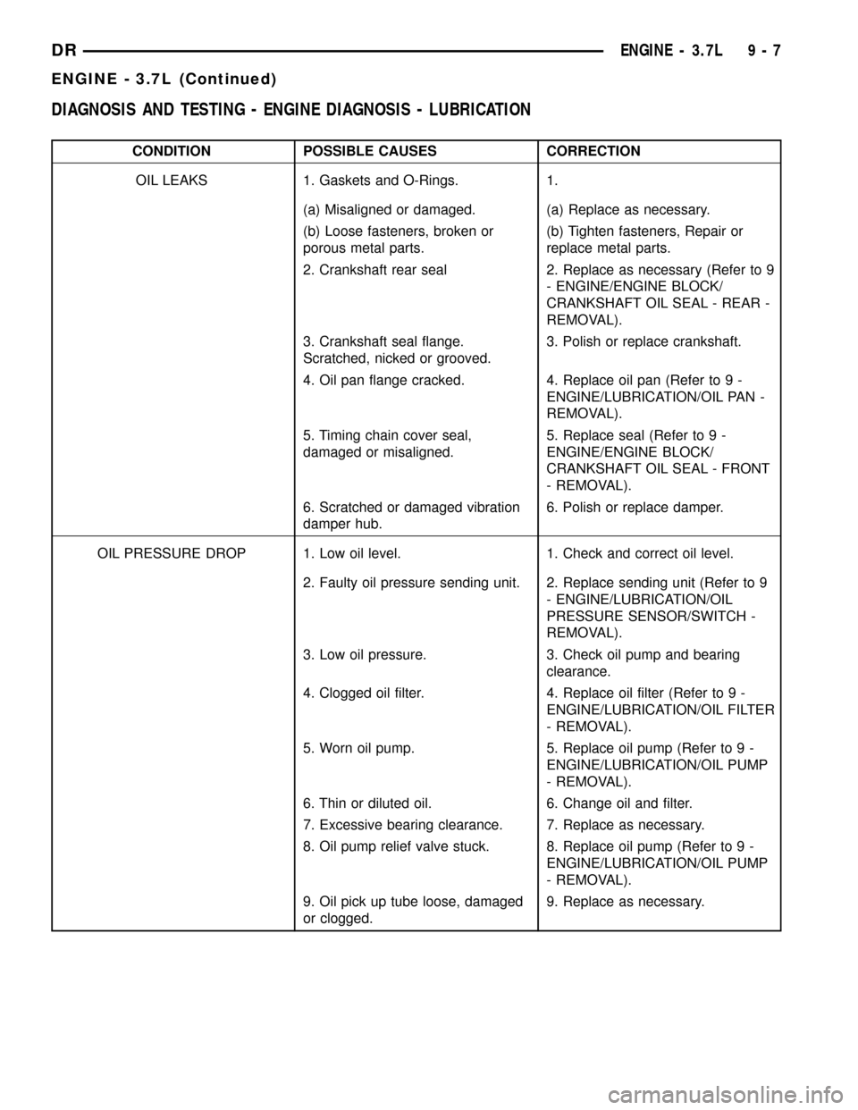
DIAGNOSIS AND TESTING - ENGINE DIAGNOSIS - LUBRICATION
CONDITION POSSIBLE CAUSES CORRECTION
OIL LEAKS 1. Gaskets and O-Rings. 1.
(a) Misaligned or damaged. (a) Replace as necessary.
(b) Loose fasteners, broken or
porous metal parts.(b) Tighten fasteners, Repair or
replace metal parts.
2. Crankshaft rear seal 2. Replace as necessary (Refer to 9
- ENGINE/ENGINE BLOCK/
CRANKSHAFT OIL SEAL - REAR -
REMOVAL).
3. Crankshaft seal flange.
Scratched, nicked or grooved.3. Polish or replace crankshaft.
4. Oil pan flange cracked. 4. Replace oil pan (Refer to 9 -
ENGINE/LUBRICATION/OIL PAN -
REMOVAL).
5. Timing chain cover seal,
damaged or misaligned.5. Replace seal (Refer to 9 -
ENGINE/ENGINE BLOCK/
CRANKSHAFT OIL SEAL - FRONT
- REMOVAL).
6. Scratched or damaged vibration
damper hub.6. Polish or replace damper.
OIL PRESSURE DROP 1. Low oil level. 1. Check and correct oil level.
2. Faulty oil pressure sending unit. 2. Replace sending unit (Refer to 9
- ENGINE/LUBRICATION/OIL
PRESSURE SENSOR/SWITCH -
REMOVAL).
3. Low oil pressure. 3. Check oil pump and bearing
clearance.
4. Clogged oil filter. 4. Replace oil filter (Refer to 9 -
ENGINE/LUBRICATION/OIL FILTER
- REMOVAL).
5. Worn oil pump. 5. Replace oil pump (Refer to 9 -
ENGINE/LUBRICATION/OIL PUMP
- REMOVAL).
6. Thin or diluted oil. 6. Change oil and filter.
7. Excessive bearing clearance. 7. Replace as necessary.
8. Oil pump relief valve stuck. 8. Replace oil pump (Refer to 9 -
ENGINE/LUBRICATION/OIL PUMP
- REMOVAL).
9. Oil pick up tube loose, damaged
or clogged.9. Replace as necessary.
DRENGINE - 3.7L 9 - 7
ENGINE - 3.7L (Continued)
Page 1263 of 2627
(2) Measure the inside diameter of the cylinder
bore at three levels below top of bore. Start perpen-
dicular (across or at 90 degrees) to the axis of the
crankshaft and then take two additional reading.
(3) Measure the cylinder bore diameter crosswise
to the cylinder block near the top of the bore. Repeat
the measurement near the middle of the bore, then
repeat the measurement near the bottom of the bore.
(4) Determine taper by subtracting the smaller
diameter from the larger diameter.
(5) Rotate measuring device 90É and repeat steps
above.
(6) Determine out-of-roundness by comparing the
difference between each measurement.
(7) If cylinder bore taper does not exceed 0.025
mm (0.001 inch) and out-of-roundness does not
exceed 0.025 mm (0.001 inch), the cylinder bore can
be honed. If the cylinder bore taper or out- of-round
condition exceeds these maximum limits, the cylinder
block must be replaced. A slight amount of taper
always exists in the cylinder bore after the engine
has been in use for a period of time.
CRANKSHAFT
DESCRIPTION
The crankshaft is constructed of nodular cast iron.
The crankshaft is a three throw split pin design with
six counterweights for balancing purposes. The
crankshaft is supported by four select fit main bear-
ings with the No. 2 serving as the thrust washer
location. The main journals of the crankshaft are
cross drilled to improve rod bearing lubrication. The
No. 6 counterweight has provisions for crankshaft
position sensor target wheel mounting. The select fit
main bearing markings are located on the rear side
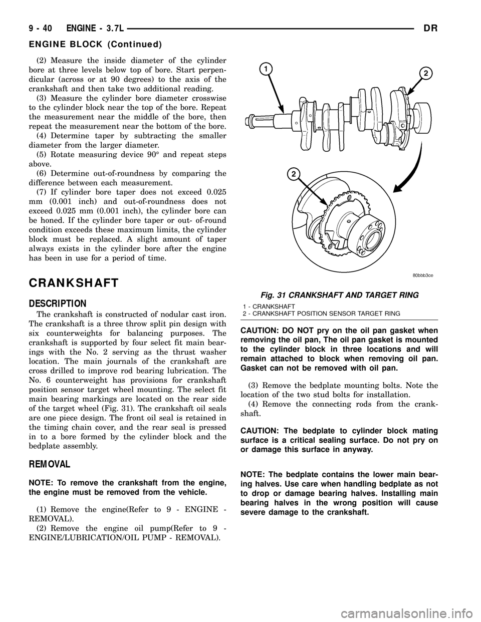
of the target wheel (Fig. 31). The crankshaft oil seals
are one piece design. The front oil seal is retained in
the timing chain cover, and the rear seal is pressed
in to a bore formed by the cylinder block and the
bedplate assembly.
REMOVAL
NOTE: To remove the crankshaft from the engine,
the engine must be removed from the vehicle.
(1) Remove the engine(Refer to 9 - ENGINE -
REMOVAL).
(2) Remove the engine oil pump(Refer to 9 -
ENGINE/LUBRICATION/OIL PUMP - REMOVAL).CAUTION: DO NOT pry on the oil pan gasket when
removing the oil pan, The oil pan gasket is mounted
to the cylinder block in three locations and will
remain attached to block when removing oil pan.
Gasket can not be removed with oil pan.
(3) Remove the bedplate mounting bolts. Note the
location of the two stud bolts for installation.
(4) Remove the connecting rods from the crank-
shaft.
CAUTION: The bedplate to cylinder block mating
surface is a critical sealing surface. Do not pry on
or damage this surface in anyway.
NOTE: The bedplate contains the lower main bear-
ing halves. Use care when handling bedplate as not
to drop or damage bearing halves. Installing main
bearing halves in the wrong position will cause
severe damage to the crankshaft.
Fig. 31 CRANKSHAFT AND TARGET RING
1 - CRANKSHAFT
2 - CRANKSHAFT POSITION SENSOR TARGET RING
9 - 40 ENGINE - 3.7LDR
ENGINE BLOCK (Continued)
Page 1264 of 2627
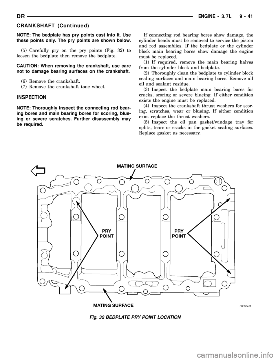
NOTE: The bedplate has pry points cast into it. Use
these points only. The pry points are shown below.
(5) Carefully pry on the pry points (Fig. 32) to
loosen the bedplate then remove the bedplate.
CAUTION: When removing the crankshaft, use care
not to damage bearing surfaces on the crankshaft.
(6) Remove the crankshaft.
(7) Remove the crankshaft tone wheel.
INSPECTION
NOTE: Thoroughly inspect the connecting rod bear-
ing bores and main bearing bores for scoring, blue-
ing or severe scratches. Further disassembly may
be required.If connecting rod bearing bores show damage, the
cylinder heads must be removed to service the piston
and rod assemblies. If the bedplate or the cylinder
block main bearing bores show damage the engine
must be replaced.
(1) If required, remove the main bearing halves
from the cylinder block and bedplate.
(2) Thoroughly clean the bedplate to cylinder block
sealing surfaces and main bearing bores. Remove all
oil and sealant residue.
(3) Inspect the bedplate main bearing bores for
cracks, scoring or severe blueing. If either condition
exists the engine must be replaced.
(4) Inspect the crankshaft thrust washers for scor-
ing, scratches, wear or blueing. If either condition
exist replace the thrust washers.
(5) Inspect the oil pan gasket/windage tray for
splits, tears or cracks in the gasket sealing surfaces.
Replace gasket as necessary.
Fig. 32 BEDPLATE PRY POINT LOCATION
DRENGINE - 3.7L 9 - 41
CRANKSHAFT (Continued)
Page 1274 of 2627
(10) Once you have selected the proper insert,
install the insert and cap. Tighten the connecting rod
bolts to 27 N´m (20 ft. lbs.) plus a 90É turn.
Slide snug-fitting feeler gauge between the con-
necting rod and crankshaft journal flange (Fig. 50).
Refer to Engine Specifications for the proper clear-
ance. Replace the connecting rod if the side clearance
is not within specification.
STANDARD PROCEDURE - PISTON FITTING
(1) To correctly select the proper size piston, a cyl-
inder bore gauge, capable of reading in 0.003 mm (
.0001 in.) INCREMENTS is required. If a bore gauge
is not available, do not use an inside micrometer.
(2) Measure the inside diameter of the cylinder
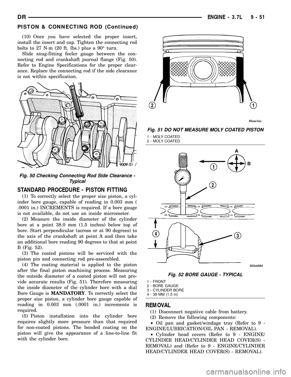
bore at a point 38.0 mm (1.5 inches) below top of
bore. Start perpendicular (across or at 90 degrees) to
the axis of the crankshaft at point A and then take
an additional bore reading 90 degrees to that at point
B (Fig. 52).
(3) The coated pistons will be serviced with the
piston pin and connecting rod pre-assembled.
(4) The coating material is applied to the piston
after the final piston machining process. Measuring
the outside diameter of a coated piston will not pro-
vide accurate results (Fig. 51). Therefore measuring
the inside diameter of the cylinder bore with a dial
Bore Gauge isMANDATORY. To correctly select the
proper size piston, a cylinder bore gauge capable of
reading in 0.003 mm (.0001 in.) increments is
required.
(5) Piston installation into the cylinder bore
requires slightly more pressure than that required
for non-coated pistons. The bonded coating on the
piston will give the appearance of a line-to-line fit
with the cylinder bore.
REMOVAL
(1) Disconnect negative cable from battery.
(2) Remove the following components:
²Oil pan and gasket/windage tray (Refer to 9 -
ENGINE/LUBRICATION/OIL PAN - REMOVAL).
²Cylinder head covers (Refer to 9 - ENGINE/
CYLINDER HEAD/CYLINDER HEAD COVER(S) -
REMOVAL) and (Refer to 9 - ENGINE/CYLINDER
HEAD/CYLINDER HEAD COVER(S) - REMOVAL).
Fig. 50 Checking Connecting Rod Side Clearance -
Typical
Fig. 51 DO NOT MEASURE MOLY COATED PISTON
1 - MOLY COATED
2 - MOLY COATED
Fig. 52 BORE GAUGE - TYPICAL
1 - FRONT
2 - BORE GAUGE
3 - CYLINDER BORE
4 - 38 MM (1.5 in)
DRENGINE - 3.7L 9 - 51
PISTON & CONNECTING ROD (Continued)
Page 1276 of 2627
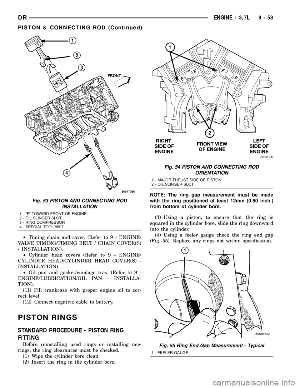
²Timing chain and cover. (Refer to 9 - ENGINE/
VALVE TIMING/TIMING BELT / CHAIN COVER(S)
- INSTALLATION).
²Cylinder head covers (Refer to 9 - ENGINE/
CYLINDER HEAD/CYLINDER HEAD COVER(S) -
INSTALLATION).
²Oil pan and gasket/windage tray. (Refer to 9 -
ENGINE/LUBRICATION/OIL PAN - INSTALLA-
TION).
(11) Fill crankcase with proper engine oil to cor-
rect level.
(12) Connect negative cable to battery.
PISTON RINGS
STANDARD PROCEDURE - PISTON RING
FITTING
Before reinstalling used rings or installing new
rings, the ring clearances must be checked.
(1) Wipe the cylinder bore clean.
(2) Insert the ring in the cylinder bore.NOTE: The ring gap measurement must be made
with the ring positioned at least 12mm (0.50 inch.)
from bottom of cylinder bore.
(3) Using a piston, to ensure that the ring is
squared in the cylinder bore, slide the ring downward
into the cylinder.
(4) Using a feeler gauge check the ring end gap
(Fig. 55). Replace any rings not within specification.
Fig. 53 PISTON AND CONNECTING ROD
INSTALLATION
1 - ªFº TOWARD FRONT OF ENGINE
2 - OIL SLINGER SLOT
3 - RING COMPRESSOR
4 - SPECIAL TOOL 8507
Fig. 54 PISTON AND CONNECTING ROD
ORIENTATION
1 - MAJOR THRUST SIDE OF PISTON
2 - OIL SLINGER SLOT
Fig. 55 Ring End Gap Measurement - Typical
1 - FEELER GAUGE
DRENGINE - 3.7L 9 - 53
PISTON & CONNECTING ROD (Continued)