Page 1412 of 2627
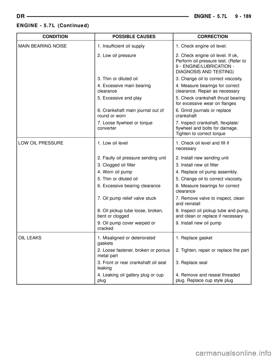
CONDITION POSSIBLE CAUSES CORRECTION
MAIN BEARING NOISE 1. Insufficient oil supply 1. Check engine oil level.
2. Low oil pressure 2. Check engine oil level. If ok,
Perform oil pressure test. (Refer to
9 - ENGINE/LUBRICATION -
DIAGNOSIS AND TESTING)
3. Thin or diluted oil 3. Change oil to correct viscosity.
4. Excessive main bearing
clearance4. Measure bearings for correct
clearance. Repair as necessary
5. Excessive end play 5. Check crankshaft thrust bearing
for excessive wear on flanges
6. Crankshaft main journal out of
round or worn6. Grind journals or replace
crankshaft
7. Loose flywheel or torque
converter7. Inspect crankshaft, flexplate/
flywheel and bolts for damage.
Tighten to correct torque
LOW OIL PRESSURE 1. Low oil level 1. Check oil level and fill if
necessary
2. Faulty oil pressure sending unit 2. Install new sending unit
3. Clogged oil filter 3. Install new oil filter
4. Worn oil pump 4. Replace oil pump assembly.
5. Thin or diluted oil 5. Change oil to correct viscosity.
6. Excessive bearing clearance 6. Measure bearings for correct
clearance
7. Oil pump relief valve stuck 7. Remove valve to inspect, clean
and reinstall
8. Oil pickup tube loose, broken,
bent or clogged8. Inspect oil pickup tube and pump,
and clean or replace if necessary
9. Oil pump cover warped or
cracked9. Install new oil pump
OIL LEAKS 1. Misaligned or deteriorated
gaskets1. Replace gasket
2. Loose fastener, broken or porous
metal part2. Tighten, repair or replace the part
3. Front or rear crankshaft oil seal
leaking3. Replace seal
4. Leaking oil gallery plug or cup
plug4. Remove and reseal threaded
plug. Replace cup style plug
DRENGINE - 5.7L 9 - 189
ENGINE - 5.7L (Continued)
Page 1413 of 2627
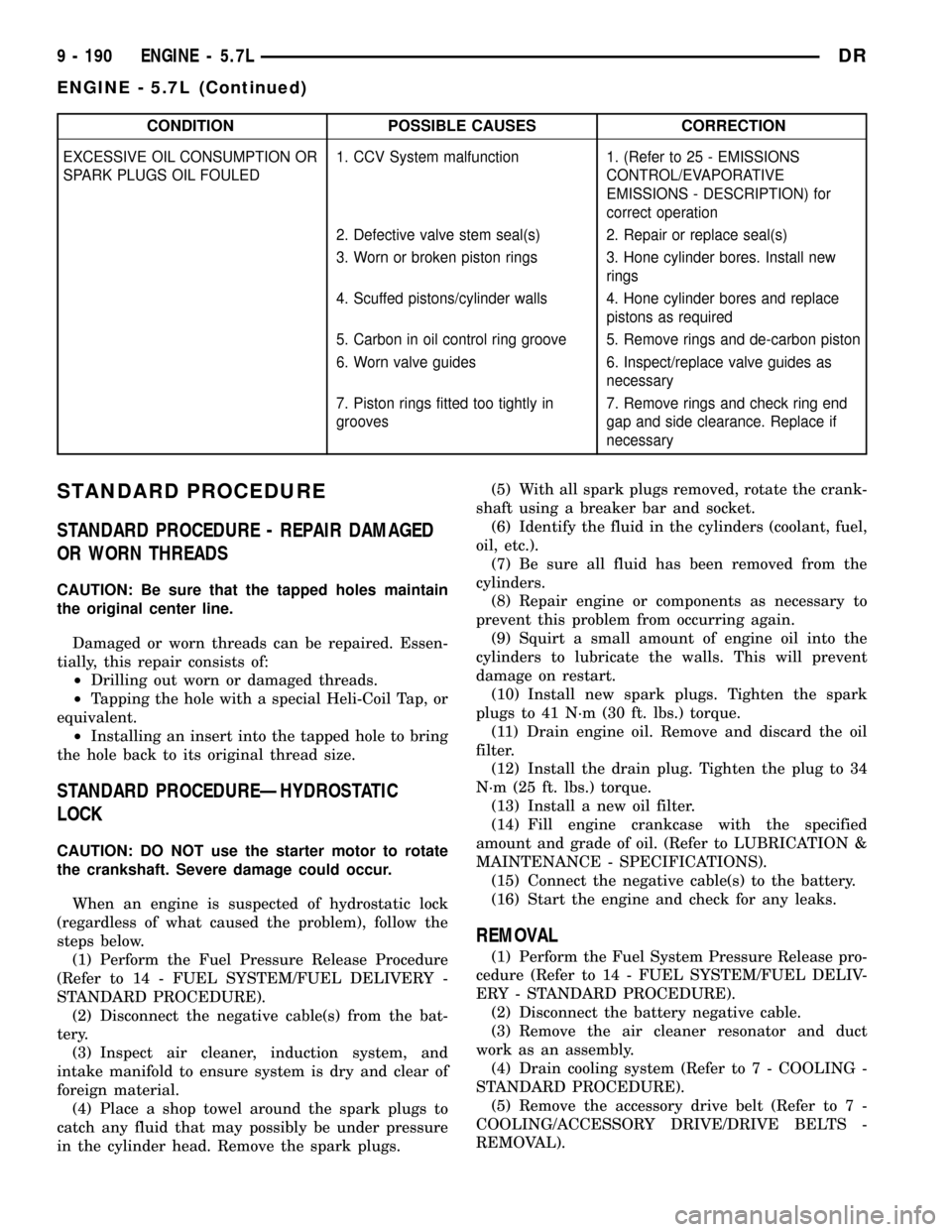
CONDITION POSSIBLE CAUSES CORRECTION
EXCESSIVE OIL CONSUMPTION OR
SPARK PLUGS OIL FOULED1. CCV System malfunction 1. (Refer to 25 - EMISSIONS
CONTROL/EVAPORATIVE
EMISSIONS - DESCRIPTION) for
correct operation
2. Defective valve stem seal(s) 2. Repair or replace seal(s)
3. Worn or broken piston rings 3. Hone cylinder bores. Install new
rings
4. Scuffed pistons/cylinder walls 4. Hone cylinder bores and replace
pistons as required
5. Carbon in oil control ring groove 5. Remove rings and de-carbon piston
6. Worn valve guides 6. Inspect/replace valve guides as
necessary
7. Piston rings fitted too tightly in
grooves7. Remove rings and check ring end
gap and side clearance. Replace if
necessary
STANDARD PROCEDURE
STANDARD PROCEDURE - REPAIR DAMAGED
OR WORN THREADS
CAUTION: Be sure that the tapped holes maintain
the original center line.
Damaged or worn threads can be repaired. Essen-
tially, this repair consists of:
²Drilling out worn or damaged threads.
²Tapping the hole with a special Heli-Coil Tap, or
equivalent.
²Installing an insert into the tapped hole to bring
the hole back to its original thread size.
STANDARD PROCEDUREÐHYDROSTATIC
LOCK
CAUTION: DO NOT use the starter motor to rotate
the crankshaft. Severe damage could occur.
When an engine is suspected of hydrostatic lock
(regardless of what caused the problem), follow the
steps below.
(1) Perform the Fuel Pressure Release Procedure
(Refer to 14 - FUEL SYSTEM/FUEL DELIVERY -
STANDARD PROCEDURE).
(2) Disconnect the negative cable(s) from the bat-
tery.
(3) Inspect air cleaner, induction system, and
intake manifold to ensure system is dry and clear of
foreign material.
(4) Place a shop towel around the spark plugs to
catch any fluid that may possibly be under pressure
in the cylinder head. Remove the spark plugs.(5) With all spark plugs removed, rotate the crank-
shaft using a breaker bar and socket.
(6) Identify the fluid in the cylinders (coolant, fuel,
oil, etc.).
(7) Be sure all fluid has been removed from the
cylinders.
(8) Repair engine or components as necessary to
prevent this problem from occurring again.
(9) Squirt a small amount of engine oil into the
cylinders to lubricate the walls. This will prevent
damage on restart.
(10) Install new spark plugs. Tighten the spark
plugs to 41 N´m (30 ft. lbs.) torque.
(11) Drain engine oil. Remove and discard the oil
filter.
(12) Install the drain plug. Tighten the plug to 34
N´m (25 ft. lbs.) torque.
(13) Install a new oil filter.
(14) Fill engine crankcase with the specified
amount and grade of oil. (Refer to LUBRICATION &
MAINTENANCE - SPECIFICATIONS).
(15) Connect the negative cable(s) to the battery.
(16) Start the engine and check for any leaks.
REMOVAL
(1) Perform the Fuel System Pressure Release pro-
cedure (Refer to 14 - FUEL SYSTEM/FUEL DELIV-
ERY - STANDARD PROCEDURE).
(2) Disconnect the battery negative cable.
(3) Remove the air cleaner resonator and duct
work as an assembly.
(4) Drain cooling system (Refer to 7 - COOLING -
STANDARD PROCEDURE).
(5) Remove the accessory drive belt (Refer to 7 -
COOLING/ACCESSORY DRIVE/DRIVE BELTS -
REMOVAL).
9 - 190 ENGINE - 5.7LDR
ENGINE - 5.7L (Continued)
Page 1415 of 2627
(31)Install the air cleaner resonator and duct work..
(32) Add engine oil to crankcase (Refer to LUBRI-
CATION & MAINTENANCE/FLUID TYPES - SPEC-
IFICATIONS).
(33) Fill cooling system (Refer to 7 - COOLING -
STANDARD PROCEDURE).
(34) Connect battery negative cable.
(35) Start engine and inspect for leaks.
(36) Road test vehicle.
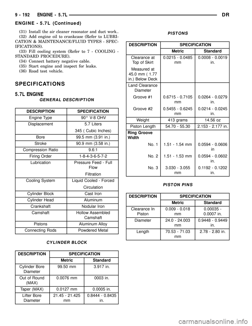
SPECIFICATIONS
5.7L ENGINE
GENERAL DESCRIPTION
DESCRIPTION SPECIFICATION
Engine Type 90É V-8 OHV
Displacement 5.7 Liters
345 ( Cubic Inches)
Bore 99.5 mm (3.91 in.)
Stroke 90.9 mm (3.58 in.)
Compression Ratio 9.6:1
Firing Order 1-8-4-3-6-5-7-2
Lubrication Pressure Feed - Full
Flow
Filtration
Cooling System Liquid Cooled - Forced
Circulation
Cylinder Block Cast Iron
Cylinder Head Aluminum
Crankshaft Nodular Iron
Camshaft Hollow Assembled
Camshaft
Pistons Aluminum Alloy
Connecting Rods Powdered Metal
CYLINDER BLOCK
DESCRIPTION SPECIFICATION
Metric Standard
Cylinder Bore
Diameter99.50 mm 3.917 in.
Out of Round
(MAX)0.0076 mm 0003 in.
Taper (MAX) 0.0127 mm 0.0005 in.
Lifter Bore
Diameter21.45 - 21.425
mm0.8444 - 0.8435
in.
PISTONS
DESCRIPTION SPECIFICATION
Metric Standard
Clearance at
Top of Skirt0.0215 - 0.0485
mm0.0008 - 0.0019
in.
Measured at
45.0 mm ( 1.77
in.) Below Deck
Land Clearance
Diameter
Groove #1 0.6715 - 0.7105
mm0.0264 - 0.0279
in.
Groove #2 0.5455 - 0.6245
mm0.0214 - 0.0245
in.
Weight 413 grams 14.56 oz
Piston Length 54.70 - 55.30 2.153 - 2.177 in.
Ring Groove
Width
No. 1 1.51 - 1.54 mm 0.0594 - 0.0606
in
No. 2 1.51 - 1.53 mm 0.0594 - 0.0602
in.
No. 3 3.030 - 3.055
mm0.1192 - 0.1202
in.
PISTON PINS
DESCRIPTION SPECIFICATION
Metric Standard
Clearance In
Piston0.009 - 0.018
mm0.00035 -
0.0007 in.
Diameter 24.0 - 24.003
mm0.9448 - 0.9449
in.
Length 70.53 - 71.03
mm2.78 - 2.80 in.
9 - 192 ENGINE - 5.7LDR
ENGINE - 5.7L (Continued)
Page 1416 of 2627
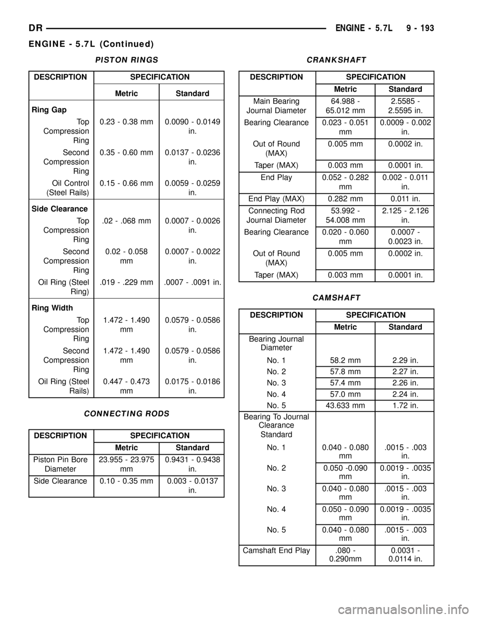
PISTON RINGS
DESCRIPTION SPECIFICATION
Metric Standard
Ring Gap
To p
Compression
Ring0.23 - 0.38 mm 0.0090 - 0.0149
in.
Second
Compression
Ring0.35 - 0.60 mm 0.0137 - 0.0236
in.
Oil Control
(Steel Rails)0.15 - 0.66 mm 0.0059 - 0.0259
in.
Side Clearance
To p
Compression
Ring.02 - .068 mm 0.0007 - 0.0026
in.
Second
Compression
Ring0.02 - 0.058
mm0.0007 - 0.0022
in.
Oil Ring (Steel
Ring).019 - .229 mm .0007 - .0091 in.
Ring Width
To p
Compression
Ring1.472 - 1.490
mm0.0579 - 0.0586
in.
Second
Compression
Ring1.472 - 1.490
mm0.0579 - 0.0586
in.
Oil Ring (Steel
Rails)0.447 - 0.473
mm0.0175 - 0.0186
in.
CONNECTING RODS
DESCRIPTION SPECIFICATION
Metric Standard
Piston Pin Bore
Diameter23.955 - 23.975
mm0.9431 - 0.9438
in.
Side Clearance 0.10 - 0.35 mm 0.003 - 0.0137
in.
CRANKSHAFT
DESCRIPTION SPECIFICATION
Metric Standard
Main Bearing
Journal Diameter64.988 -
65.012 mm2.5585 -
2.5595 in.
Bearing Clearance 0.023 - 0.051
mm0.0009 - 0.002
in.
Out of Round
(MAX)0.005 mm 0.0002 in.
Taper (MAX) 0.003 mm 0.0001 in.
End Play 0.052 - 0.282
mm0.002 - 0.011
in.
End Play (MAX) 0.282 mm 0.011 in.
Connecting Rod
Journal Diameter53.992 -
54.008 mm2.125 - 2.126
in.
Bearing Clearance 0.020 - 0.060
mm0.0007 -
0.0023 in.
Out of Round
(MAX)0.005 mm 0.0002 in.
Taper (MAX) 0.003 mm 0.0001 in.
CAMSHAFT
DESCRIPTION SPECIFICATION
Metric Standard
Bearing Journal
Diameter
No. 1 58.2 mm 2.29 in.
No. 2 57.8 mm 2.27 in.
No. 3 57.4 mm 2.26 in.
No. 4 57.0 mm 2.24 in.
No. 5 43.633 mm 1.72 in.
Bearing To Journal
Clearance
Standard
No. 1 0.040 - 0.080
mm.0015 - .003
in.
No. 2 0.050 -0.090
mm0.0019 - .0035
in.
No. 3 0.040 - 0.080
mm.0015 - .003
in.
No. 4 0.050 - 0.090
mm0.0019 - .0035
in.
No. 5 0.040 - 0.080
mm.0015 - .003
in.
Camshaft End Play .080 -
0.290mm0.0031 -
0.0114 in.
DRENGINE - 5.7L 9 - 193
ENGINE - 5.7L (Continued)
Page 1418 of 2627
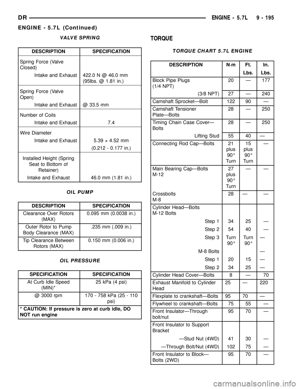
VALVE SPRING
DESCRIPTION SPECIFICATION
Spring Force (Valve
Closed)
Intake and Exhaust 422.0 N @ 46.0 mm
(95lbs. @ 1.81 in.)
Spring Force (Valve
Open)
Intake and Exhaust @ 33.5 mm
Number of Coils
Intake and Exhaust 7.4
Wire Diameter
Intake and Exhaust 5.39 ý 4.52 mm
(0.212 - 0.177 in.)
Installed Height (Spring
Seat to Bottom of
Retainer)
Intake and Exhaust 46.0 mm (1.81 in.)
OIL PUMP
DESCRIPTION SPECIFICATION
Clearance Over Rotors
(MAX)0.095 mm (0.0038 in.)
Outer Rotor to Pump
Body Clearance (MAX).235 mm (.009 in.)
Tip Clearance Between
Rotors (MAX)0.150 mm (0.006 in.)
OIL PRESSURE
SPECIFICATION SPECIFICATION
At Curb Idle Speed
(MIN)*25 kPa (4 psi)
@ 3000 rpm 170 - 758 kPa (25 - 110
psi)
* CAUTION: If pressure is zero at curb idle, DO
NOT run engine
TORQUE
TORQUE CHART 5.7L ENGINE
DESCRIPTION N´m Ft. In.
Lbs. Lbs.
Block Pipe Plugs
(1/4 NPT)20 Ð 177
(3/8 NPT) 27 Ð 240
Camshaft SprocketÐBolt 122 90 Ð
Camshaft Tensioner
PlateÐBolts28 Ð 250
Timing Chain Case CoverÐ
Bolts28 Ð 250
Lifting Stud 55 40 Ð
Connecting Rod CapÐBolts 21
plus
90É
Turn15
plus
90É
TurnÐ
Main Bearing CapÐBolts
M-1227
plus
90É
TurnÐÐ
Crossbolts
M-828 Ð Ð
Cylinder HeadÐBolts
M-12 Bolts
Step 1 34 25 Ð
Step 2 54 40 Ð
Step 3 Turn
90ÉTurn
90ÉÐ
M-8 Bolts Ð
Step 1 20 15 Ð
Step 2 34 25 Ð
Cylinder Head CoverÐBolts 8 Ð 70
Exhaust Manifold to Cylinder
Head25 Ð 220
Flexplate to crankshaftÐBolts 95 70 Ð
Flywheel to crankshaftÐBolts 75 55 Ð
Front InsulatorÐThrough
bolt/nut95 70 Ð
Front Insulator to Support
Bracket
ÐStud Nut (4WD) 41 30 Ð
ÐThrough Bolt/Nut (4WD) 102 75 Ð
Front Insulator to BlockÐ
Bolts (2WD)95 70 Ð
DRENGINE - 5.7L 9 - 195
ENGINE - 5.7L (Continued)
Page 1419 of 2627
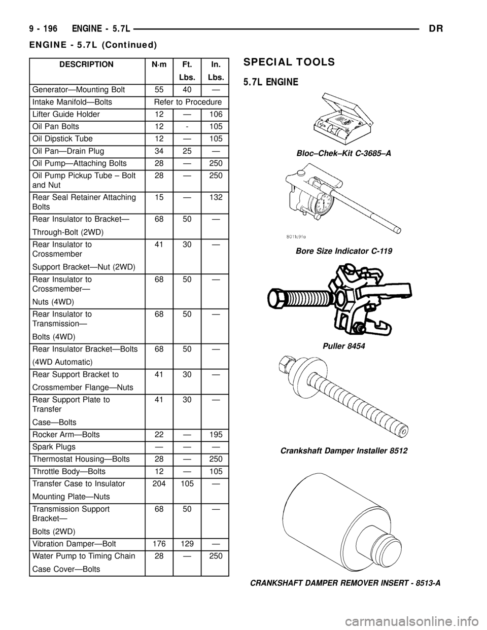
DESCRIPTION N´m Ft. In.
Lbs. Lbs.
GeneratorÐMounting Bolt 55 40 Ð
Intake ManifoldÐBolts Refer to Procedure
Lifter Guide Holder 12 Ð 106
Oil Pan Bolts 12 - 105
Oil Dipstick Tube 12 Ð 105
Oil PanÐDrain Plug 34 25 Ð
Oil PumpÐAttaching Bolts 28 Ð 250
Oil Pump Pickup Tube ± Bolt
and Nut28 Ð 250
Rear Seal Retainer Attaching
Bolts15 Ð 132
Rear Insulator to BracketÐ 68 50 Ð
Through-Bolt (2WD)
Rear Insulator to
Crossmember41 30 Ð
Support BracketÐNut (2WD)
Rear Insulator to
CrossmemberÐ68 50 Ð
Nuts (4WD)
Rear Insulator to
TransmissionÐ68 50 Ð
Bolts (4WD)
Rear Insulator BracketÐBolts 68 50 Ð
(4WD Automatic)
Rear Support Bracket to 41 30 Ð
Crossmember FlangeÐNuts
Rear Support Plate to
Transfer41 30 Ð
CaseÐBolts
Rocker ArmÐBolts 22 Ð 195
Spark Plugs Ð Ð Ð
Thermostat HousingÐBolts 28 Ð 250
Throttle BodyÐBolts 12 Ð 105
Transfer Case to Insulator 204 105 Ð
Mounting PlateÐNuts
Transmission Support
BracketÐ68 50 Ð
Bolts (2WD)
Vibration DamperÐBolt 176 129 Ð
Water Pump to Timing Chain 28 Ð 250
Case CoverÐBoltsSPECIAL TOOLS
5.7L ENGINE
CRANKSHAFT DAMPER REMOVER INSERT - 8513-A
Bloc±Chek±Kit C-3685±A
Bore Size Indicator C-119
Puller 8454
Crankshaft Damper Installer 8512
9 - 196 ENGINE - 5.7LDR
ENGINE - 5.7L (Continued)
Page 1420 of 2627
Dial Indicator C-3339
Handle C-4171
Oil Pressure Gauge C-3292
Piston Ring Compressor C-385
Pressure Tester Kit 7700
Rear Crankshaft Seal Installer 8349
Rear Crankshaft Seal Remover 8506
Valve Spring Compressor C-3422-B
Valve Spring Tester C-647
DRENGINE - 5.7L 9 - 197
ENGINE - 5.7L (Continued)
Page 1421 of 2627
Adapter, Valve Spring Compressor Off-vehicle 8464
ENGINE SUPPORT FIXTURE 8534
ENGINE LIFT FIXTURE 8984
REAR CAM PLUG INSTALLER 9048
VALVE SPRING COMPRESSOR - 9065
PUSHROD RETAINING PLATE - 9070
FRONT CRANK SEAL REMOVER - 9071
FRONT CRANK SEAL INSTALLER 9072
9 - 198 ENGINE - 5.7LDR
ENGINE - 5.7L (Continued)