1998 DODGE RAM 1500 Torque converter clutch solenoid
[x] Cancel search: Torque converter clutch solenoidPage 1109 of 2627
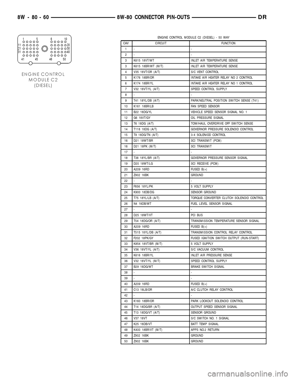
ENGINE CONTROL MODULE C2 (DIESEL) - 50 WAY
CAV CIRCUIT FUNCTION
1- -
2- -
3 K615 18VT/WT INLET AIR TEMPERATURE SENSE
3 K615 18BR/WT (M/T) INLET AIR TEMPERATURE SENSE
4 V35 18VT/OR (A/T) S/C VENT CONTROL
5 K176 18BR/OR INTAKE AIR HEATER RELAY NO 2 CONTROL
6 K174 18BR/YL INTAKE AIR HEATER RELAY NO 1 CONTROL
7 V32 18VT/YL (A/T) SPEED CONTROL SUPPLY
8- -
9 T41 18YL/DB (A/T) PARK/NEUTRAL POSITION SWITCH SENSE (T41)
10 K161 18BR/LB FAN SPEED SENSOR
11 B22 18DG/YL VEHICLE SPEED SENSOR SIGNAL NO. 1
12 G6 18VT/GY OIL PRESSURE SIGNAL
13 T6 18DG (A/T) TOW/HAUL OVERDRIVE OFF SWITCH SENSE
14 T118 18DG (A/T) GOVERNOR PRESSURE SOLENOID CONTROL
15 T9 18DG/TN (A/T) 3-4 SOLENIOD CONTROL
16 D21 18WT/BR SCI TRANSMIT (PCM)
16 D21 18PK (M/T) SCI TRANSMIT
17 - -
18 T38 18YL/BR (A/T) GOVERNOR PRESSURE SENSOR SIGNAL
19 D20 18WT/LG SCI RECEIVE (PCM)
20 A209 16RD FUSED B(+)
21 Z902 16BK GROUND
22 - -
23 F856 18YL/PK 5 VOLT SUPPLY
24 K900 18DB/DG SENSOR GROUND
25 T75 18YL/LB (A/T) TORQUE CONVERTER CLUTCH SOLENOID CONTROL
26 N4 18DB/WT FUEL LEVEL SENSOR SIGNAL
27 - -
28 D25 18WT/VT PCI BUS
29 T54 18DG/OR (A/T) TRANSMISSION TEMPERATURE SENSOR SIGNAL
30 A209 16RD FUSED B(+)
31 T515 18YL/DB (A/T) TRANSMISSION CONTROL RELAY CONTROL
32 F202 18PK/GY FUSED IGNITION SWITCH OUTPUT (RUN-START)
33 K854 18VT/BR (M/T) 5 VOLT SUPPLY
34 V36 18VT/YL (A/T) S/C VACUUM CONTROL
35 K616 18BR/YL INLET AIR PRESSURE SENSE
36 V32 18VT/YL (M/T) SPEED CONTROL SUPPLY
37 B29 18DG/WT BRAKE SWITCH SIGNAL
38 - -
39 - -
40 A209 16RD FUSED B(+)
41 C13 18LB/OR A/C CLUTCH RELAY CONTROL
42 - -
43 K160 18BR/OR PARK LOCKOUT SOLENOID CONTROL
44 T14 18DG/BR (A/T) OUTPUT SPEED SENSOR SIGNAL
45 T13 18DG/VT (A/T) SENSOR GROUND
46 V37 18VT S/C SWITCH NO. 1 SIGNAL
47 K25 18DB/VT BATT TEMP SIGNAL
48 K400 18BR/VT (M/T) APPS NO.2 RETURN
49 Z902 16BK GROUND
50 Z902 16BK GROUND
8W - 80 - 60 8W-80 CONNECTOR PIN-OUTSDR
Page 1151 of 2627
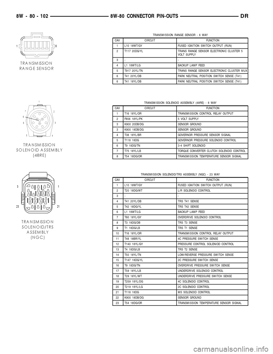
TRANSMISSION RANGE SENSOR-6WAY
CAV CIRCUIT FUNCTION
1 L10 18WT/GY FUSED IGNITION SWITCH OUTPUT (RUN)
2 T117 20DG/YL TRANS RANGE SENSOR ELECTRONIC CLUSTER 5
VOLT SUPPLY
3- -
4 L1 18WT/LG BACKUP LAMP FEED
5 T917 20YL/TN TRANS RANGE SENSOR ELECTRONIC CLUSTER MUX
6 T41 20YL/DB PARK NEUTRAL POSITION SWITCH SENSE (T41)
6 T41 18YL/DB PARK NEUTRAL POSITION SWITCH SENSE (T41)
TRANSMISSION SOLENOID ASSEMBLY (48RE)-8WAY
CAV CIRCUIT FUNCTION
1 T16 18YL/OR TRANSMISSION CONTROL RELAY OUTPUT
2 F856 18YL/PK 5 VOLT SUPPLY
3 K900 20DB/DG SENSOR GROUND
3 K900 18DB/DG SENSOR GROUND
4 T38 18YL/BR GOVERNOR PRESSURE SENSOR SIGNAL
5 T118 18DG GOVERNOR PRESSURE SOLENOID CONTROL
6 T9 18DG/TN 3-4 SHIFT SOLENOID
7 T75 18YL/LB TORQUE CONVERTER CLUTCH SOLENOID CONTROL
8 T54 18DG/OR TRANSMISSION TEMPERATURE SENSOR SIGNAL
TRANSMISSION SOLENOID/TRS ASSEMBLY (NGC) - 23 WAY
CAV CIRCUIT FUNCTION
1 L10 18WT/GY FUSED IGNITION SWITCH OUTPUT (RUN)
2 T20 18DG/WT L/R SOLENOID CONTROL
3- -
4 T41 20YL/DB TRS T41 SENSE
5 T42 18DG/YL TRS T42 SENSE
6 L1 18WT/LG BACKUP LAMP FEED
7 T60 18YL/GY OVERDRIVE SOLENOID CONTROL
8 T3 18DG/DB TRS T3 SENSE
9 T1 18DG/LB TRS T1 SENSE
10 T16 18YL/OR TRANSMISSION CONTROL RELAY OUTPUT
11 T48 18BR/YL 4C PRESSURE SWITCH SENSE
12 T140 18YL/GY PRESSURE CONTROL SOLENIOD CONTROL
13 T4 18DG/LB TRS T2 SENSE
14 T50 18YL/TN LOW/REVERSE PRESSURE SWITCH SENSE
15 T147 18DG/YL 2C PRESSURE SWITCH SENSE
16 T9 18DG/TN OVERDRIVE PRESSURE SWITCH SENSE
17 T59 18YL/LB UNDERDRIVE SOLENOID CONTROL
18 T29 18YL/WT UNDERDRIVE PRESSURE SWITCH SENSE
19 T259 18YL/DG 4C SOLENOID CONTROL
20 T219 18YL/LG 2C SOLENOID CONTROL
21 T118 18DG MS SOLENOID CONTROL
22 K900 18DB/DG SENSOR GROUND
23 T54 18DG/OR TRANSMISSION TEMPERATURE SENSOR SIGNAL
8W - 80 - 102 8W-80 CONNECTOR PIN-OUTSDR
Page 1834 of 2627

OUTPUT SHAFT FRONT BEARING
REMOVAL............................216
INSTALLATION........................216
OUTPUT SHAFT REAR BEARING
REMOVAL............................216
INSTALLATION........................217
OVERDRIVE CLUTCH
DESCRIPTION........................217
OPERATION..........................217
OVERDRIVE UNIT
REMOVAL............................218
DISASSEMBLY........................218
CLEANING...........................225
INSPECTION.........................225
ASSEMBLY...........................226
INSTALLATION........................235
OVERRUNNING CLUTCH CAM/OVERDRIVE
PISTON RETAINER
DESCRIPTION........................236
OPERATION..........................236
DISASSEMBLY........................236
CLEANING...........................236
INSPECTION.........................237
ASSEMBLY...........................237
PISTONS
DESCRIPTION........................239
OPERATION..........................239
PLANETARY GEARTRAIN/OUTPUT SHAFT
DESCRIPTION........................241
OPERATION..........................241
DISASSEMBLY........................242
INSPECTION.........................243
ASSEMBLY...........................244
REAR CLUTCH
DESCRIPTION........................247
OPERATION..........................248
DISASSEMBLY........................248
CLEANING...........................248
INSPECTION.........................248
ASSEMBLY...........................249
REAR SERVO
DESCRIPTION........................251
OPERATION..........................251
DISASSEMBLY........................251
CLEANING...........................251
ASSEMBLY...........................251
SHIFT MECHANISM
DESCRIPTION........................252OPERATION..........................252
SOLENOID
DESCRIPTION........................252
OPERATION..........................252
SPEED SENSOR
DESCRIPTION........................253
OPERATION..........................253
THROTTLE VALVE CABLE
DESCRIPTION........................253
ADJUSTMENTS - THROTTLE VALVE CABLE . 254
TORQUE CONVERTER
DESCRIPTION........................255
OPERATION..........................259
REMOVAL............................260
INSTALLATION........................260
TORQUE CONVERTER DRAINBACK VALVE
DESCRIPTION........................261
OPERATION..........................261
STANDARD PROCEDURE - TORQUE
CONVERTER DRAINBACK VALVE........261
TOW/HAUL OVERDRIVE SWITCH
DESCRIPTION........................261
OPERATION..........................262
DIAGNOSIS AND TESTING - OVERDRIVE
ELECTRICAL CONTROLS..............262
REMOVAL............................262
INSTALLATION........................262
TRANSMISSION RANGE SENSOR
DESCRIPTION........................263
OPERATION..........................263
DIAGNOSIS AND TESTING - TRANSMISSION
RANGE SENSOR (TRS)................264
REMOVAL............................265
INSTALLATION........................266
TRANSMISSION TEMPERATURE SENSOR
DESCRIPTION........................267
OPERATION..........................267
VALVE BODY
DESCRIPTION........................267
OPERATION..........................272
REMOVAL............................286
DISASSEMBLY........................287
CLEANING...........................298
INSPECTION.........................298
ASSEMBLY...........................299
INSTALLATION........................309
ADJUSTMENTS - VALVE BODY...........310
DRAUTOMATIC TRANSMISSION - 48RE 21 - 131
Page 1837 of 2627

IDENTIFICATION
Transmission identification numbers are stamped
on the left side of the case just above the oil pan gas-
ket surface (Fig. 2). Refer to this information when
ordering replacement parts.
GEAR RATIOS
The 48RE gear ratios are:
1st.................................2.45:1
2nd................................1.45:1
3rd................................1.00:1
4th.................................0.69:1
Rev.................................2.20:1
OPERATION
The application of each driving or holding compo-
nent is controlled by the valve body based upon the
manual lever position, throttle pressure, and gover-
nor pressure. The governor pressure is a variable
pressure input to the valve body and is one of the
signals that a shift is necessary. First through fourth
gear are obtained by selectively applying and releas-
ing the different clutches and bands. Engine power is
thereby routed to the various planetary gear assem-
blies which combine with the overrunning clutch
assemblies to generate the different gear ratios. The
torque converter clutch is hydraulically applied and
is released when fluid is vented from the hydraulic
circuit by the torque converter control (TCC) solenoid
on the valve body. The torque converter clutch is con-
trolled by the Powertrain Control Module (PCM). The
torque converter clutch engages in fourth gear, and
in third gear under various conditions, such as when
the O/D switch is OFF, when the vehicle is cruising
on a level surface after the vehicle has warmed up.
The torque converter clutch can also be engaged in
the MANUAL SECOND gear position if high trans-
mission temperatures are sensed by the PCM. The
torque converter clutch will disengage momentarily
when an increase in engine load is sensed by the
PCM, such as when the vehicle begins to go uphill or
the throttle pressure is increased. The torque con-
verter clutch feature increases fuel economy and
reduces the transmission fluid temperature.
Since the overdrive clutch is applied in fourth gear
only and the direct clutch is applied in all ranges
except fourth gear, the transmission operation for
park, neutral, and first through third gear will be
described first. Once these powerflows are described,
the third to fourth shift sequence will be described.
1 - TORQUE CONVERTER 10 - OVERDRIVE CLUTCH
2 - INPUT SHAFT 11 - DIRECT CLUTCH
3 - OIL PUMP 12 - PLANETARY GEAR
4 - FRONT BAND 13 - INTERMEDIATE SHAFT
5 - FRONT CLUTCH 14 - OVERDRIVE OVERRUNNING CLUTCH
6 - REAR CLUTCH 15 - DIRECT CLUTCH SPRING
7 - PLANETARIES 16 - OVERDRIVE PISTON RETAINER
8 - REAR BAND 17 - OIL PAN
9 - OVERRUNNING CLUTCH 18 - VALVE BODY
Fig. 2 Transmission Part Number And Serial
Number Location
1 - PART NUMBER
2 - BUILD DATE
3 - SERIAL NUMBER
21 - 134 AUTOMATIC TRANSMISSION - 48REDR
AUTOMATIC TRANSMISSION - 48RE (Continued)
Page 1850 of 2627
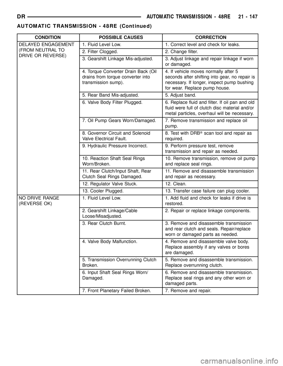
CONDITION POSSIBLE CAUSES CORRECTION
DELAYED ENGAGEMENT
(FROM NEUTRAL TO
DRIVE OR REVERSE)1. Fluid Level Low. 1. Correct level and check for leaks.
2. Filter Clogged. 2. Change filter.
3. Gearshift Linkage Mis-adjusted. 3. Adjust linkage and repair linkage if worn
or damaged.
4. Torque Converter Drain Back (Oil
drains from torque converter into
transmission sump).4. If vehicle moves normally after 5
seconds after shifting into gear, no repair is
necessary. If longer, inspect pump bushing
for wear. Replace pump house.
5. Rear Band Mis-adjusted. 5. Adjust band.
6. Valve Body Filter Plugged. 6. Replace fluid and filter. If oil pan and old
fluid were full of clutch disc material and/or
metal particles, overhaul will be necessary.
7. Oil Pump Gears Worn/Damaged. 7. Remove transmission and replace oil
pump.
8. Governor Circuit and Solenoid
Valve Electrical Fault.8. Test with DRBTscan tool and repair as
required.
9. Hydraulic Pressure Incorrect. 9. Perform pressure test, remove
transmission and repair as needed.
10. Reaction Shaft Seal Rings
Worn/Broken.10. Remove transmission, remove oil pump
and replace seal rings.
11. Rear Clutch/Input Shaft, Rear
Clutch Seal Rings Damaged.11. Remove and disassemble transmission
and repair as necessary.
12. Regulator Valve Stuck. 12. Clean.
13. Cooler Plugged. 13. Transfer case failure can plug cooler.
NO DRIVE RANGE
(REVERSE OK)1. Fluid Level Low. 1. Add fluid and check for leaks if drive is
restored.
2. Gearshift Linkage/Cable
Loose/Misadjusted.2. Repair or replace linkage components.
3. Rear Clutch Burnt. 3. Remove and disassemble transmission
and rear clutch and seals. Repair/replace
worn or damaged parts as needed.
4. Valve Body Malfunction. 4. Remove and disassemble valve body.
Replace assembly if any valves or bores
are damaged.
5. Transmission Overrunning Clutch
Broken.5. Remove and disassemble transmission.
Replace overrunning clutch.
6. Input Shaft Seal Rings Worn/
Damaged.6. Remove and disassemble transmission.
Replace seal rings and any other worn or
damaged parts.
7. Front Planetary Failed Broken. 7. Remove and repair.
DRAUTOMATIC TRANSMISSION - 48RE 21 - 147
AUTOMATIC TRANSMISSION - 48RE (Continued)
Page 1855 of 2627
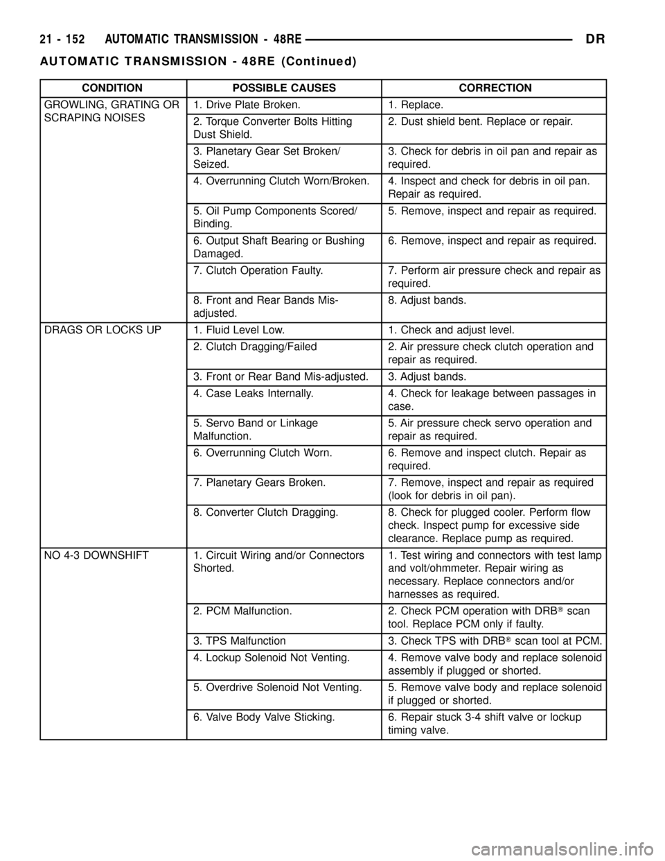
CONDITION POSSIBLE CAUSES CORRECTION
GROWLING, GRATING OR
SCRAPING NOISES1. Drive Plate Broken. 1. Replace.
2. Torque Converter Bolts Hitting
Dust Shield.2. Dust shield bent. Replace or repair.
3. Planetary Gear Set Broken/
Seized.3. Check for debris in oil pan and repair as
required.
4. Overrunning Clutch Worn/Broken. 4. Inspect and check for debris in oil pan.
Repair as required.
5. Oil Pump Components Scored/
Binding.5. Remove, inspect and repair as required.
6. Output Shaft Bearing or Bushing
Damaged.6. Remove, inspect and repair as required.
7. Clutch Operation Faulty. 7. Perform air pressure check and repair as
required.
8. Front and Rear Bands Mis-
adjusted.8. Adjust bands.
DRAGS OR LOCKS UP 1. Fluid Level Low. 1. Check and adjust level.
2. Clutch Dragging/Failed 2. Air pressure check clutch operation and
repair as required.
3. Front or Rear Band Mis-adjusted. 3. Adjust bands.
4. Case Leaks Internally. 4. Check for leakage between passages in
case.
5. Servo Band or Linkage
Malfunction.5. Air pressure check servo operation and
repair as required.
6. Overrunning Clutch Worn. 6. Remove and inspect clutch. Repair as
required.
7. Planetary Gears Broken. 7. Remove, inspect and repair as required
(look for debris in oil pan).
8. Converter Clutch Dragging. 8. Check for plugged cooler. Perform flow
check. Inspect pump for excessive side
clearance. Replace pump as required.
NO 4-3 DOWNSHIFT 1. Circuit Wiring and/or Connectors
Shorted.1. Test wiring and connectors with test lamp
and volt/ohmmeter. Repair wiring as
necessary. Replace connectors and/or
harnesses as required.
2. PCM Malfunction. 2. Check PCM operation with DRBTscan
tool. Replace PCM only if faulty.
3. TPS Malfunction 3. Check TPS with DRBTscan tool at PCM.
4. Lockup Solenoid Not Venting. 4. Remove valve body and replace solenoid
assembly if plugged or shorted.
5. Overdrive Solenoid Not Venting. 5. Remove valve body and replace solenoid
if plugged or shorted.
6. Valve Body Valve Sticking. 6. Repair stuck 3-4 shift valve or lockup
timing valve.
21 - 152 AUTOMATIC TRANSMISSION - 48REDR
AUTOMATIC TRANSMISSION - 48RE (Continued)
Page 1858 of 2627
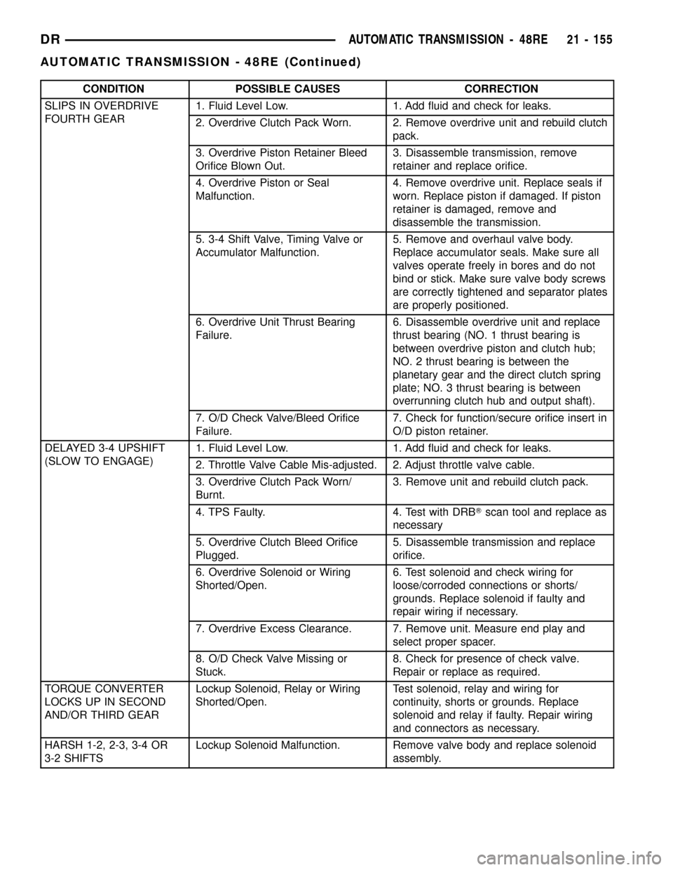
CONDITION POSSIBLE CAUSES CORRECTION
SLIPS IN OVERDRIVE
FOURTH GEAR1. Fluid Level Low. 1. Add fluid and check for leaks.
2. Overdrive Clutch Pack Worn. 2. Remove overdrive unit and rebuild clutch
pack.
3. Overdrive Piston Retainer Bleed
Orifice Blown Out.3. Disassemble transmission, remove
retainer and replace orifice.
4. Overdrive Piston or Seal
Malfunction.4. Remove overdrive unit. Replace seals if
worn. Replace piston if damaged. If piston
retainer is damaged, remove and
disassemble the transmission.
5. 3-4 Shift Valve, Timing Valve or
Accumulator Malfunction.5. Remove and overhaul valve body.
Replace accumulator seals. Make sure all
valves operate freely in bores and do not
bind or stick. Make sure valve body screws
are correctly tightened and separator plates
are properly positioned.
6. Overdrive Unit Thrust Bearing
Failure.6. Disassemble overdrive unit and replace
thrust bearing (NO. 1 thrust bearing is
between overdrive piston and clutch hub;
NO. 2 thrust bearing is between the
planetary gear and the direct clutch spring
plate; NO. 3 thrust bearing is between
overrunning clutch hub and output shaft).
7. O/D Check Valve/Bleed Orifice
Failure.7. Check for function/secure orifice insert in
O/D piston retainer.
DELAYED 3-4 UPSHIFT
(SLOW TO ENGAGE)1. Fluid Level Low. 1. Add fluid and check for leaks.
2. Throttle Valve Cable Mis-adjusted. 2. Adjust throttle valve cable.
3. Overdrive Clutch Pack Worn/
Burnt.3. Remove unit and rebuild clutch pack.
4. TPS Faulty. 4. Test with DRBTscan tool and replace as
necessary
5. Overdrive Clutch Bleed Orifice
Plugged.5. Disassemble transmission and replace
orifice.
6. Overdrive Solenoid or Wiring
Shorted/Open.6. Test solenoid and check wiring for
loose/corroded connections or shorts/
grounds. Replace solenoid if faulty and
repair wiring if necessary.
7. Overdrive Excess Clearance. 7. Remove unit. Measure end play and
select proper spacer.
8. O/D Check Valve Missing or
Stuck.8. Check for presence of check valve.
Repair or replace as required.
TORQUE CONVERTER
LOCKS UP IN SECOND
AND/OR THIRD GEARLockup Solenoid, Relay or Wiring
Shorted/Open.Test solenoid, relay and wiring for
continuity, shorts or grounds. Replace
solenoid and relay if faulty. Repair wiring
and connectors as necessary.
HARSH 1-2, 2-3, 3-4 OR
3-2 SHIFTSLockup Solenoid Malfunction. Remove valve body and replace solenoid
assembly.
DRAUTOMATIC TRANSMISSION - 48RE 21 - 155
AUTOMATIC TRANSMISSION - 48RE (Continued)
Page 1878 of 2627

(13) Install bolts attaching converter housing to
engine.
(14) Install rear support.
(15) Install the rear transmission crossmember.
(16) Lower transmission onto crossmember and
install bolts attaching transmission mount to cross-
member.
(17) Remove engine support fixture.
(18) Install the transfer case, if equipped.
(19) Install crankshaft position sensor. (Refer to 14
- FUEL SYSTEM/FUEL INJECTION/CRANKSHAFT
POSITION SENSOR - INSTALLATION)
(20) Connect gearshift cable (Fig. 64) and throttle
cable to transmission.
(21) Connect wires to the transmission range sen-
sor and transmission solenoid connector. Be sure the
transmission harnesses are properly routed.
CAUTION: It is essential that correct length bolts be
used to attach the converter to the driveplate. Bolts
that are too long will damage the clutch surface
inside the converter.(22) Install torque converter-to-driveplate bolts.
(23) Install converter housing access cover.
(24) Install starter motor and cooler line bracket.
(Refer to 8 - ELECTRICAL/STARTING/STARTER
MOTOR - INSTALLATION)
(25) Connect cooler lines (Fig. 65) to transmission.
(26) Install transmission fill tube. Install new seal
on tube before installation.
(27) Install any exhaust components previously
removed.
(28) Align and connect propeller shaft. (Refer to 3 -
DIFFERENTIAL & DRIVELINE/PROPELLER
SHAFT/PROPELLER SHAFT - INSTALLATION)
(29) Adjust gearshift cable and throttle valve
cable, if necessary.
(30) Install the transfer case skid plate, if
equipped.
(31) Lower vehicle.
(32) Fill transmission with MopartATF +4, Auto-
matic Transmission fluid.
Fig. 64 Gearshift Cable At Transmission
1 - GEARSHIFT CABLE
2 - TRANSMISSION MANUAL LEVER
3 - CABLE SUPPORT BRACKET
Fig. 65 Transmission Cooler Lines
1 - TRANSMISSION
2 - RADIATOR
3 - COOLER LINES
DRAUTOMATIC TRANSMISSION - 48RE 21 - 175
AUTOMATIC TRANSMISSION - 48RE (Continued)