1998 DODGE RAM 1500 Engine torque spec
[x] Cancel search: Engine torque specPage 1484 of 2627
(g) Release the spring tension and remove the
compressor. Verify that the collets are seated by
tapping on the valve stem with a plastic hammer.
(12) Using the crankshaft barring tool, rotate the
engine until the next crankshaft damper paint mark
aligns with the mark you placed on the cover.In this
position, cylinders #2 and #5 can be serviced.
(13) Repeat the valve spring compressing proce-
dure previously performed and service the retainers,
springs, and seals as necessary.
(14) Using the crankshaft barring tool, rotate the
engine until the next crankshaft damper paint mark
aligns with the mark you placed on the cover.In this
position, cylinders #3 and #4 can be serviced.
(15) Repeat the spring compressing procedure pre-
viously performed and service the retainers, springs,
and seals as necessary.
INSTALLATION
(1) Install rocker housing.
(2) Install fuel injectors and high pressure fuel
lines.
(3) Lubricate the valve tips and install the cross-
heads in their original locations.
(4) Lubricate the crossheads and push rod sockets
and install the rocker arms and pedestals in their
original locations. Tighten bolts to 36 N´m (27 ft. lbs.)
torque.
(5)Verify valve lash adjustment (Refer to 9 -
ENGINE/CYLINDER HEAD/INTAKE/EXHAUST
VALVES & SEATS - STANDARD PROCEDURE).
(6) Install cylinder head cover and reusable gasket
(Refer to 9 - ENGINE/CYLINDER HEAD/CYLIN-
DER HEAD COVER(S) - INSTALLATION).
(7) Connect battery negative cables.
ROCKER ARM / ADJUSTER
ASSY
DESCRIPTION
The unique intake and exhaust rocker arms have
their own rocker shafts and are lubricated by pas-
sages intersecting the cylinder block main oil rifle.
Crossheads are used, which allow each rocker arm to
operate two valves.
The solid push rods are hardened at the rocker
arm and tappet contact areas for superior strength
and durability.
REMOVAL
(1) Disconnect the battery negative cables.
(2) Remove cylinder head cover (Refer to 9 -
ENGINE/CYLINDER HEAD/CYLINDER HEAD
COVER(S) - REMOVAL).
(3) Remove the rocker arm/pedestal fasteners (Fig.
36) and remove rocker arm and pedestal from cylin-
der head. Mark the arms and pedestals so they can
be installed in their original position.
CAUTION: When removing the rocker arms, the
sockets (Fig. 37) may come loose and fall into the
engine. Make sure they stay with the arm upon
removal/installation.
(4) Lift the push rod(s) up and out of the engine
(Fig. 38). Mark them so they can be installed in their
original position.
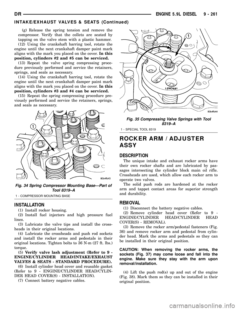
Fig. 34 Spring Compressor Mounting BaseÐPart of
Tool 8319±A
1 - COMPRESSOR MOUNTING BASE
Fig. 35 Compressing Valve Springs with Tool
8319±A
1 - SPECIAL TOOL 8319
DRENGINE 5.9L DIESEL 9 - 261
INTAKE/EXHAUST VALVES & SEATS (Continued)
Page 1486 of 2627
Push Rods
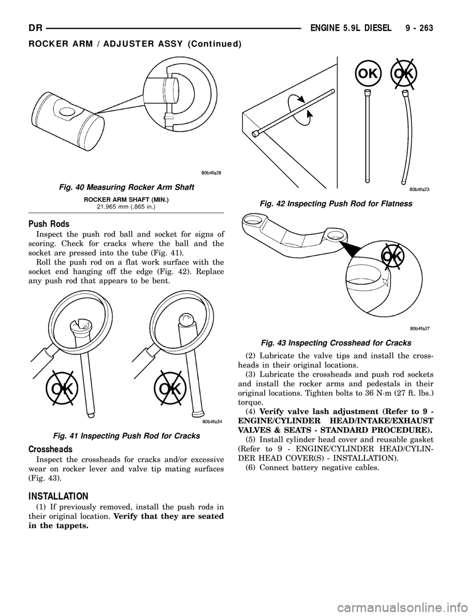
Inspect the push rod ball and socket for signs of
scoring. Check for cracks where the ball and the
socket are pressed into the tube (Fig. 41).
Roll the push rod on a flat work surface with the
socket end hanging off the edge (Fig. 42). Replace
any push rod that appears to be bent.
Crossheads
Inspect the crossheads for cracks and/or excessive
wear on rocker lever and valve tip mating surfaces
(Fig. 43).
INSTALLATION
(1) If previously removed, install the push rods in
their original location.Verify that they are seated
in the tappets.(2) Lubricate the valve tips and install the cross-
heads in their original locations.
(3) Lubricate the crossheads and push rod sockets
and install the rocker arms and pedestals in their
original locations. Tighten bolts to 36 N´m (27 ft. lbs.)
torque.
(4)Verify valve lash adjustment (Refer to 9 -
ENGINE/CYLINDER HEAD/INTAKE/EXHAUST
VALVES & SEATS - STANDARD PROCEDURE).
(5) Install cylinder head cover and reusable gasket
(Refer to 9 - ENGINE/CYLINDER HEAD/CYLIN-
DER HEAD COVER(S) - INSTALLATION).
(6) Connect battery negative cables.
Fig. 40 Measuring Rocker Arm Shaft
ROCKER ARM SHAFT (MIN.)
21.965 mm (.865 in.)
Fig. 41 Inspecting Push Rod for Cracks
Fig. 42 Inspecting Push Rod for Flatness
Fig. 43 Inspecting Crosshead for Cracks
DRENGINE 5.9L DIESEL 9 - 263
ROCKER ARM / ADJUSTER ASSY (Continued)
Page 1494 of 2627
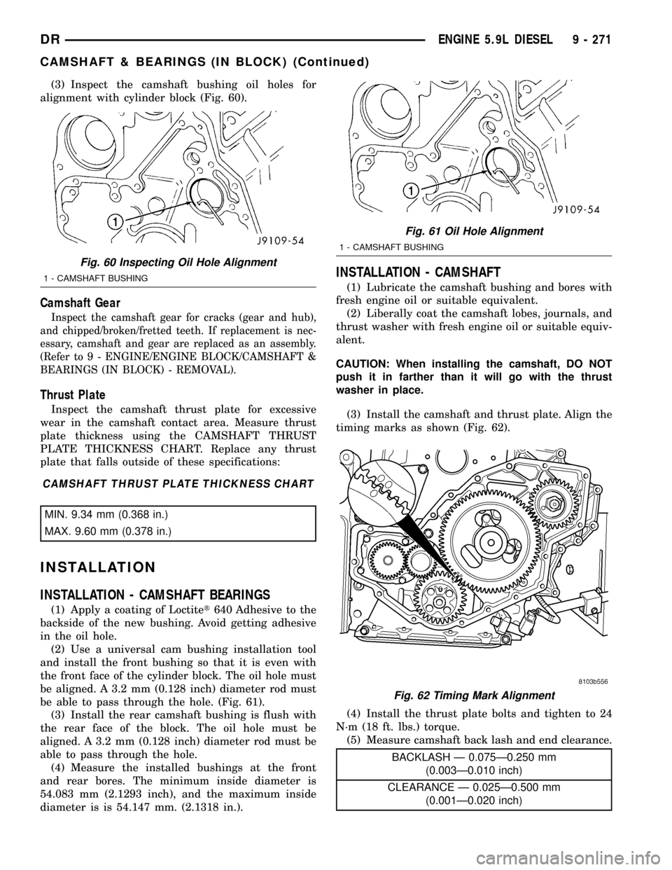
(3) Inspect the camshaft bushing oil holes for
alignment with cylinder block (Fig. 60).
Camshaft Gear
Inspect the camshaft gear for cracks (gear and hub),
and chipped/broken/fretted teeth. If replacement is nec-
essary, camshaft and gear are replaced as an assembly.
(Refer to 9 - ENGINE/ENGINE BLOCK/CAMSHAFT &
BEARINGS (IN BLOCK) - REMOVAL).
Thrust Plate
Inspect the camshaft thrust plate for excessive
wear in the camshaft contact area. Measure thrust
plate thickness using the CAMSHAFT THRUST
PLATE THICKNESS CHART. Replace any thrust
plate that falls outside of these specifications:
CAMSHAFT THRUST PLATE THICKNESS CHART
MIN. 9.34 mm (0.368 in.)
MAX. 9.60 mm (0.378 in.)
INSTALLATION
INSTALLATION - CAMSHAFT BEARINGS
(1) Apply a coating of Loctitet640 Adhesive to the
backside of the new bushing. Avoid getting adhesive
in the oil hole.
(2) Use a universal cam bushing installation tool
and install the front bushing so that it is even with
the front face of the cylinder block. The oil hole must
be aligned. A 3.2 mm (0.128 inch) diameter rod must
be able to pass through the hole. (Fig. 61).
(3) Install the rear camshaft bushing is flush with
the rear face of the block. The oil hole must be
aligned. A 3.2 mm (0.128 inch) diameter rod must be
able to pass through the hole.
(4) Measure the installed bushings at the front
and rear bores. The minimum inside diameter is
54.083 mm (2.1293 inch), and the maximum inside
diameter is is 54.147 mm. (2.1318 in.).
INSTALLATION - CAMSHAFT
(1) Lubricate the camshaft bushing and bores with
fresh engine oil or suitable equivalent.
(2) Liberally coat the camshaft lobes, journals, and
thrust washer with fresh engine oil or suitable equiv-
alent.
CAUTION: When installing the camshaft, DO NOT
push it in farther than it will go with the thrust
washer in place.
(3) Install the camshaft and thrust plate. Align the
timing marks as shown (Fig. 62).
(4) Install the thrust plate bolts and tighten to 24
N´m (18 ft. lbs.) torque.
(5) Measure camshaft back lash and end clearance.
BACKLASH Ð 0.075Ð0.250 mm
(0.003Ð0.010 inch)
CLEARANCE Ð 0.025Ð0.500 mm
(0.001Ð0.020 inch)
Fig. 60 Inspecting Oil Hole Alignment
1 - CAMSHAFT BUSHING
Fig. 61 Oil Hole Alignment
1 - CAMSHAFT BUSHING
Fig. 62 Timing Mark Alignment
DRENGINE 5.9L DIESEL 9 - 271
CAMSHAFT & BEARINGS (IN BLOCK) (Continued)
Page 1497 of 2627
CRANKSHAFT MAIN
BEARINGS
STANDARD PROCEDURE - MAIN BEARING
CLEARANCE
Inspect the main bearing bores for damage or
abnormal wear.
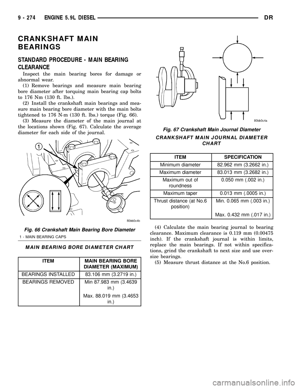
(1) Remove bearings and measure main bearing
bore diameter after torquing main bearing cap bolts
to 176 Nm (130 ft. lbs.).
(2) Install the crankshaft main bearings and mea-
sure main bearing bore diameter with the main bolts
tightened to 176 N´m (130 ft. lbs.) torque (Fig. 66).
(3) Measure the diameter of the main journal at
the locations shown (Fig. 67). Calculate the average
diameter for each side of the journal.
MAIN BEARING BORE DIAMETER CHART
ITEM MAIN BEARING BORE
DIAMETER (MAXIMUM)
BEARINGS INSTALLED 83.106 mm (3.2719 in.)
BEARINGS REMOVED Min 87.983 mm (3.4639
in.)
Max. 88.019 mm (3.4653
in.)
CRANKSHAFT MAIN JOURNAL DIAMETER
CHART
ITEM SPECIFICATION
Minimum diameter 82.962 mm (3.2662 in.)
Maximum diameter 83.013 mm (3.2682 in.)
Maximum out of
roundness0.050 mm (.002 in.)
Maximum taper 0.013 mm (.0005 in.)
Thrust distance (at No.6
position)Min. 0.065 mm (.003 in.)
Max. 0.432 mm (.017 in.)
(4) Calculate the main bearing journal to bearing
clearance. Maximum clearance is 0.119 mm (0.00475
inch). If the crankshaft journal is within limits,
replace the main bearings. If not within specifica-
tions, grind the crankshaft to next size and use over-
size bearings.
(5) Measure thrust distance at the No.6 position.
Fig. 66 Crankshaft Main Bearing Bore Diameter
1 - MAIN BEARING CAPS
Fig. 67 Crankshaft Main Journal Diameter
9 - 274 ENGINE 5.9L DIESELDR
Page 1499 of 2627
(6) Apply a bead of MopartSilicone Rubber Adhe-
sive Sealant or equivalent to the gear housing cover
sealing surface.
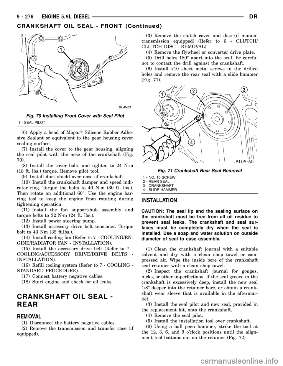
(7) Install the cover to the gear housing, aligning
the seal pilot with the nose of the crankshaft (Fig.
70).
(8) Install the cover bolts and tighten to 24 N´m
(18 ft. lbs.) torque. Remove pilot tool.
(9) Install dust shield over nose of crankshaft.
(10) Install the crankshaft damper and speed indi-
cator ring. Torque the bolts to 40 N´m (30 ft. lbs.).
Then rotate an additional 60É. Use the engine bar-
ring tool to keep the engine from rotating during
tightening operation.
(11) Install the fan support/hub assembly and
torque bolts to 32 N´m (24 ft. lbs.).
(12) Install power steering pump.
(13) Install accessory drive belt tensioner. Torque
bolt to 43 Nm (32 ft.lbs.).
(14) Install cooling fan (Refer to 7 - COOLING/EN-
GINE/RADIATOR FAN - INSTALLATION).
(15) Install the accessory drive belt (Refer to 7 -
COOLING/ACCESSORY DRIVE/DRIVE BELTS -
INSTALLATION).
(16) Refill cooling system (Refer to 7 - COOLING -
STANDARD PROCEDURE).
(17) Connect battery negative cables.
(18) Start engine and check for oil leaks.
CRANKSHAFT OIL SEAL -
REAR
REMOVAL
(1) Disconnect the battery negative cables.
(2) Remove the transmission and transfer case (if
equipped).(3) Remove the clutch cover and disc (if manual
transmission equipped) (Refer to 6 - CLUTCH/
CLUTCH DISC - REMOVAL).
(4) Remove the flywheel or converter drive plate.
(5) Drill holes 180É apart into the seal. Be careful
not to contact the drill against the crankshaft.
(6) Install #10 sheet metal screws in the drilled
holes and remove the rear seal with a slide hammer
(Fig. 71).
INSTALLATION
CAUTION: The seal lip and the sealing surface on
the crankshaft must be free from all oil residue to
prevent seal leaks. The crankshaft and seal sur-
faces must be completely dry when the seal is
installed. Use a soap and water solution on outside
diameter of seal to ease assembly.
(1) Clean the crankshaft journal with a suitable
solvent and dry with a clean shop towel or com-
pressed air. Wipe the inside bore of the crankshaft
seal retainer with a clean shop towel.
(2) Inspect the crankshaft journal for gouges,
nicks, or other imperfections. If the seal groove in the
crankshaft is excessively deep, install the new seal
1/8º deeper into the retainer bore, or obtain a crank-
shaft wear sleeve that is available in the aftermar-
ket.
(3) Install the seal pilot and new seal, provided in
the replacement kit, onto the crankshaft.
(4) Remove the seal pilot.
(5) Install the installation tool over crankshaft.
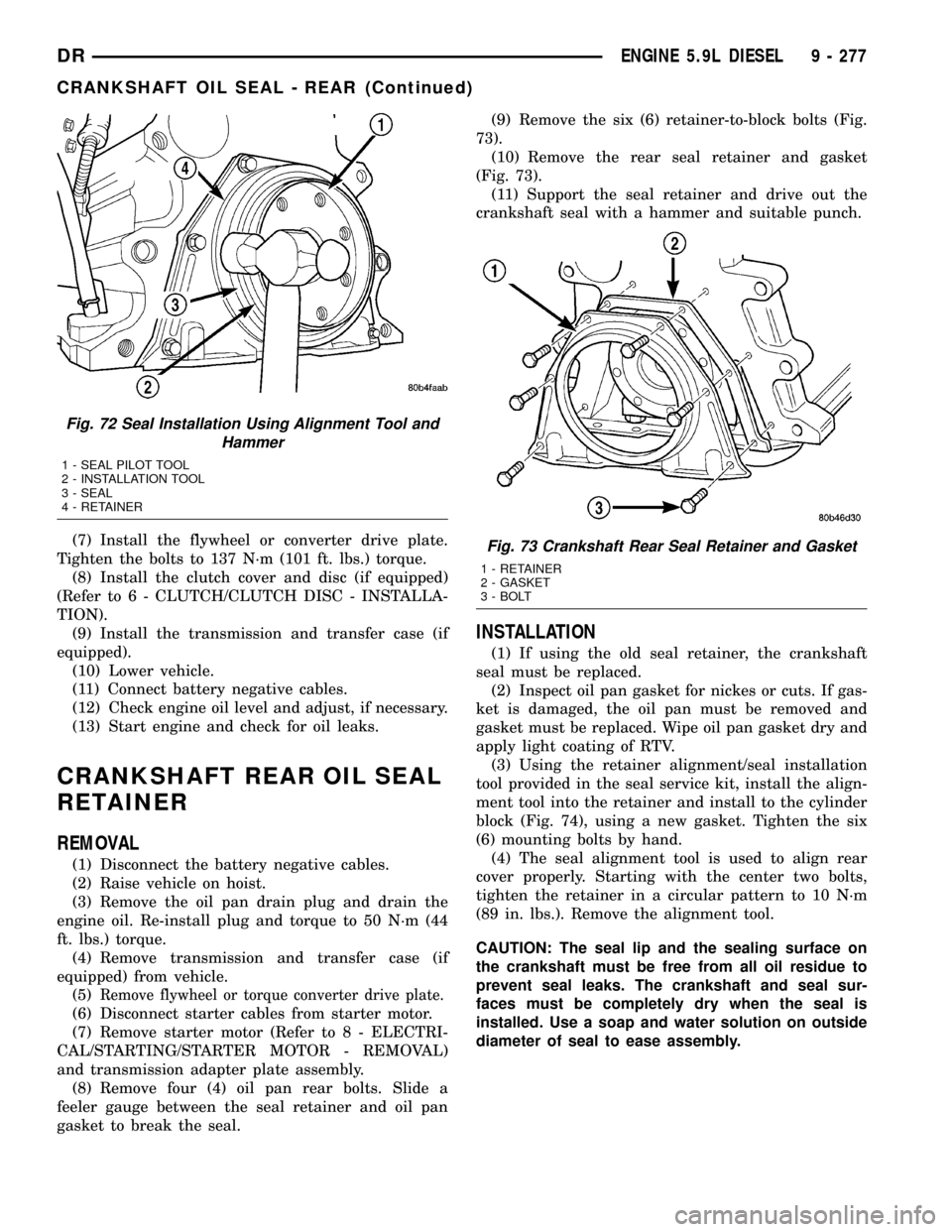
(6) Using a ball peen hammer, strike the tool at
the 12, 3, 6, and 9 o'clock positions until the align-
ment tool bottoms out on the retainer (Fig. 72).
Fig. 70 Installing Front Cover with Seal Pilot
1 - SEAL PILOT
Fig. 71 Crankshaft Rear Seal Removal
1 - NO. 10 SCREW
2 - REAR SEAL
3 - CRANKSHAFT
4 - SLIDE HAMMER
9 - 276 ENGINE 5.9L DIESELDR
CRANKSHAFT OIL SEAL - FRONT (Continued)
Page 1500 of 2627
(7) Install the flywheel or converter drive plate.
Tighten the bolts to 137 N´m (101 ft. lbs.) torque.
(8) Install the clutch cover and disc (if equipped)
(Refer to 6 - CLUTCH/CLUTCH DISC - INSTALLA-
TION).
(9) Install the transmission and transfer case (if
equipped).
(10) Lower vehicle.
(11) Connect battery negative cables.
(12) Check engine oil level and adjust, if necessary.
(13) Start engine and check for oil leaks.
CRANKSHAFT REAR OIL SEAL
RETAINER
REMOVAL
(1) Disconnect the battery negative cables.
(2) Raise vehicle on hoist.
(3) Remove the oil pan drain plug and drain the
engine oil. Re-install plug and torque to 50 N´m (44
ft. lbs.) torque.
(4) Remove transmission and transfer case (if
equipped) from vehicle.
(5)
Remove flywheel or torque converter drive plate.
(6) Disconnect starter cables from starter motor.
(7) Remove starter motor (Refer to 8 - ELECTRI-
CAL/STARTING/STARTER MOTOR - REMOVAL)
and transmission adapter plate assembly.
(8) Remove four (4) oil pan rear bolts. Slide a
feeler gauge between the seal retainer and oil pan
gasket to break the seal.(9) Remove the six (6) retainer-to-block bolts (Fig.
73).
(10) Remove the rear seal retainer and gasket
(Fig. 73).
(11) Support the seal retainer and drive out the
crankshaft seal with a hammer and suitable punch.
INSTALLATION
(1) If using the old seal retainer, the crankshaft
seal must be replaced.
(2) Inspect oil pan gasket for nickes or cuts. If gas-
ket is damaged, the oil pan must be removed and
gasket must be replaced. Wipe oil pan gasket dry and
apply light coating of RTV.
(3) Using the retainer alignment/seal installation
tool provided in the seal service kit, install the align-
ment tool into the retainer and install to the cylinder
block (Fig. 74), using a new gasket. Tighten the six
(6) mounting bolts by hand.
(4) The seal alignment tool is used to align rear
cover properly. Starting with the center two bolts,
tighten the retainer in a circular pattern to 10 N´m
(89 in. lbs.). Remove the alignment tool.
CAUTION: The seal lip and the sealing surface on
the crankshaft must be free from all oil residue to
prevent seal leaks. The crankshaft and seal sur-
faces must be completely dry when the seal is
installed. Use a soap and water solution on outside
diameter of seal to ease assembly.
Fig. 72 Seal Installation Using Alignment Tool and
Hammer
1 - SEAL PILOT TOOL
2 - INSTALLATION TOOL
3 - SEAL
4 - RETAINER
Fig. 73 Crankshaft Rear Seal Retainer and Gasket
1 - RETAINER
2 - GASKET
3 - BOLT
DRENGINE 5.9L DIESEL 9 - 277
CRANKSHAFT OIL SEAL - REAR (Continued)
Page 1509 of 2627
INSTALLATION
(1) Install speed indicator ring.
NOTE: The speed indicator ring is located over a
dowel pin.
(2) Install the crankshaft damper and bolts.
Tighten bolts to 40 N´m (30 ft. lbs.) torque, plus an
additional 60É.
NOTE: The damper must be installed so the hole is
located over the dowel pin.
(3) Install the accessory drive belt (Refer to 7 -
COOLING/ACCESSORY DRIVE/DRIVE BELTS -
INSTALLATION).
FRONT MOUNT
REMOVAL
(1) Disconnect the battery negative cables.
(2) Remove the viscous fan/drive assembly (Refer
to 7 - COOLING/ENGINE/RADIATOR FAN -
REMOVAL).
(3) Raise vehicle on hoist.
(4) Install engine support fixture tool# 8534 and
steel bracket tool # 8534A
(5) Loosen the thru-bolt and nut.
(6) Lift the engine SLIGHTLY and remove the
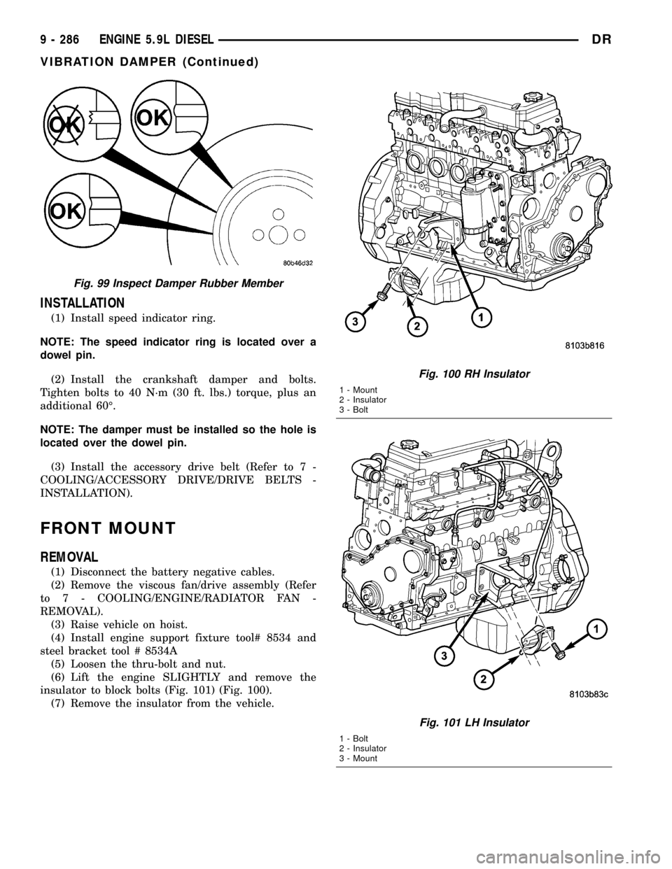
insulator to block bolts (Fig. 101) (Fig. 100).
(7) Remove the insulator from the vehicle.
Fig. 99 Inspect Damper Rubber Member
Fig. 100 RH Insulator
1 - Mount
2 - Insulator
3 - Bolt
Fig. 101 LH Insulator
1 - Bolt
2 - Insulator
3 - Mount
9 - 286 ENGINE 5.9L DIESELDR
VIBRATION DAMPER (Continued)
Page 1510 of 2627
INSTALLATION
(1) With engine raised SLIGHTLY, position the
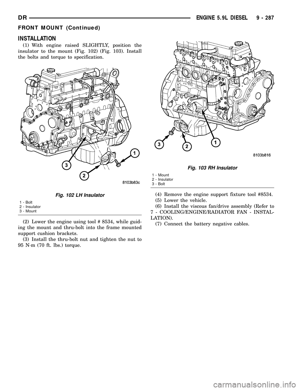
insulator to the mount (Fig. 102) (Fig. 103). Install
the bolts and torque to specification.
(2) Lower the engine using tool # 8534, while guid-
ing the mount and thru-bolt into the frame mounted
support cushion brackets.
(3) Install the thru-bolt nut and tighten the nut to
95 N´m (70 ft. lbs.) torque.(4) Remove the engine support fixture tool #8534.
(5) Lower the vehicle.
(6) Install the viscous fan/drive assembly (Refer to
7 - COOLING/ENGINE/RADIATOR FAN - INSTAL-
LATION).
(7) Connect the battery negative cables.
Fig. 102 LH Insulator
1 - Bolt
2 - Insulator
3 - Mount
Fig. 103 RH Insulator
1 - Mount
2 - Insulator
3 - Bolt
DRENGINE 5.9L DIESEL 9 - 287
FRONT MOUNT (Continued)