Page 726 of 2627

WIRING
TABLE OF CONTENTS
page page
WIRING DIAGRAM INFORMATION....... 8W-01-1
COMPONENT INDEX.................. 8W-02-1
POWER DISTRIBUTION............... 8W-10-1
GROUND DISTRIBUTION.............. 8W-15-1
BUS COMMUNICATIONS.............. 8W-18-1
CHARGING SYSTEM.................. 8W-20-1
STARTING SYSTEM.................. 8W-21-1
FUEL/IGNITION SYSTEM.............. 8W-30-1
TRANSMISSION CONTROL SYSTEM..... 8W-31-1
VEHICLE SPEED CONTROL............ 8W-33-1
REAR WHEEL ANTILOCK BRAKES....... 8W-34-1
ALL WHEEL ANTILOCK BRAKES........ 8W-35-1
VEHICLE THEFT SECURITY SYSTEM..... 8W-39-1
INSTRUMENT CLUSTER............... 8W-40-1
HORN/CIGAR LIGHTER/POWER OUTLET . . 8W-41-1
AIR CONDITIONING.................. 8W-42-1
AIRBAG SYSTEM.................... 8W-43-1
INTERIOR LIGHTING.................. 8W-44-1AUDIO SYSTEM..................... 8W-47-1
REAR WINDOW DEFOGGER............ 8W-48-1
OVERHEAD CONSOLE................. 8W-49-1
FRONT LIGHTING.................... 8W-50-1
REAR LIGHTING..................... 8W-51-1
TURN SIGNALS...................... 8W-52-1
WIPERS............................ 8W-53-1
TRAILER TOW....................... 8W-54-1
NAVIGATION/TELECOMMUNICATION..... 8W-55-1
POWER WINDOWS................... 8W-60-1
POWER DOOR LOCKS................ 8W-61-1
POWER MIRRORS................... 8W-62-1
POWER SEATS...................... 8W-63-1
SPLICE INFORMATION................ 8W-70-1
CONNECTOR PIN-OUTS............... 8W-80-1
CONNECTOR/GROUND/SPLICE
LOCATION........................ 8W-91-1
POWER DISTRIBUTION............... 8W-97-1 DRWIRING 8W - 1
Page 1712 of 2627

(11) Remove reverse idler shaft support bolt and
loosen rear reverse idler shaft bolt (Fig. 22).
(12) Remove reverse idler shaft support segment
by sliding it straight out of housing.
(13) Support geartrain and rear housing on Fix-
ture 6747 as follows:
(a) Adjust height of reverse idler pedestal rod
until the reverse idle shaft bottoms in Cup 8115.
(b) Position Adapters 6747-1A and 6747-2A on
Fixture 6747.
(c) Slide fixture tool onto input shaft, counter-
shaft and idler gear (Fig. 23).
(d) Stand geartrain and rear housing upright on
fixture (Fig. 24). Have helper hold fixture tool in
place while housing and geartrain is being rotated
into upright position.(14) Remove rear bolt holding reverse idler shaft
in housing.
Fig. 22 REVERSE IDLER SHAFT & SUPPORT
1 - SUPPORT BOLT
2 - SHAFT BOLT
Fig. 23 FIXTURE ASSEMBLY
1 - FIXTURE 6747
2 - ADAPTER 6747-1A
3 - CUP ADAPTER 8115
4 - REVERSE IDLER PEDESTAL
5 - ADAPTER 6747-2A
Fig. 24 GEARTRAIN & HOUSING ON FIXTURE
1 - INPUT SHAFT
2 - COUNTERSHAFT
3 - FIXTURE 6747
DRMANUAL TRANSMISSION - NV3500 21 - 9
MANUAL TRANSMISSION - NV3500 (Continued)
Page 1730 of 2627

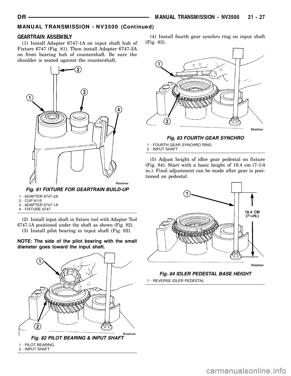
GEARTRAIN ASSEMBLY
(1) Install Adapter 6747-1A on input shaft hub of
Fixture 6747 (Fig. 81). Then install Adapter 6747-2A
on front bearing hub of countershaft. Be sure the
shoulder is seated against the countershaft.
(2)
Install input shaft in fixture tool with Adapter Tool
6747-1A positioned under the shaft as shown (Fig. 82).
(3) Install pilot bearing in input shaft (Fig. 82).
NOTE: The side of the pilot bearing with the small
diameter goes toward the input shaft.(4) Install fourth gear synchro ring on input shaft
(Fig. 83).
(5) Adjust height of idler gear pedestal on fixture
(Fig. 84). Start with a basic height of 18.4 cm (7-1/4
in.). Final adjustment can be made after gear is posi-
tioned on pedestal.
Fig. 81 FIXTURE FOR GEARTRAIN BUILD-UP
1 - ADAPTER 6747-2A
2 - CUP 8115
3 - ADAPTER 6747-1A
4 - FIXTURE 6747
Fig. 82 PILOT BEARING & INPUT SHAFT
1 - PILOT BEARING
2 - INPUT SHAFT
Fig. 83 FOURTH GEAR SYNCHRO
1 - FOURTH GEAR SYNCHRO RING
2 - INPUT SHAFT
Fig. 84 IDLER PEDESTAL BASE HEIGHT
1 - REVERSE IDLER PEDESTAL
DRMANUAL TRANSMISSION - NV3500 21 - 27
MANUAL TRANSMISSION - NV3500 (Continued)
Page 1744 of 2627
REMOVER/INSTALLER 6858
FIXTURE 6747
ADAPTER 6747-1A
ADAPTER 6747-2A
CUP 8115
BEARING SPLITTER 1130
TUBE 6310-1
INSTALLER 8118
REMOVER/INSTALLER 8119
ALIGNMENT STUD 8120
DRMANUAL TRANSMISSION - NV3500 21 - 41
MANUAL TRANSMISSION - NV3500 (Continued)