1998 DODGE RAM 1500 tow
[x] Cancel search: towPage 1364 of 2627
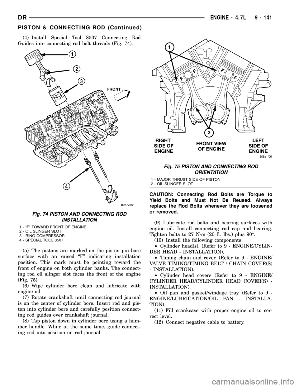
(4) Install Special Tool 8507 Connecting Rod
Guides into connecting rod bolt threads (Fig. 74).
(5) The pistons are marked on the piston pin bore
surface with an raised ªFº indicating installation
position. This mark must be pointing toward the
front of engine on both cylinder banks. The connect-
ing rod oil slinger slot faces the front of the engine
(Fig. 75).
(6) Wipe cylinder bore clean and lubricate with
engine oil.
(7) Rotate crankshaft until connecting rod journal
is on the center of cylinder bore. Insert rod and pis-
ton into cylinder bore and carefully position connect-
ing rod guides over crankshaft journal.
(8) Tap piston down in cylinder bore using a ham-
mer handle. While at the same time, guide connect-
ing rod into position on rod journal.CAUTION: Connecting Rod Bolts are Torque to
Yield Bolts and Must Not Be Reused. Always
replace the Rod Bolts whenever they are loosened
or removed.
(9) Lubricate rod bolts and bearing surfaces with
engine oil. Install connecting rod cap and bearing.
Tighten bolts to 27 N´m (20 ft. lbs.) plus 90É.
(10) Install the following components:
²Cylinder head(s). (Refer to 9 - ENGINE/CYLIN-
DER HEAD - INSTALLATION).
²Timing chain and cover. (Refer to 9 - ENGINE/
VALVE TIMING/TIMING BELT / CHAIN COVER(S)
- INSTALLATION).
²Cylinder head covers (Refer to 9 - ENGINE/
CYLINDER HEAD/CYLINDER HEAD COVER(S) -
INSTALLATION).
²Oil pan and gasket/windage tray. (Refer to 9 -
ENGINE/LUBRICATION/OIL PAN - INSTALLA-
TION).
(11) Fill crankcase with proper engine oil to cor-
rect level.
(12) Connect negative cable to battery.
Fig. 74 PISTON AND CONNECTING ROD
INSTALLATION
1 - ªFº TOWARD FRONT OF ENGINE
2 - OIL SLINGER SLOT
3 - RING COMPRESSOR
4 - SPECIAL TOOL 8507
Fig. 75 PISTON AND CONNECTING ROD
ORIENTATION
1 - MAJOR THRUST SIDE OF PISTON
2 - OIL SLINGER SLOT
DRENGINE - 4.7L 9 - 141
PISTON & CONNECTING ROD (Continued)
Page 1366 of 2627
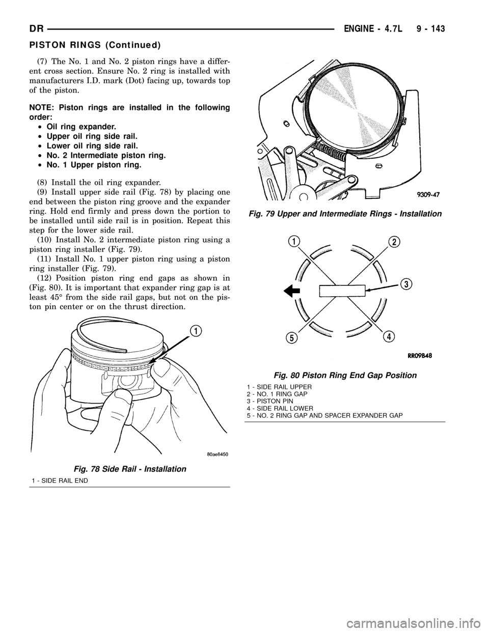
(7) The No. 1 and No. 2 piston rings have a differ-
ent cross section. Ensure No. 2 ring is installed with
manufacturers I.D. mark (Dot) facing up, towards top
of the piston.
NOTE: Piston rings are installed in the following
order:
²Oil ring expander.
²Upper oil ring side rail.
²Lower oil ring side rail.
²No. 2 Intermediate piston ring.
²No. 1 Upper piston ring.
(8) Install the oil ring expander.
(9) Install upper side rail (Fig. 78) by placing one
end between the piston ring groove and the expander
ring. Hold end firmly and press down the portion to
be installed until side rail is in position. Repeat this
step for the lower side rail.
(10) Install No. 2 intermediate piston ring using a
piston ring installer (Fig. 79).
(11) Install No. 1 upper piston ring using a piston
ring installer (Fig. 79).
(12) Position piston ring end gaps as shown in
(Fig. 80). It is important that expander ring gap is at
least 45É from the side rail gaps, but not on the pis-
ton pin center or on the thrust direction.
Fig. 78 Side Rail - Installation
1 - SIDE RAIL END
Fig. 79 Upper and Intermediate Rings - Installation
Fig. 80 Piston Ring End Gap Position
1 - SIDE RAIL UPPER
2 - NO. 1 RING GAP
3 - PISTON PIN
4 - SIDE RAIL LOWER
5 - NO. 2 RING GAP AND SPACER EXPANDER GAP
DRENGINE - 4.7L 9 - 143
PISTON RINGS (Continued)
Page 1374 of 2627
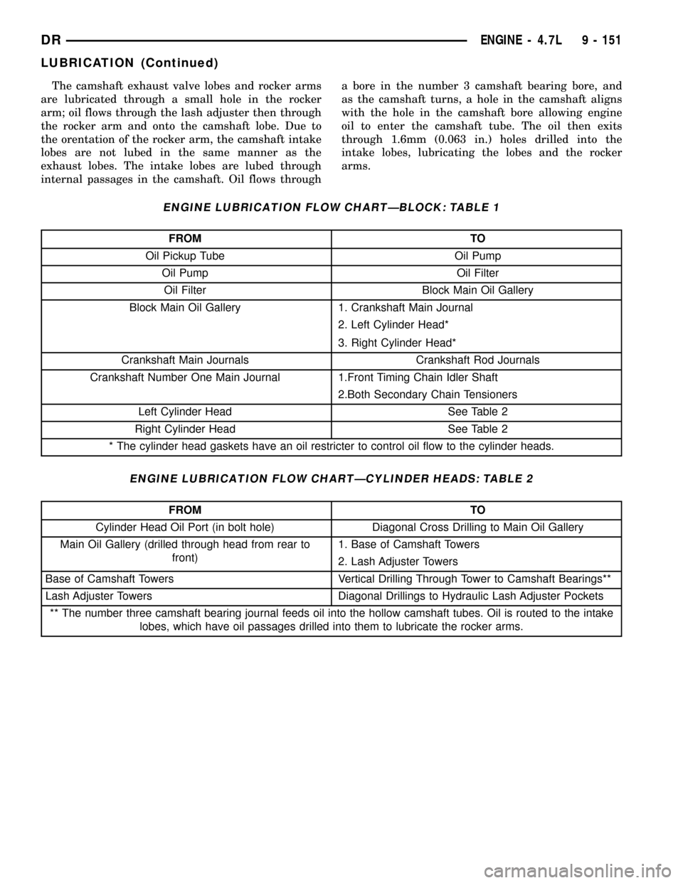
The camshaft exhaust valve lobes and rocker arms
are lubricated through a small hole in the rocker
arm; oil flows through the lash adjuster then through
the rocker arm and onto the camshaft lobe. Due to
the orentation of the rocker arm, the camshaft intake
lobes are not lubed in the same manner as the
exhaust lobes. The intake lobes are lubed through
internal passages in the camshaft. Oil flows througha bore in the number 3 camshaft bearing bore, and
as the camshaft turns, a hole in the camshaft aligns
with the hole in the camshaft bore allowing engine
oil to enter the camshaft tube. The oil then exits
through 1.6mm (0.063 in.) holes drilled into the
intake lobes, lubricating the lobes and the rocker
arms.
ENGINE LUBRICATION FLOW CHARTÐBLOCK: TABLE 1
FROM TO
Oil Pickup Tube Oil Pump
Oil Pump Oil Filter
Oil Filter Block Main Oil Gallery
Block Main Oil Gallery 1. Crankshaft Main Journal
2. Left Cylinder Head*
3. Right Cylinder Head*
Crankshaft Main Journals Crankshaft Rod Journals
Crankshaft Number One Main Journal 1.Front Timing Chain Idler Shaft
2.Both Secondary Chain Tensioners
Left Cylinder Head See Table 2
Right Cylinder Head See Table 2
* The cylinder head gaskets have an oil restricter to control oil flow to the cylinder heads.
ENGINE LUBRICATION FLOW CHARTÐCYLINDER HEADS: TABLE 2
FROM TO
Cylinder Head Oil Port (in bolt hole) Diagonal Cross Drilling to Main Oil Gallery
Main Oil Gallery (drilled through head from rear to
front)1. Base of Camshaft Towers
2. Lash Adjuster Towers
Base of Camshaft Towers Vertical Drilling Through Tower to Camshaft Bearings**
Lash Adjuster Towers Diagonal Drillings to Hydraulic Lash Adjuster Pockets
** The number three camshaft bearing journal feeds oil into the hollow camshaft tubes. Oil is routed to the intake
lobes, which have oil passages drilled into them to lubricate the rocker arms.
DRENGINE - 4.7L 9 - 151
LUBRICATION (Continued)
Page 1382 of 2627
INSTALLATION
(1) Position the oil pump onto the crankshaft and
install one oil pump retaining bolts.
(2) Position the primary timing chain tensioner
and install three retaining bolts.
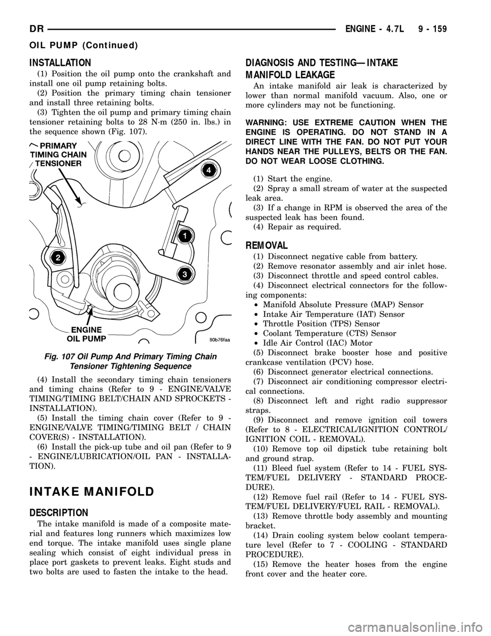
(3) Tighten the oil pump and primary timing chain
tensioner retaining bolts to 28 N´m (250 in. lbs.) in
the sequence shown (Fig. 107).
(4) Install the secondary timing chain tensioners
and timing chains (Refer to 9 - ENGINE/VALVE
TIMING/TIMING BELT/CHAIN AND SPROCKETS -
INSTALLATION).
(5) Install the timing chain cover (Refer to 9 -
ENGINE/VALVE TIMING/TIMING BELT / CHAIN
COVER(S) - INSTALLATION).
(6) Install the pick-up tube and oil pan (Refer to 9
- ENGINE/LUBRICATION/OIL PAN - INSTALLA-
TION).
INTAKE MANIFOLD
DESCRIPTION
The intake manifold is made of a composite mate-
rial and features long runners which maximizes low
end torque. The intake manifold uses single plane
sealing which consist of eight individual press in
place port gaskets to prevent leaks. Eight studs and
two bolts are used to fasten the intake to the head.
DIAGNOSIS AND TESTINGÐINTAKE
MANIFOLD LEAKAGE
An intake manifold air leak is characterized by
lower than normal manifold vacuum. Also, one or
more cylinders may not be functioning.
WARNING: USE EXTREME CAUTION WHEN THE
ENGINE IS OPERATING. DO NOT STAND IN A
DIRECT LINE WITH THE FAN. DO NOT PUT YOUR
HANDS NEAR THE PULLEYS, BELTS OR THE FAN.
DO NOT WEAR LOOSE CLOTHING.
(1) Start the engine.
(2) Spray a small stream of water at the suspected
leak area.
(3) If a change in RPM is observed the area of the
suspected leak has been found.
(4) Repair as required.
REMOVAL
(1) Disconnect negative cable from battery.
(2) Remove resonator assembly and air inlet hose.
(3) Disconnect throttle and speed control cables.
(4) Disconnect electrical connectors for the follow-
ing components:
²Manifold Absolute Pressure (MAP) Sensor
²Intake Air Temperature (IAT) Sensor
²Throttle Position (TPS) Sensor
²Coolant Temperature (CTS) Sensor
²Idle Air Control (IAC) Motor
(5) Disconnect brake booster hose and positive
crankcase ventilation (PCV) hose.
(6) Disconnect generator electrical connections.
(7) Disconnect air conditioning compressor electri-
cal connections.
(8) Disconnect left and right radio suppressor
straps.
(9) Disconnect and remove ignition coil towers
(Refer to 8 - ELECTRICAL/IGNITION CONTROL/
IGNITION COIL - REMOVAL).
(10) Remove top oil dipstick tube retaining bolt
and ground strap.
(11) Bleed fuel system (Refer to 14 - FUEL SYS-
TEM/FUEL DELIVERY - STANDARD PROCE-
DURE).
(12) Remove fuel rail (Refer to 14 - FUEL SYS-
TEM/FUEL DELIVERY/FUEL RAIL - REMOVAL).
(13) Remove throttle body assembly and mounting
bracket.
(14) Drain cooling system below coolant tempera-
ture level (Refer to 7 - COOLING - STANDARD
PROCEDURE).
(15) Remove the heater hoses from the engine
front cover and the heater core.
Fig. 107 Oil Pump And Primary Timing Chain
Tensioner Tightening Sequence
DRENGINE - 4.7L 9 - 159
OIL PUMP (Continued)
Page 1383 of 2627
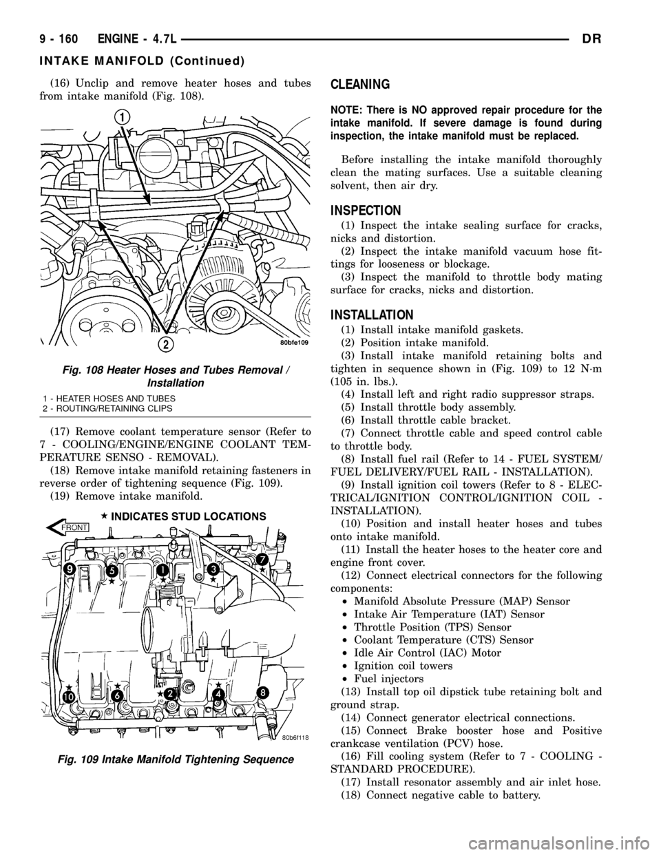
(16) Unclip and remove heater hoses and tubes
from intake manifold (Fig. 108).
(17) Remove coolant temperature sensor (Refer to
7 - COOLING/ENGINE/ENGINE COOLANT TEM-
PERATURE SENSO - REMOVAL).
(18) Remove intake manifold retaining fasteners in
reverse order of tightening sequence (Fig. 109).
(19) Remove intake manifold.CLEANING
NOTE: There is NO approved repair procedure for the
intake manifold. If severe damage is found during
inspection, the intake manifold must be replaced.
Before installing the intake manifold thoroughly
clean the mating surfaces. Use a suitable cleaning
solvent, then air dry.
INSPECTION
(1) Inspect the intake sealing surface for cracks,
nicks and distortion.
(2) Inspect the intake manifold vacuum hose fit-
tings for looseness or blockage.
(3) Inspect the manifold to throttle body mating
surface for cracks, nicks and distortion.
INSTALLATION
(1) Install intake manifold gaskets.
(2) Position intake manifold.
(3) Install intake manifold retaining bolts and
tighten in sequence shown in (Fig. 109) to 12 N´m
(105 in. lbs.).
(4) Install left and right radio suppressor straps.
(5) Install throttle body assembly.
(6) Install throttle cable bracket.
(7) Connect throttle cable and speed control cable
to throttle body.
(8) Install fuel rail (Refer to 14 - FUEL SYSTEM/
FUEL DELIVERY/FUEL RAIL - INSTALLATION).
(9) Install ignition coil towers (Refer to 8 - ELEC-
TRICAL/IGNITION CONTROL/IGNITION COIL -
INSTALLATION).
(10) Position and install heater hoses and tubes
onto intake manifold.
(11) Install the heater hoses to the heater core and
engine front cover.
(12) Connect electrical connectors for the following
components:
²Manifold Absolute Pressure (MAP) Sensor
²Intake Air Temperature (IAT) Sensor
²Throttle Position (TPS) Sensor
²Coolant Temperature (CTS) Sensor
²Idle Air Control (IAC) Motor
²Ignition coil towers
²Fuel injectors
(13) Install top oil dipstick tube retaining bolt and
ground strap.
(14) Connect generator electrical connections.
(15) Connect Brake booster hose and Positive
crankcase ventilation (PCV) hose.
(16) Fill cooling system (Refer to 7 - COOLING -
STANDARD PROCEDURE).
(17) Install resonator assembly and air inlet hose.
(18) Connect negative cable to battery.
Fig. 108 Heater Hoses and Tubes Removal /
Installation
1 - HEATER HOSES AND TUBES
2 - ROUTING/RETAINING CLIPS
Fig. 109 Intake Manifold Tightening Sequence
9 - 160 ENGINE - 4.7LDR
INTAKE MANIFOLD (Continued)
Page 1413 of 2627
CONDITION POSSIBLE CAUSES CORRECTION
EXCESSIVE OIL CONSUMPTION OR
SPARK PLUGS OIL FOULED1. CCV System malfunction 1. (Refer to 25 - EMISSIONS
CONTROL/EVAPORATIVE
EMISSIONS - DESCRIPTION) for
correct operation
2. Defective valve stem seal(s) 2. Repair or replace seal(s)
3. Worn or broken piston rings 3. Hone cylinder bores. Install new
rings
4. Scuffed pistons/cylinder walls 4. Hone cylinder bores and replace
pistons as required
5. Carbon in oil control ring groove 5. Remove rings and de-carbon piston
6. Worn valve guides 6. Inspect/replace valve guides as
necessary
7. Piston rings fitted too tightly in
grooves7. Remove rings and check ring end
gap and side clearance. Replace if
necessary
STANDARD PROCEDURE
STANDARD PROCEDURE - REPAIR DAMAGED
OR WORN THREADS
CAUTION: Be sure that the tapped holes maintain
the original center line.
Damaged or worn threads can be repaired. Essen-
tially, this repair consists of:
²Drilling out worn or damaged threads.
²Tapping the hole with a special Heli-Coil Tap, or
equivalent.
²Installing an insert into the tapped hole to bring
the hole back to its original thread size.
STANDARD PROCEDUREÐHYDROSTATIC
LOCK
CAUTION: DO NOT use the starter motor to rotate
the crankshaft. Severe damage could occur.
When an engine is suspected of hydrostatic lock
(regardless of what caused the problem), follow the
steps below.
(1) Perform the Fuel Pressure Release Procedure
(Refer to 14 - FUEL SYSTEM/FUEL DELIVERY -
STANDARD PROCEDURE).
(2) Disconnect the negative cable(s) from the bat-
tery.
(3) Inspect air cleaner, induction system, and
intake manifold to ensure system is dry and clear of
foreign material.
(4) Place a shop towel around the spark plugs to
catch any fluid that may possibly be under pressure
in the cylinder head. Remove the spark plugs.(5) With all spark plugs removed, rotate the crank-
shaft using a breaker bar and socket.
(6) Identify the fluid in the cylinders (coolant, fuel,
oil, etc.).
(7) Be sure all fluid has been removed from the
cylinders.
(8) Repair engine or components as necessary to
prevent this problem from occurring again.
(9) Squirt a small amount of engine oil into the
cylinders to lubricate the walls. This will prevent
damage on restart.
(10) Install new spark plugs. Tighten the spark
plugs to 41 N´m (30 ft. lbs.) torque.
(11) Drain engine oil. Remove and discard the oil
filter.
(12) Install the drain plug. Tighten the plug to 34
N´m (25 ft. lbs.) torque.
(13) Install a new oil filter.
(14) Fill engine crankcase with the specified
amount and grade of oil. (Refer to LUBRICATION &
MAINTENANCE - SPECIFICATIONS).
(15) Connect the negative cable(s) to the battery.
(16) Start the engine and check for any leaks.
REMOVAL
(1) Perform the Fuel System Pressure Release pro-
cedure (Refer to 14 - FUEL SYSTEM/FUEL DELIV-
ERY - STANDARD PROCEDURE).
(2) Disconnect the battery negative cable.
(3) Remove the air cleaner resonator and duct
work as an assembly.
(4) Drain cooling system (Refer to 7 - COOLING -
STANDARD PROCEDURE).
(5) Remove the accessory drive belt (Refer to 7 -
COOLING/ACCESSORY DRIVE/DRIVE BELTS -
REMOVAL).
9 - 190 ENGINE - 5.7LDR
ENGINE - 5.7L (Continued)
Page 1435 of 2627
(5) Piston installation into the cylinder bore
requires slightly more pressure than that required
for non-coated pistons. The bonded coating on the
piston will give the appearance of a line-to-line fit
with the cylinder bore.
REMOVAL
(1) Disconnect negative cable from battery.
(2) Remove the following components:
²Oil pan and gasket/windage tray (Refer to 9 -
ENGINE/LUBRICATION/OIL PAN - REMOVAL).
²Cylinder head covers (Refer to 9 - ENGINE/
CYLINDER HEAD/CYLINDER HEAD COVER(S) -
REMOVAL) and (Refer to 9 - ENGINE/CYLINDER
HEAD/CYLINDER HEAD COVER(S) - REMOVAL).
²Timing chain cover (Refer to 9 - ENGINE/
VALVE TIMING/TIMING BELT / CHAIN COVER(S)
- REMOVAL).
²Cylinder head(s) (Refer to 9 - ENGINE/CYLIN-
DER HEAD - REMOVAL) and (Refer to 9 - ENGINE/
CYLINDER HEAD - REMOVAL).
(3) If necessary, remove top ridge of cylinder bores
with a reliable ridge reamer before removing pistons
from cylinder block.Be sure to keep tops of pis-
tons covered during this operation.Pistons and
connecting rods must be removed from top of cylinder
block. When removing piston and connecting rod
assemblies from the engine, rotate crankshaft so the
each connecting rod is centered in cylinder bore.CAUTION: DO NOT use a number stamp or a punch
to mark connecting rods or caps, as damage to
connecting rods could occur
NOTE: Connecting rods and bearing caps are not
interchangeable and should be marked before
removing to ensure correct reassembly.
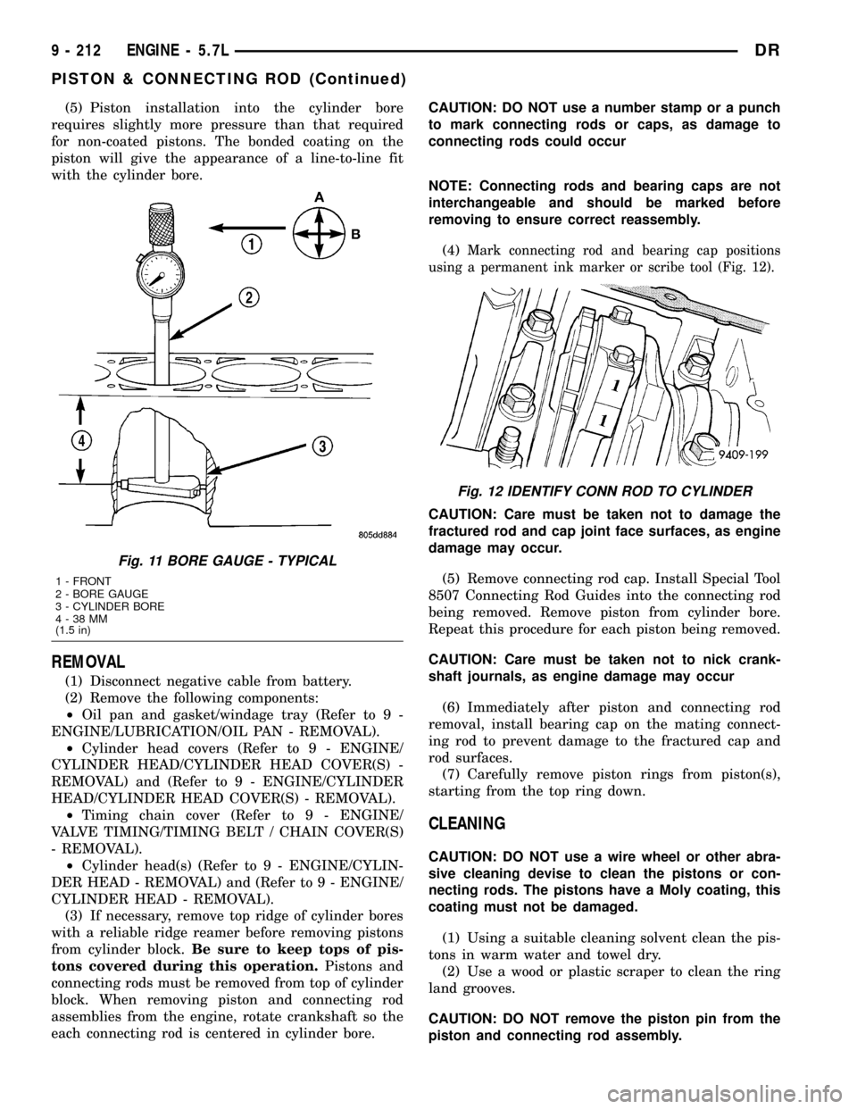
(4)
Mark connecting rod and bearing cap positions
using a permanent ink marker or scribe tool (Fig. 12).
CAUTION: Care must be taken not to damage the
fractured rod and cap joint face surfaces, as engine
damage may occur.
(5) Remove connecting rod cap. Install Special Tool
8507 Connecting Rod Guides into the connecting rod
being removed. Remove piston from cylinder bore.
Repeat this procedure for each piston being removed.
CAUTION: Care must be taken not to nick crank-
shaft journals, as engine damage may occur
(6) Immediately after piston and connecting rod
removal, install bearing cap on the mating connect-
ing rod to prevent damage to the fractured cap and
rod surfaces.
(7) Carefully remove piston rings from piston(s),
starting from the top ring down.
CLEANING
CAUTION: DO NOT use a wire wheel or other abra-
sive cleaning devise to clean the pistons or con-
necting rods. The pistons have a Moly coating, this
coating must not be damaged.
(1) Using a suitable cleaning solvent clean the pis-
tons in warm water and towel dry.
(2) Use a wood or plastic scraper to clean the ring
land grooves.
CAUTION: DO NOT remove the piston pin from the
piston and connecting rod assembly.
Fig. 11 BORE GAUGE - TYPICAL
1 - FRONT
2 - BORE GAUGE
3 - CYLINDER BORE
4-38MM
(1.5 in)
Fig. 12 IDENTIFY CONN ROD TO CYLINDER
9 - 212 ENGINE - 5.7LDR
PISTON & CONNECTING ROD (Continued)
Page 1436 of 2627
INSPECTION
Check the connecting rod journal for excessive
wear, taper and scoring (Refer to 9 - ENGINE/EN-
GINE BLOCK/CONNECTING ROD BEARINGS -
STANDARD PROCEDURE).
Check the connecting rod for signs of twist or bend-
ing.
Check the piston for taper and elliptical shape
before it is fitted into the cylinder bore (Refer to 9 -
ENGINE/ENGINE BLOCK/PISTON & CONNECT-
ING ROD - STANDARD PROCEDURE).
Check the piston for scoring, or scraping marks in
the piston skirts. Check the ring lands for cracks
and/or deterioration.
INSTALLATION
(1) Before installing piston and connecting rod
assemblies into the bore, install the piston rings(Re-
fer to 9 - ENGINE/ENGINE BLOCK/PISTON RINGS
- STANDARD PROCEDURE).
(2) Immerse the piston head and rings in clean
engine oil. Position a ring compressor over the piston
and rings. Tighten ring compressor.Ensure posi-
tion of rings do not change during this opera-
tion.
(3) Position bearing onto connecting rod. Lubricate
bearing surface with clean engine oil.
(4) Install Special Tool 8507 Connecting Rod
Guides into connecting rod bolt threads.
(5) The pistons are marked on the piston pin bore
surface with an raised ªFº or arrow on top of piston
indicating installation position. This mark must be
pointing toward the front of engine on both cylinder
banks.
(6) Wipe cylinder bore clean and lubricate with
engine oil.
(7) Rotate crankshaft until connecting rod journal
is on the center of cylinder bore. Insert rod and pis-
ton into cylinder bore and carefully position connect-
ing rod guides over crankshaft journal.
(8) Tap piston down in cylinder bore using a ham-
mer handle. While at the same time, guide connect-
ing rod into position on rod journal.
CAUTION: Connecting Rod Bolts are Torque to
Yield Bolts and Must Not Be Reused. Always
replace the Rod Bolts whenever they are loosened
or removed.
(9) Lubricate rod bolts and bearing surfaces with
engine oil. Install connecting rod cap and bearing.
Tighten bolts to 21 N´m (15 ft. lbs.) plus a 90É turn.
(10) Install the following components:
²Cylinder head(s). (Refer to 9 - ENGINE/CYLIN-
DER HEAD - INSTALLATION).²Cylinder head covers (Refer to 9 - ENGINE/
CYLINDER HEAD/CYLINDER HEAD COVER(S) -
INSTALLATION).
²Install the intake manifold.
²Oil pan and gasket/windage tray. (Refer to 9 -
ENGINE/LUBRICATION/OIL PAN - INSTALLA-
TION).
(11) Fill crankcase with proper engine oil to cor-
rect level.
(12) Connect negative cable to battery.
PISTON RINGS
STANDARD PROCEDURE - PISTON RING
FITTING
Before reinstalling used rings or installing new
rings, the ring clearances must be checked.
(1) Wipe the cylinder bore clean.
(2) Insert the ring in the cylinder bore.
NOTE: The ring gap measurement must be made
with the ring positioned at least 12mm (0.50 inch.)
from bottom of cylinder bore.
(3) Using a piston, to ensure that the ring is
squared in the cylinder bore, slide the ring downward
into the cylinder.
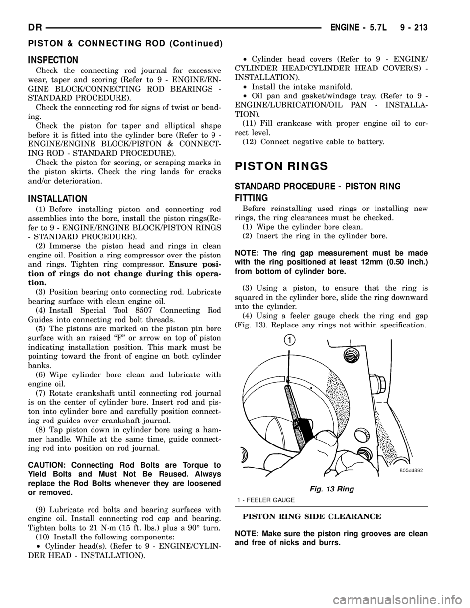
(4) Using a feeler gauge check the ring end gap
(Fig. 13). Replace any rings not within specification.
PISTON RING SIDE CLEARANCE
NOTE: Make sure the piston ring grooves are clean
and free of nicks and burrs.
Fig. 13 Ring
1 - FEELER GAUGE
DRENGINE - 5.7L 9 - 213
PISTON & CONNECTING ROD (Continued)