1998 DODGE RAM 1500 tow
[x] Cancel search: towPage 1276 of 2627
²Timing chain and cover. (Refer to 9 - ENGINE/
VALVE TIMING/TIMING BELT / CHAIN COVER(S)
- INSTALLATION).
²Cylinder head covers (Refer to 9 - ENGINE/
CYLINDER HEAD/CYLINDER HEAD COVER(S) -
INSTALLATION).
²Oil pan and gasket/windage tray. (Refer to 9 -
ENGINE/LUBRICATION/OIL PAN - INSTALLA-
TION).
(11) Fill crankcase with proper engine oil to cor-
rect level.
(12) Connect negative cable to battery.
PISTON RINGS
STANDARD PROCEDURE - PISTON RING
FITTING
Before reinstalling used rings or installing new
rings, the ring clearances must be checked.
(1) Wipe the cylinder bore clean.
(2) Insert the ring in the cylinder bore.NOTE: The ring gap measurement must be made
with the ring positioned at least 12mm (0.50 inch.)
from bottom of cylinder bore.
(3) Using a piston, to ensure that the ring is
squared in the cylinder bore, slide the ring downward
into the cylinder.
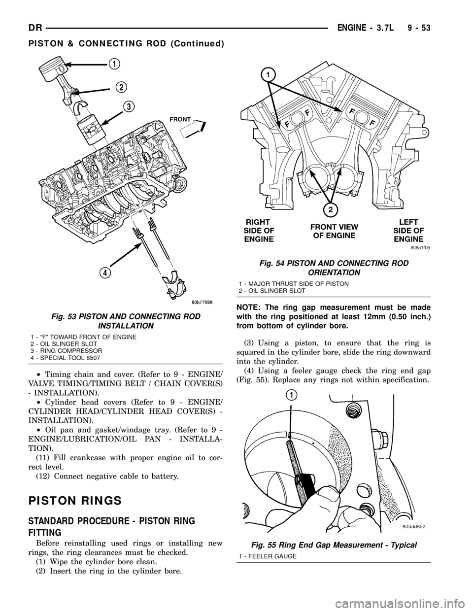
(4) Using a feeler gauge check the ring end gap
(Fig. 55). Replace any rings not within specification.
Fig. 53 PISTON AND CONNECTING ROD
INSTALLATION
1 - ªFº TOWARD FRONT OF ENGINE
2 - OIL SLINGER SLOT
3 - RING COMPRESSOR
4 - SPECIAL TOOL 8507
Fig. 54 PISTON AND CONNECTING ROD
ORIENTATION
1 - MAJOR THRUST SIDE OF PISTON
2 - OIL SLINGER SLOT
Fig. 55 Ring End Gap Measurement - Typical
1 - FEELER GAUGE
DRENGINE - 3.7L 9 - 53
PISTON & CONNECTING ROD (Continued)
Page 1277 of 2627
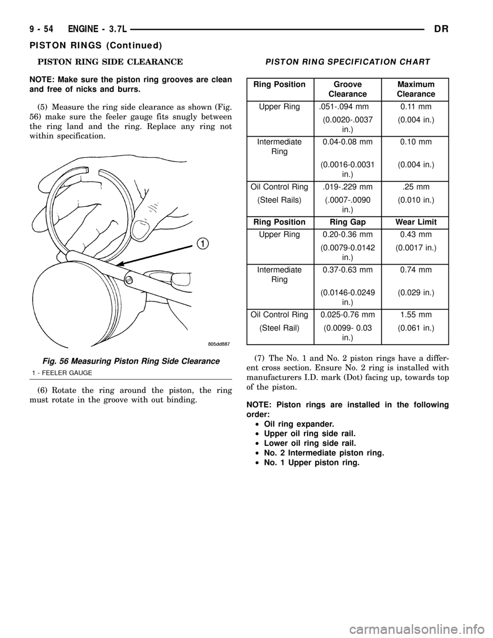
PISTON RING SIDE CLEARANCE
NOTE: Make sure the piston ring grooves are clean
and free of nicks and burrs.
(5) Measure the ring side clearance as shown (Fig.
56) make sure the feeler gauge fits snugly between
the ring land and the ring. Replace any ring not
within specification.
(6) Rotate the ring around the piston, the ring
must rotate in the groove with out binding.PISTON RING SPECIFICATION CHART
Ring Position Groove
ClearanceMaximum
Clearance
Upper Ring .051-.094 mm 0.11 mm
(0.0020-.0037
in.)(0.004 in.)
Intermediate
Ring0.04-0.08 mm 0.10 mm
(0.0016-0.0031
in.)(0.004 in.)
Oil Control Ring .019-.229 mm .25 mm
(Steel Rails) (.0007-.0090
in.)(0.010 in.)
Ring Position Ring Gap Wear Limit
Upper Ring 0.20-0.36 mm 0.43 mm
(0.0079-0.0142
in.)(0.0017 in.)
Intermediate
Ring0.37-0.63 mm 0.74 mm
(0.0146-0.0249
in.)(0.029 in.)
Oil Control Ring 0.025-0.76 mm 1.55 mm
(Steel Rail) (0.0099- 0.03
in.)(0.061 in.)
(7) The No. 1 and No. 2 piston rings have a differ-
ent cross section. Ensure No. 2 ring is installed with
manufacturers I.D. mark (Dot) facing up, towards top
of the piston.
NOTE: Piston rings are installed in the following
order:
²Oil ring expander.
²Upper oil ring side rail.
²Lower oil ring side rail.
²No. 2 Intermediate piston ring.
²No. 1 Upper piston ring.
Fig. 56 Measuring Piston Ring Side Clearance
1 - FEELER GAUGE
9 - 54 ENGINE - 3.7LDR
PISTON RINGS (Continued)
Page 1285 of 2627
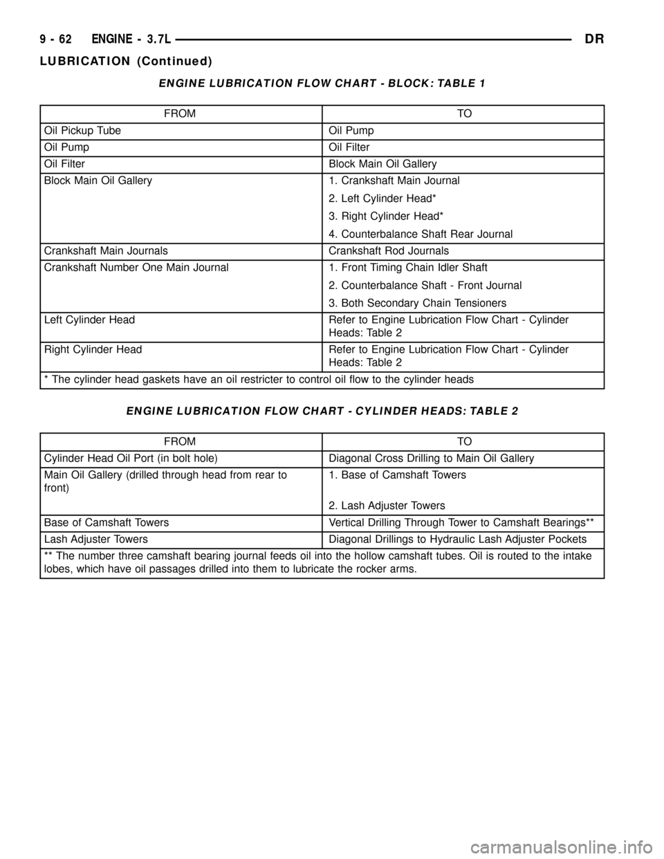
ENGINE LUBRICATION FLOW CHART - BLOCK: TABLE 1
FROM TO
Oil Pickup Tube Oil Pump
Oil Pump Oil Filter
Oil Filter Block Main Oil Gallery
Block Main Oil Gallery 1. Crankshaft Main Journal
2. Left Cylinder Head*
3. Right Cylinder Head*
4. Counterbalance Shaft Rear Journal
Crankshaft Main Journals Crankshaft Rod Journals
Crankshaft Number One Main Journal 1. Front Timing Chain Idler Shaft
2. Counterbalance Shaft - Front Journal
3. Both Secondary Chain Tensioners
Left Cylinder Head Refer to Engine Lubrication Flow Chart - Cylinder
Heads: Table 2
Right Cylinder Head Refer to Engine Lubrication Flow Chart - Cylinder
Heads: Table 2
* The cylinder head gaskets have an oil restricter to control oil flow to the cylinder heads
ENGINE LUBRICATION FLOW CHART - CYLINDER HEADS: TABLE 2
FROM TO
Cylinder Head Oil Port (in bolt hole) Diagonal Cross Drilling to Main Oil Gallery
Main Oil Gallery (drilled through head from rear to
front)1. Base of Camshaft Towers
2. Lash Adjuster Towers
Base of Camshaft Towers Vertical Drilling Through Tower to Camshaft Bearings**
Lash Adjuster Towers Diagonal Drillings to Hydraulic Lash Adjuster Pockets
** The number three camshaft bearing journal feeds oil into the hollow camshaft tubes. Oil is routed to the intake
lobes, which have oil passages drilled into them to lubricate the rocker arms.
9 - 62 ENGINE - 3.7LDR
LUBRICATION (Continued)
Page 1296 of 2627
(1) Start the engine.
(2) Spray a small stream of water (spray bottle) at
the suspected leak area.
(3) If engine RPM'S change, the area of the sus-
pected leak has been found.
(4) Repair as required.
REMOVAL
(1) Disconnect negative cable from battery.
(2) Remove resonator assembly and air inlet hose.
(3) Disconnect throttle and speed control cables.
(4) Disconnect electrical connectors for the follow-
ing components: Refer to FUEL SYSTEM for compo-
nent locations.
²Manifold Absolute Pressure (MAP) Sensor
²Intake Air Temperature (IAT) Sensor
²Throttle Position (TPS) Sensor
²Coolant Temperature (CTS) Sensor
²Idle Air Control (IAC) Motor
(5) Disconnect vapor purge hose, brake booster
hose, speed control servo hose, positive crankcase
ventilation (PCV) hose.
(6) Disconnect generator electrical connections.
(7) Disconnect air conditioning compressor electri-
cal connections.
(8) Disconnect left and right radio suppressor
straps.
(9) Disconnect and remove ignition coil towers.
(10) Remove top oil dipstick tube retaining bolt
and ground strap.
(11) Bleed fuel system (Refer to 14 - FUEL SYS-
TEM/FUEL DELIVERY - STANDARD PROCE-
DURE).
(12) Remove fuel rail.
(13) Remove throttle body assembly and mounting
bracket.
(14) Drain cooling system below coolant tempera-
ture level (Refer to 7 - COOLING - STANDARD
PROCEDURE).
(15) Remove the heater hoses from the engine
front cover and the heater core.
(16) Unclip and remove heater hoses and tubes
from intake manifold.
(17) Remove coolant temperature sensor (Refer to
7 - COOLING/ENGINE/ENGINE COOLANT TEMP
SENSOR - REMOVAL).
(18) Remove intake manifold retaining fasteners in
reverse order of tightening sequence.
(19) Remove intake manifold.
INSTALLATION
(1) Install intake manifold gaskets.
(2) Install intake manifold.
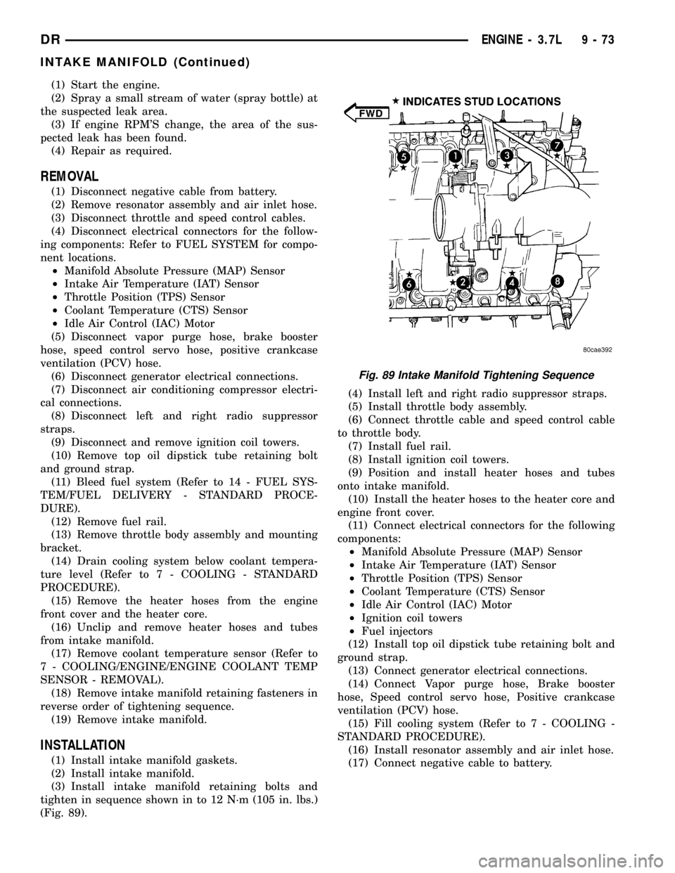
(3) Install intake manifold retaining bolts and
tighten in sequence shown in to 12 N´m (105 in. lbs.)
(Fig. 89).(4) Install left and right radio suppressor straps.
(5) Install throttle body assembly.
(6) Connect throttle cable and speed control cable
to throttle body.
(7) Install fuel rail.
(8) Install ignition coil towers.
(9) Position and install heater hoses and tubes
onto intake manifold.
(10) Install the heater hoses to the heater core and
engine front cover.
(11) Connect electrical connectors for the following
components:
²Manifold Absolute Pressure (MAP) Sensor
²Intake Air Temperature (IAT) Sensor
²Throttle Position (TPS) Sensor
²Coolant Temperature (CTS) Sensor
²Idle Air Control (IAC) Motor
²Ignition coil towers
²Fuel injectors
(12) Install top oil dipstick tube retaining bolt and
ground strap.
(13) Connect generator electrical connections.
(14) Connect Vapor purge hose, Brake booster
hose, Speed control servo hose, Positive crankcase
ventilation (PCV) hose.
(15) Fill cooling system (Refer to 7 - COOLING -
STANDARD PROCEDURE).
(16) Install resonator assembly and air inlet hose.
(17) Connect negative cable to battery.
Fig. 89 Intake Manifold Tightening Sequence
DRENGINE - 3.7L 9 - 73
INTAKE MANIFOLD (Continued)
Page 1318 of 2627
to one gasket surface. Be certain the material sur-
rounds each mounting hole. Excess material can eas-
ily be wiped off. Components should be torqued in
place within 15 minutes. The use of a locating dowel
is recommended during assembly to prevent smear-
ing material off the location.
MopartEngine RTV GEN II or ATF RTV gasket
material should be applied in a continuous bead
approximately 3 mm (0.120 in.) in diameter. All
mounting holes must be circled. For corner sealing, a
3.17 or 6.35 mm (1/8 or 1/4 in.) drop is placed in the
center of the gasket contact area. Uncured sealant
may be removed with a shop towel. Components
should be torqued in place while the sealant is still
wet to the touch (within 10 minutes). The usage of a
locating dowel is recommended during assembly to
prevent smearing material off the location.
MopartGasket Sealant in an aerosol can should be
applied using a thin, even coat sprayed completely
over both surfaces to be joined, and both sides of a
gasket. Then proceed with assembly. Material in a
can w/applicator can be brushed on evenly over the
sealing surfaces. Material in an aerosol can should be
used on engines with multi-layer steel gaskets.
REMOVAL
NOTE: This procedure applies to both the 4X2 and
4X4 vehicles, steps that apply to the 4X4 vehicle
only, are identified.
(1) Disconnect the battery negative and positive
cables.
(2) Remove the battery and the battery tray.
(3) Raise vehicle on hoist.
(4) Remove exhaust crossover pipe from exhaust
manifolds.
(5)4X4 vehiclesDisconnect axle vent tube from
left side engine mount.
(6) Remove the through bolt retaining nut and bolt
from both the left and right side engine mounts.
(7)4X4 vehiclesRemove locknut from left and
right side engine mount brackets.
(8) Disconnect two ground straps from the lower
left hand side and one ground strap from the lower
right hand side of the engine.
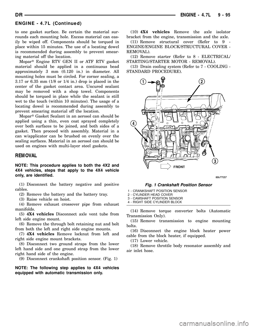
(9) Disconnect crankshaft position sensor. (Fig. 1)
NOTE: The following step applies to 4X4 vehicles
equipped with automatic transmission only.(10)4X4 vehiclesRemove the axle isolator
bracket from the engine, transmission and the axle.
(11) Remove structural cover (Refer to 9 -
ENGINE/ENGINE BLOCK/STRUCTURAL COVER -
REMOVAL).
(12) Remove starter (Refer to 8 - ELECTRICAL/
STARTING/STARTER MOTOR - REMOVAL).
(13) Drain cooling system (Refer to 7 - COOLING -
STANDARD PROCEDURE).
(14) Remove torque converter bolts (Automatic
Transmission Only).
(15) Remove transmission to engine mounting
bolts.
(16) Disconnect the engine block heater power
cable from the block heater, if equipped.
(17) Lower vehicle.
(18) Remove throttle body resonator assembly and
air inlet hose.
Fig. 1 Crankshaft Position Sensor
1 - CRANKSHAFT POSITION SENSOR
2 - CYLINDER HEAD COVER
3 - CAMSHAFT POSITION SENSOR
4 - RIGHT SIDE CYLINDER BLOCK
DRENGINE - 4.7L 9 - 95
ENGINE - 4.7L (Continued)
Page 1351 of 2627
ENGINE BLOCK
DESCRIPTION
The cylinder block is made of cast iron. The block
is a closed deck design with the left bank forward. To
provide high rigidity and improved NVH an
enhanced compacted graphite bedplate is bolted to
the block. The block design allows coolant flow
between the cylinders bores, and an internal coolant
bypass to a single poppet inlet thermostat is included
in the cast aluminum front cover.
STANDARD PROCEDURE - CYLINDER BORE
HONING
Before honing, stuff plenty of clean shop towels
under the bores and over the crankshaft to keep
abrasive materials from entering the crankshaft
area.
(1) Used carefully, the Cylinder Bore Sizing Hone
C-823, equipped with 220 grit stones, is the best tool
for this job. In addition to deglazing, it will reduce
taper and out-of-round, as well as removing light
scuffing, scoring and scratches. Usually, a few strokes
will clean up a bore and maintain the required lim-
its.
CAUTION: DO NOT use rigid type hones to remove
cylinder wall glaze.
(2) Deglazing of the cylinder walls may be done if
the cylinder bore is straight and round. Use a cylin-
der surfacing hone, Honing Tool C-3501, equipped
with 280 grit stones (C-3501-3810). about 20-60
strokes, depending on the bore condition, will be suf-
ficient to provide a satisfactory surface. Using honing
oil C-3501-3880, or a light honing oil, available from
major oil distributors.
CAUTION: DO NOT use engine or transmission oil,
mineral spirits, or kerosene.
(3) Honing should be done by moving the hone up
and down fast enough to get a crosshatch pattern.
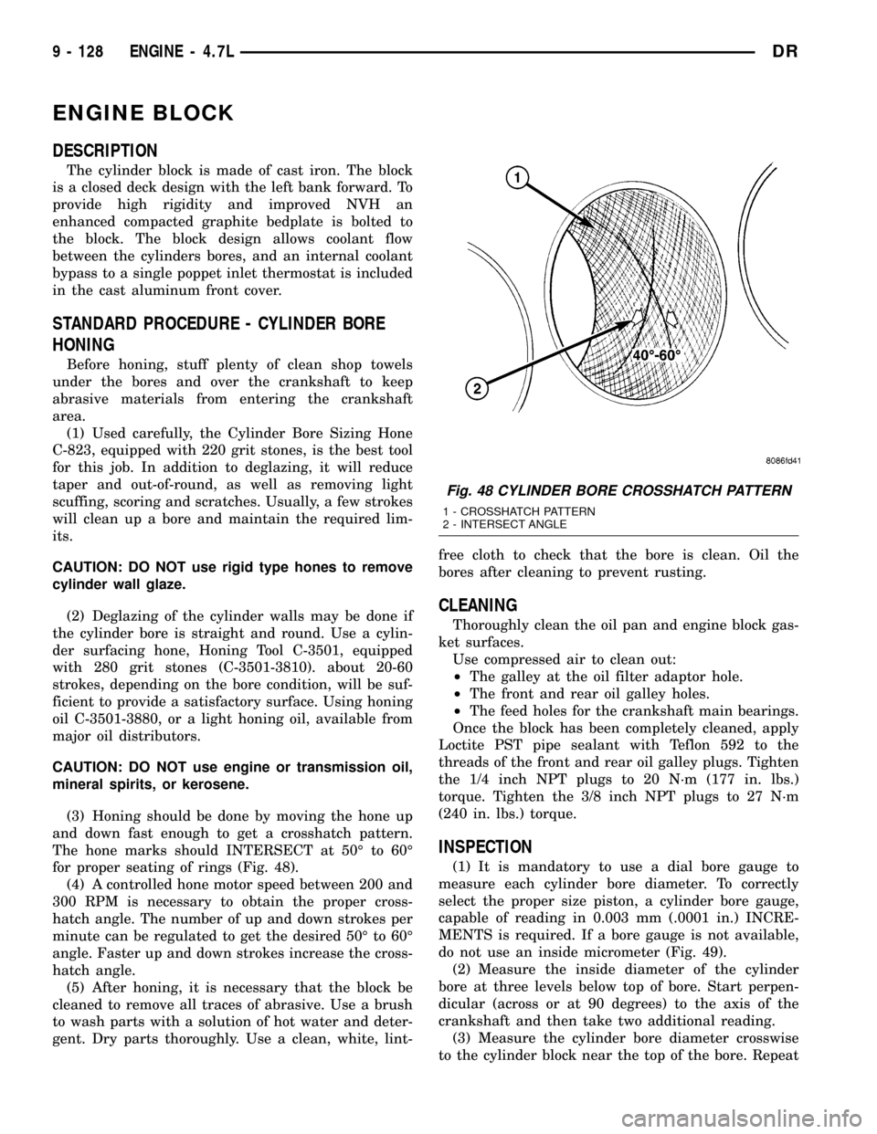
The hone marks should INTERSECT at 50É to 60É
for proper seating of rings (Fig. 48).
(4) A controlled hone motor speed between 200 and
300 RPM is necessary to obtain the proper cross-
hatch angle. The number of up and down strokes per
minute can be regulated to get the desired 50É to 60É
angle. Faster up and down strokes increase the cross-
hatch angle.
(5) After honing, it is necessary that the block be
cleaned to remove all traces of abrasive. Use a brush
to wash parts with a solution of hot water and deter-
gent. Dry parts thoroughly. Use a clean, white, lint-free cloth to check that the bore is clean. Oil the
bores after cleaning to prevent rusting.
CLEANING
Thoroughly clean the oil pan and engine block gas-
ket surfaces.
Use compressed air to clean out:
²The galley at the oil filter adaptor hole.
²The front and rear oil galley holes.
²The feed holes for the crankshaft main bearings.
Once the block has been completely cleaned, apply
Loctite PST pipe sealant with Teflon 592 to the
threads of the front and rear oil galley plugs. Tighten
the 1/4 inch NPT plugs to 20 N´m (177 in. lbs.)
torque. Tighten the 3/8 inch NPT plugs to 27 N´m
(240 in. lbs.) torque.
INSPECTION
(1) It is mandatory to use a dial bore gauge to
measure each cylinder bore diameter. To correctly
select the proper size piston, a cylinder bore gauge,
capable of reading in 0.003 mm (.0001 in.) INCRE-
MENTS is required. If a bore gauge is not available,
do not use an inside micrometer (Fig. 49).
(2) Measure the inside diameter of the cylinder
bore at three levels below top of bore. Start perpen-
dicular (across or at 90 degrees) to the axis of the
crankshaft and then take two additional reading.
(3) Measure the cylinder bore diameter crosswise
to the cylinder block near the top of the bore. Repeat
Fig. 48 CYLINDER BORE CROSSHATCH PATTERN
1 - CROSSHATCH PATTERN
2 - INTERSECT ANGLE
9 - 128 ENGINE - 4.7LDR
Page 1353 of 2627
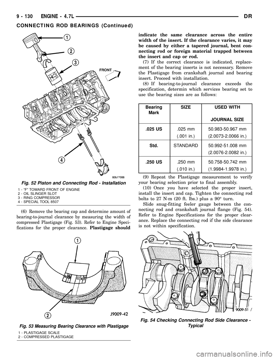
(6)Remove the bearing cap and determine amount of
bearing-to-journal clearance by measuring the width of
compressed Plastigage (Fig. 53). Refer to Engine Speci-
fications for the proper clearance.Plastigage shouldindicate the same clearance across the entire
width of the insert. If the clearance varies, it may
be caused by either a tapered journal, bent con-
necting rod or foreign material trapped between
the insert and cap or rod.
(7) If the correct clearance is indicated, replace-
ment of the bearing inserts is not necessary. Remove
the Plastigage from crankshaft journal and bearing
insert. Proceed with installation.
(8) If bearing-to-journal clearance exceeds the
specification, determin which services bearing set to
use the bearing sizes are as follows:
Bearing
MarkSIZE USED WITH
JOURNAL SIZE
.025 US.025 mm 50.983-50.967 mm
(.001 in.) (2.0073-2.0066 in.)
Std.STANDARD 50.992-51.008 mm
(2.0076-2.0082 in.)
.250 US.250 mm 50.758-50.742 mm
(.010 in.) (1.9984-1.9978 in.)
(9) Repeat the Plastigage measurement to verify
your bearing selection prior to final assembly.
(10) Once you have selected the proper insert,
install the insert and cap. Tighten the connecting rod
bolts to 27 N´m (20 ft. lbs.) plus a 90É turn.
Slide snug-fitting feeler gauge between the con-
necting rod and crankshaft journal flange (Fig. 54).
Refer to Engine Specifications for the proper clear-
ance. Replace the connecting rod if the side clearance
is not within specification.
Fig. 53 Measuring Bearing Clearance with Plastigage
1 - PLASTIGAGE SCALE
2 - COMPRESSED PLASTIGAGE
Fig. 52 Piston and Connecting Rod - Installation
1 - ªFº TOWARD FRONT OF ENGINE
2 - OIL SLINGER SLOT
3 - RING COMPRESSOR
4 - SPECIAL TOOL 8507
Fig. 54 Checking Connecting Rod Side Clearance -
Typical
9 - 130 ENGINE - 4.7LDR
CONNECTING ROD BEARINGS (Continued)
Page 1363 of 2627
tons covered during this operation.Pistons and
connecting rods must be removed from top of cylinder
block. When removing piston and connecting rod
assemblies from the engine, rotate crankshaft so the
each connecting rod is centered in cylinder bore.
CAUTION: DO NOT use a number stamp or a punch
to mark connecting rods or caps, as damage to
connecting rods could occur
NOTE: Connecting rods and bearing caps are not
interchangeable and should be marked before
removing to ensure correct reassembly.
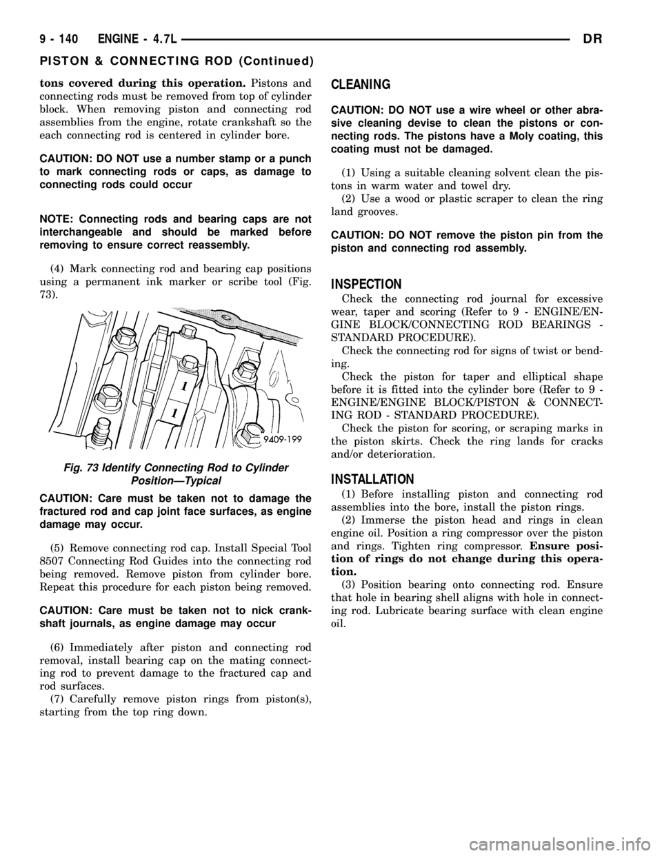
(4) Mark connecting rod and bearing cap positions
using a permanent ink marker or scribe tool (Fig.
73).
CAUTION: Care must be taken not to damage the
fractured rod and cap joint face surfaces, as engine
damage may occur.
(5) Remove connecting rod cap. Install Special Tool
8507 Connecting Rod Guides into the connecting rod
being removed. Remove piston from cylinder bore.
Repeat this procedure for each piston being removed.
CAUTION: Care must be taken not to nick crank-
shaft journals, as engine damage may occur
(6) Immediately after piston and connecting rod
removal, install bearing cap on the mating connect-
ing rod to prevent damage to the fractured cap and
rod surfaces.
(7) Carefully remove piston rings from piston(s),
starting from the top ring down.CLEANING
CAUTION: DO NOT use a wire wheel or other abra-
sive cleaning devise to clean the pistons or con-
necting rods. The pistons have a Moly coating, this
coating must not be damaged.
(1) Using a suitable cleaning solvent clean the pis-
tons in warm water and towel dry.
(2) Use a wood or plastic scraper to clean the ring
land grooves.
CAUTION: DO NOT remove the piston pin from the
piston and connecting rod assembly.
INSPECTION
Check the connecting rod journal for excessive
wear, taper and scoring (Refer to 9 - ENGINE/EN-
GINE BLOCK/CONNECTING ROD BEARINGS -
STANDARD PROCEDURE).
Check the connecting rod for signs of twist or bend-
ing.
Check the piston for taper and elliptical shape
before it is fitted into the cylinder bore (Refer to 9 -
ENGINE/ENGINE BLOCK/PISTON & CONNECT-
ING ROD - STANDARD PROCEDURE).
Check the piston for scoring, or scraping marks in
the piston skirts. Check the ring lands for cracks
and/or deterioration.
INSTALLATION
(1) Before installing piston and connecting rod
assemblies into the bore, install the piston rings.
(2) Immerse the piston head and rings in clean
engine oil. Position a ring compressor over the piston
and rings. Tighten ring compressor.Ensure posi-
tion of rings do not change during this opera-
tion.
(3) Position bearing onto connecting rod. Ensure
that hole in bearing shell aligns with hole in connect-
ing rod. Lubricate bearing surface with clean engine
oil.
Fig. 73 Identify Connecting Rod to Cylinder
PositionÐTypical
9 - 140 ENGINE - 4.7LDR
PISTON & CONNECTING ROD (Continued)