1998 DODGE RAM 1500 differential
[x] Cancel search: differentialPage 244 of 2627

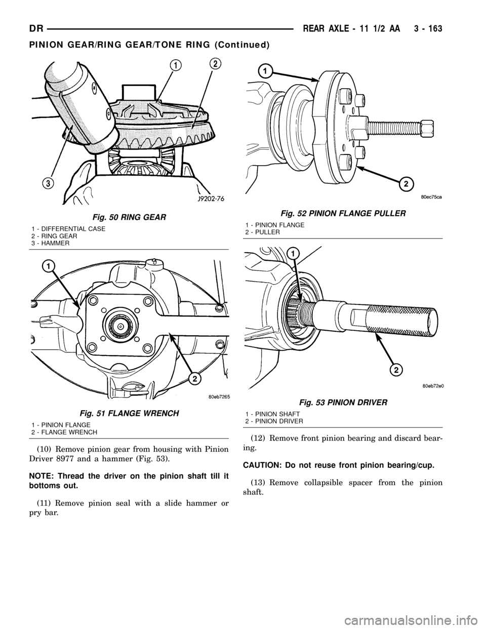
(10) Remove pinion gear from housing with Pinion
Driver 8977 and a hammer (Fig. 53).
NOTE: Thread the driver on the pinion shaft till it
bottoms out.
(11) Remove pinion seal with a slide hammer or
pry bar.(12) Remove front pinion bearing and discard bear-
ing.
CAUTION: Do not reuse front pinion bearing/cup.
(13) Remove collapsible spacer from the pinion
shaft.
Fig. 50 RING GEAR
1 - DIFFERENTIAL CASE
2 - RING GEAR
3 - HAMMER
Fig. 51 FLANGE WRENCH
1 - PINION FLANGE
2 - FLANGE WRENCH
Fig. 52 PINION FLANGE PULLER
1 - PINION FLANGE
2 - PULLER
Fig. 53 PINION DRIVER
1 - PINION SHAFT
2 - PINION DRIVER
DRREAR AXLE - 11 1/2 AA 3 - 163
PINION GEAR/RING GEAR/TONE RING (Continued)
Page 246 of 2627

(4) Install rear pinion bearing (Fig. 58) with
Installer D-389 and a press.
(5) Installnewcollapsible spacer (Fig. 59).
(6) Lubricate pinion and bearings.
(7) Install pinion into the housing and place front
pinion bearing onto the pinion shaft. Draw the pinionshaft into the front bearing with Installer 8981 (Fig.
60).
(8) Installnewpinion seal (Fig. 61) with Installer
8896 and Handle C-4171.
(9) Apply a light coat of teflon sealant to the pin-
ion flange splines.
(10) Hold pinion and lightly tap the pinion flange
onto the pinion, until a few threads are showing.
(11) Install pinion flange washer andnewpinion
nut.
(12) Hold pinion flange with Flange Wrench 8979
(Fig. 62) and tighten pinion nut until pinion end play
is taken up.
(13) Rotate pinion several times to seat bearings.
(14) Measure pinion rotating torque with an inch
pound torque wrench (Fig. 63). Tighten pinion nut in
small increments until pinion rotating torque is:
²New Pinion Bearings:1.7-2.8 N´m (15-25 in.
lbs.)
²Original Pinion Bearings:1.1-2.2 N´m (10-20
in. lbs.)
Fig. 58 REAR PINION BEARING
1 - PRESS
2 - INSTALLER
3 - PINION GEAR
4 - REAR PINION BEARING
Fig. 59 COLLAPSIBLE SPACER
1 - COLAPSIBLE SPACER
2 - PINION GEAR
3 - REAR PINION BEARING
Fig. 60 PINION GEAR INSTALLER
1 - INSTALLER
2 - DIFFERENTIAL HOUSING
Fig. 61 PINION SEAL INSTALLER
1 - HANDLE
2 - INSTALLER
DRREAR AXLE - 11 1/2 AA 3 - 165
PINION GEAR/RING GEAR/TONE RING (Continued)
Page 247 of 2627

(15) Rotate pinion several times then verify pinion
rotating torque again.
(16) Position the ring gear on differential case and
start twonewring gear bolts.
(17) Install the rest of thenewring gear bolts and
tighten them alternately to seat the ring gear.
(18) Torque ring gear bolts to 237 N´m (175 ft.
lbs.).
(19) If exciter ring was removed, position differen-
tial assembly on differential Plug 8965 (Fig. 64) and
place exciter ring on the differential case.
(20) Install the exciter ring on the differential case
evenly with a hammer and brass punch (Fig. 65).Drive the ring down until it is seated against the
ring gear.
CAUTION: Do not damage exciter ring teeth during
installation.
Fig. 62 FLANGE WRENCH
1 - FLANGE WRENCH
2 - PINION FLANGE
Fig. 63 PINION ROTATING TORQUE
1 - PINION FLANGE
2 - TORQUE WRENCH
Fig. 64 EXCITER RING
1 - EXCITER RING
2 - RING GEAR
3 - DIFFERENTIAL PLUG
4 - DIFFERENTIAL CASE
Fig. 65 EXCITER RING INSTALLATION
1 - EXCITER RING
2 - PUNSH
3 - RING GEAR
3 - 166 REAR AXLE - 11 1/2 AADR
PINION GEAR/RING GEAR/TONE RING (Continued)
Page 248 of 2627

(21) Install differential in housing and verify gear
backlash and gear contact pattern.
(22) Measure final rotating torque with an inch
pound torque wrench. The final pinion rotating
torque plus differential case bearing preload is:
²New Bearings:3.4-5.6 N´m (30-50 in. lbs.)
²Original Bearings:2.8-5.1 N´m (25-45 in. lbs.)
(23) Install axle shafts.(24) Install the propeller shaft with the reference
marks aligned.
(25) Install differential cover with gasket and
tighten bolts to 40 N´m (30 ft. lbs.).
(26) Fill differential with fluid and tighten fill plug
to 32 N´m (24 ft. lbs.).
DRREAR AXLE - 11 1/2 AA 3 - 167
PINION GEAR/RING GEAR/TONE RING (Continued)
Page 283 of 2627

REMOVAL - REAR
(1) Raise and support the vehicle
(2) Remove the tire and wheel assembly.
(3) Remove the disc brake caliper, (Refer to 5 -
BRAKES/HYDRAULIC/MECHANICAL/DISC
BRAKE CALIPERS - REMOVAL).
(4) Remove the caliper adapter bolts (Fig.
61).(Refer to 5 - BRAKES/HYDRAULIC/MECHANI-
CAL/DISC BRAKE CALIPER ADAPTER -
REMOVAL)
(5) Remove the retaining clips and rotor assembly
(Fig. 61).
REMOVAL - REAR DUAL WHEELS
(1) Raise and support the vehicle
(2) Remove the tire and wheel assembly.
(3) Remove the disc brake caliper, (Refer to 5 -
BRAKES/HYDRAULIC/MECHANICAL/DISC
BRAKE CALIPERS - REMOVAL).
(4) Remove the caliper adapter bolts.
(5) Remove the rear axle shaft from the housing
on dual rear wheels, (Refer to 3 - DIFFERENTIAL &
DRIVELINE/REAR AXLE - 286RBI/AXLE SHAFTS -
REMOVAL).
(6) Remove the hub and rotor assembly (C3500
only) (Fig. 62).
INSTALLATION
INSTALLATION - FRONT
(1) On models with all-wheel antilock system
(ABS), check condition of tone wheel on hub/bearing.
If teeth on wheel are damaged, hub/bearing assembly
will have to be replaced (tone wheel is not serviced
separately).
(2) Install the rotor onto the hub/bearing wheel
studs.
(3) Install the caliper adapter assembly,(Refer to 5
- BRAKES/HYDRAULIC/MECHANICAL/DISC
BRAKE CALIPERS - INSTALLATION) and tighten
adapter bolts to:
(4) Install the wheel and tire assembly, (Refer to
22 - TIRES/WHEELS/WHEELS - STANDARD PRO-
CEDURE) and lower the vehicle.
(5) Apply the brakes several times to seat brake
pads. Be sure to obtain firm pedal before moving
vehicle.
INSTALLATION - REAR
(1) Install the rotor to the axleshaft (Fig. 61).
Fig. 60 8 LUG ROTOR ASSEMBLY
1 - SPRING
2 - SHOCK
3 - UPPER AND LOWER SUSPENSION ARMS
4 - DISC BRAKE CALIPER
5 - DISC BRAKE CALIPER ADAPTER
6 - ROTOR
Fig. 61 REAR ROTOR
1 - ROTOR
2 - CALIPER ADAPTER
3 - CALIPER
Fig. 62 ROTOR / HUB REMOVAL
5 - 34 BRAKES - BASEDR
ROTORS (Continued)
Page 284 of 2627

(2) Install the caliper adapter (Fig. 61) (Refer to 5
- BRAKES/HYDRAULIC/MECHANICAL/DISC
BRAKE CALIPER ADAPTER - INSTALLATION).
(3) Install the caliper adapter bolts (Fig. 61) and
tighten the mounting bolts to 135 N´m (100 ft.lbs).
(4) Install the disc brake caliper, (Refer to 5 -
BRAKES/HYDRAULIC/MECHANICAL/DISC
BRAKE CALIPERS - INSTALLATION).
(5) Install the tire and wheel assembly (Refer to 22
- TIRES/WHEELS/WHEELS - STANDARD PROCE-
DURE).
(6) Lower the vehicle.
INSTALLATION - REAR DUAL WHEELS
(1) Install the hub to the rotor. Tighten the bolts to
128 N´m (95 ft. lbs.) (Fig. 63).
(2) Install the hub and rotor assembly.
(3) Install the rear axle shaft to the housing with
dual wheels, (Refer to 3 - DIFFERENTIAL & DRIV-
ELINE/REAR AXLE - 286RBI/AXLE SHAFTS -
INSTALLATION).
(4) Install the caliper adapter bolts.
(5) Install the disc brake caliper, (Refer to 5 -
BRAKES/HYDRAULIC/MECHANICAL/DISC
BRAKE CALIPERS - INSTALLATION). (Fig. 64).
(6) Install the tire and wheel assembly, (Refer to
22 - TIRES/WHEELS/WHEELS - STANDARD PRO-
CEDURE).
(7) Lower the vehicle.
SUPPORT PLATE
REMOVAL
(1) Remove wheel and tire assembly.(2) Remove the disc brake caliper (Refer to 5 -
BRAKES/HYDRAULIC/MECHANICAL/DISC
BRAKE CALIPERS - REMOVAL).
(3) Remove the caliper adapter (Refer to 5 -
BRAKES/HYDRAULIC/MECHANICAL/DISC
BRAKE CALIPER ADAPTER - REMOVAL).
(4) Remove the rotor (Refer to 5 - BRAKES/HY-
DRAULIC/MECHANICAL/ROTORS - REMOVAL).
(5) Remove the axle shaft (Refer to 3 - DIFFER-
ENTIAL & DRIVELINE/REAR AXLE - 9 1/4/AXLE
SHAFTS - REMOVAL).
(6) Remove the park brake shoes (Refer to 5 -
BRAKES/PARKING BRAKE/SHOES - REMOVAL).
(7) Remove the parking brake cable from the
brake lever.
(8) Remove the bolts attaching the support plate to
the axle and remove the support plate (Fig. 65).
Fig. 63 ROTOR TO HUB
1 - Hub Bolts
2 - Socket
Fig. 64 ROTOR INSTALLED
Fig. 65 SUPPORT PLATE
1 - SUPPORT PLATE
2 - MOUNTING STUDS
DRBRAKES - BASE 5 - 35
ROTORS (Continued)
Page 288 of 2627

INSTALLATION - LEFT REAR CABLE
(1) Install the brake cable to the brake lever (Fig.
72).
(2) Install the brake cable to the frame bracket.
(3) Install the left brake cable to the equalizer.
(4) Adjust the brake cable at the equalizer and
adjuster nut.
SHOES
REMOVAL
(1) Raise and support the vehicle.
(2) Remove the tire and wheel assembly.
(3) Remove the disc brake caliper,(Refer to 5 -
BRAKES/HYDRAULIC/MECHANICAL/DISC
BRAKE CALIPERS - REMOVAL).
(4) Remove the disc brake rotor, (Refer to 5 -
BRAKES/HYDRAULIC/MECHANICAL/ROTORS -
REMOVAL).
(5) Lockout the parking brake cable (Fig. 74).
(6) Disengage the park brake cable from behind
the rotor assembly to allow easier disassembly of the
park brake shoes (Fig. 75).
(7) Remove the axleshaft (Fig. 76) (Refer to 3 -
DIFFERENTIAL & DRIVELINE/REAR AXLE - 9 1/4/
AXLE SHAFTS - REMOVAL).
(8) Disassemble the rear park brake shoes (Fig.
67).
CLEANING - REAR DRUM IN HAT BRAKE
Clean the individual brake components, including
the support plate exterior, with a water dampened
cloth or with brake cleaner. Do not use any other
cleaning agents. Remove light rust and scale fromthe brake shoe contact pads on the support plate
with fine sandpaper.
INSPECTION - REAR DRUM IN HAT BRAKE
As a general rule, riveted brake shoes should be
replaced when worn to within 0.78 mm (1/32 in.) of
the rivet heads. Bonded lining should be replaced
when worn to a thickness of 1.6 mm (1/16 in.).
Examine the lining contact pattern to determine if
the shoes are bent or the drum is tapered. The lining
should exhibit contact across its entire width. Shoes
exhibiting contact only on one side should be
replaced and the drum checked for runout or taper
(Fig. 77).
Fig. 73 PARKING BRAKE CABLE
1 - SUPPORT PLAT
2 - CABLE
3 - LEVER
Fig. 74 LOCK OUT PARKING CABLE
1 - LOCKING PLIERS
2 - PARKING BRAKE CABLE
Fig. 75 DISENGAGEMENT OF CABLE
1 - LEVER
2 - CABLE END
DRBRAKES - BASE 5 - 39
CABLES (Continued)
Page 289 of 2627

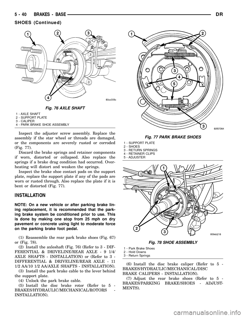
Inspect the adjuster screw assembly. Replace the
assembly if the star wheel or threads are damaged,
or the components are severely rusted or corroded
(Fig. 77).
Discard the brake springs and retainer components
if worn, distorted or collapsed. Also replace the
springs if a brake drag condition had occurred. Over-
heating will distort and weaken the springs.
Inspect the brake shoe contact pads on the support
plate, replace the support plate if any of the pads are
worn or rusted through. Also replace the plate if it is
bent or distorted (Fig. 77).
INSTALLATION
NOTE: On a new vehicle or after parking brake lin-
ing replacement, it is recommended that the park-
ing brake system be conditioned prior to use. This
is done by making one stop from 25 mph on dry
pavement or concrete using light to moderate force
on the parking brake foot pedal.
(1) Reassemble the rear park brake shoes (Fig. 67)
or (Fig. 78).
(2) Install the axleshaft (Fig. 76) (Refer to 3 - DIF-
FERENTIAL & DRIVELINE/REAR AXLE - 9 1/4/
AXLE SHAFTS - INSTALLATION) or (Refer to 3 -
DIFFERENTIAL & DRIVELINE/REAR AXLE - 11
1/2 AA/10 1/2 AA/AXLE SHAFTS - INSTALLATION).
(3) Install the park brake cable to the lever behind
the support plate.
(4) Unlock the park brake cable.
(5) Install the disc brake rotor (Refer to 5 -
BRAKES/HYDRAULIC/MECHANICAL/ROTORS -
INSTALLATION).(6) Install the disc brake caliper (Refer to 5 -
BRAKES/HYDRAULIC/MECHANICAL/DISC
BRAKE CALIPERS - INSTALLATION).
(7) Adjust the rear brake shoes (Refer to 5 -
BRAKES/PARKING BRAKE/SHOES - ADJUST-
MENTS).
Fig. 76 AXLE SHAFT
1 - AXLE SHAFT
2 - SUPPORT PLATE
3 - CALIPER
4 - PARK BRAKE SHOE ASSEMBLY
Fig. 77 PARK BRAKE SHOES
1 - SUPPORT PLATE
2 - SHOES
3 - RETURN SPRINGS
4 - RETAINER CLIPS
5 - ADJUSTER
Fig. 78 SHOE ASSEMBLY
1 - Park Brake Shoes
2 - Hold Downs
3 - Return Springs
5 - 40 BRAKES - BASEDR
SHOES (Continued)