1998 DODGE RAM 1500 clock
[x] Cancel search: clockPage 1482 of 2627
INSTALLATION
(1) Install new valve seals. The yellow seals are for
the intake valves and the green seals are for the
exhaust valves.
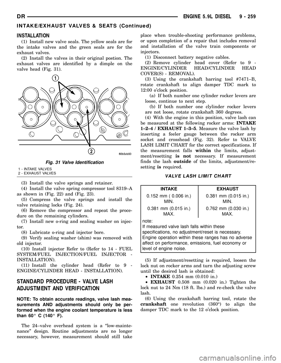
(2) Install the valves in their original postion. The
exhaust valves are identified by a dimple on the
valve head (Fig. 31).
(3) Install the valve springs and retainer.
(4) Install the valve spring compressor tool 8319±A
as shown in (Fig. 22) and (Fig. 23).
(5) Compress the valve springs and install the
valve retaining locks (Fig. 24).
(6) Remove the compressor and repeat the proce-
dure on the remaining cylinders.
(7) Install new o-ring and sealing washer on injec-
tor.
(8) Lubricate o-ring and injector bore.
(9) Verify sealing washer (shim) was removed with
old injector.
(10) Install injector Refer to (Refer to 14 - FUEL
SYSTEM/FUEL INJECTION/FUEL INJECTOR -
INSTALLATION).
(11) Install the cylinder head (Refer to 9 -
ENGINE/CYLINDER HEAD - INSTALLATION).
STANDARD PROCEDURE - VALVE LASH
ADJUSTMENT AND VERIFICATION
NOTE: To obtain accurate readings, valve lash mea-
surements AND adjustments should only be per-
formed when the engine coolant temperature is less
than 60É C (140É F).
The 24±valve overhead system is a ªlow-mainte-
nanceº design. Routine adjustments are no longer
necessary, however, measurement should still takeplace when trouble-shooting performance problems,
or upon completion of a repair that includes removal
and installation of the valve train components or
injectors.
(1) Disconnect battery negative cables.
(2) Remove cylinder head cover (Refer to 9 -
ENGINE/CYLINDER HEAD/CYLINDER HEAD
COVER(S) - REMOVAL).
(3) Using the crankshaft barring tool #7471±B,
rotate crankshaft to align damper TDC mark to
12:00 o'clock position.
(a) If both number one cylinder rocker levers are
loose, continue to next step.
(b) If both number one clylinder rocker levers
are not loose, rotate crankshaft 360 degrees.
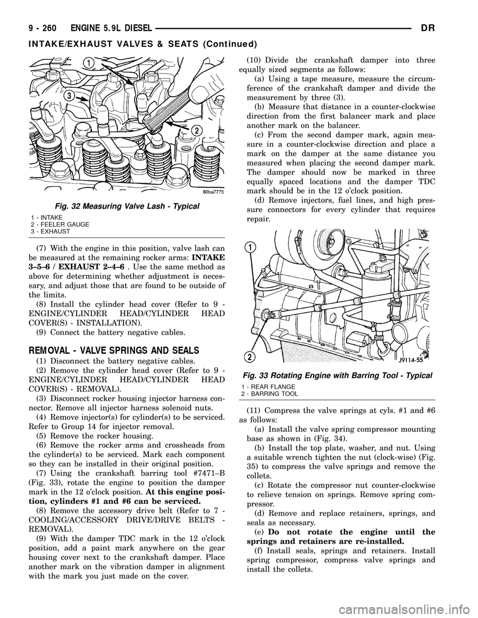
(4) With the engine in this position, valve lash can
be measured at the following rocker arms:INTAKE
1±2±4 / EXHAUST 1±3±5. Measure the valve lash by
inserting a feeler gauge between the rocker arm
socket and crosshead (Fig. 32). Refer to VALVE
LASH LIMIT CHART for the correct specifications. If
the measurement fallswithinthe limits, adjust-
ment/resettingis notnecessary. If measurement
finds the lashoutsideof the limits, adjustment/re-
settingisrequired.
VALVE LASH LIMIT CHART
INTAKE EXHAUST
0.152 mm ( 0.006 in.)
MIN.0.381 mm (0.015 in.)
MIN.
0.381 mm (0.015 in.)
MAX.0.762 mm (0.030 in.)
MAX.
note:
If measured valve lash falls within these
specifications, no adjustment/reset is necessary.
Engine operation within these ranges has no adverse
affect on performance, emissions, fuel economy or
level of engine noise.
(5) If adjustment/resetting is required, loosen the
lock nut on rocker arms and turn the adjusting screw
until the desired lash is obtained:
²INTAKE0.254 mm (0.010 in.)
²EXHAUST0.508 mm (0.020 in.) Tighten the
lock nut to 24 Nm (18 ft. lbs.) and re-check the valve
lash.
(6) Using the crankshaft barring tool, rotate the
crankshaftone revolution (360É) to align the
damper TDC mark to the 12 o'clock position.
Fig. 31 Valve Identification
1 - INTAKE VALVES
2 - EXHAUST VALVES
DRENGINE 5.9L DIESEL 9 - 259
INTAKE/EXHAUST VALVES & SEATS (Continued)
Page 1483 of 2627
(7) With the engine in this position, valve lash can
be measured at the remaining rocker arms:INTAKE
3±5±6 / EXHAUST 2±4±6. Use the same method as
above for determining whether adjustment is neces-
sary, and adjust those that are found to be outside of
the limits.
(8) Install the cylinder head cover (Refer to 9 -
ENGINE/CYLINDER HEAD/CYLINDER HEAD
COVER(S) - INSTALLATION).
(9) Connect the battery negative cables.
REMOVAL - VALVE SPRINGS AND SEALS
(1) Disconnect the battery negative cables.
(2) Remove the cylinder head cover (Refer to 9 -
ENGINE/CYLINDER HEAD/CYLINDER HEAD
COVER(S) - REMOVAL).
(3) Disconnect rocker housing injector harness con-
nector. Remove all injector harness solenoid nuts.
(4) Remove injector(s) for cylinder(s) to be serviced.
Refer to Group 14 for injector removal.
(5) Remove the rocker housing.
(6) Remove the rocker arms and crossheads from
the cylinder(s) to be serviced. Mark each component
so they can be installed in their original position.
(7) Using the crankshaft barring tool #7471±B
(Fig. 33), rotate the engine to position the damper
mark in the 12 o'clock position.At this engine posi-
tion, cylinders #1 and #6 can be serviced.
(8) Remove the accessory drive belt (Refer to 7 -
COOLING/ACCESSORY DRIVE/DRIVE BELTS -
REMOVAL).
(9) With the damper TDC mark in the 12 o'clock
position, add a paint mark anywhere on the gear
housing cover next to the crankshaft damper. Place
another mark on the vibration damper in alignment
with the mark you just made on the cover.(10) Divide the crankshaft damper into three
equally sized segments as follows:
(a) Using a tape measure, measure the circum-
ference of the crankshaft damper and divide the
measurement by three (3).
(b) Measure that distance in a counter-clockwise
direction from the first balancer mark and place
another mark on the balancer.
(c) From the second damper mark, again mea-
sure in a counter-clockwise direction and place a
mark on the damper at the same distance you
measured when placing the second damper mark.
The damper should now be marked in three
equally spaced locations and the damper TDC
mark should be in the 12 o'clock position.
(d) Remove injectors, fuel lines, and high pres-
sure connectors for every cylinder that requires
repair.
(11) Compress the valve springs at cyls. #1 and #6
as follows:
(a) Install the valve spring compressor mounting
base as shown in (Fig. 34).
(b) Install the top plate, washer, and nut. Using
a suitable wrench tighten the nut (clock-wise) (Fig.
35) to compress the valve springs and remove the
collets.
(c) Rotate the compressor nut counter-clockwise
to relieve tension on springs. Remove spring com-
pressor.
(d) Remove and replace retainers, springs, and
seals as necessary.
(e)Do not rotate the engine until the
springs and retainers are re-installed.
(f) Install seals, springs and retainers. Install
spring compressor, compress valve springs and
install the collets.
Fig. 32 Measuring Valve Lash - Typical
1 - INTAKE
2 - FEELER GAUGE
3 - EXHAUST
Fig. 33 Rotating Engine with Barring Tool - Typical
1 - REAR FLANGE
2 - BARRING TOOL
9 - 260 ENGINE 5.9L DIESELDR
INTAKE/EXHAUST VALVES & SEATS (Continued)
Page 1499 of 2627
(6) Apply a bead of MopartSilicone Rubber Adhe-
sive Sealant or equivalent to the gear housing cover
sealing surface.
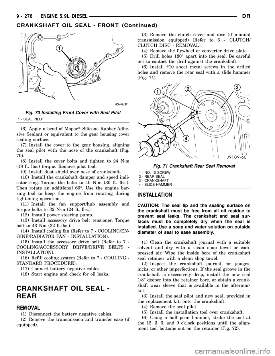
(7) Install the cover to the gear housing, aligning
the seal pilot with the nose of the crankshaft (Fig.
70).
(8) Install the cover bolts and tighten to 24 N´m
(18 ft. lbs.) torque. Remove pilot tool.
(9) Install dust shield over nose of crankshaft.
(10) Install the crankshaft damper and speed indi-
cator ring. Torque the bolts to 40 N´m (30 ft. lbs.).
Then rotate an additional 60É. Use the engine bar-
ring tool to keep the engine from rotating during
tightening operation.
(11) Install the fan support/hub assembly and
torque bolts to 32 N´m (24 ft. lbs.).
(12) Install power steering pump.
(13) Install accessory drive belt tensioner. Torque
bolt to 43 Nm (32 ft.lbs.).
(14) Install cooling fan (Refer to 7 - COOLING/EN-
GINE/RADIATOR FAN - INSTALLATION).
(15) Install the accessory drive belt (Refer to 7 -
COOLING/ACCESSORY DRIVE/DRIVE BELTS -
INSTALLATION).
(16) Refill cooling system (Refer to 7 - COOLING -
STANDARD PROCEDURE).
(17) Connect battery negative cables.
(18) Start engine and check for oil leaks.
CRANKSHAFT OIL SEAL -
REAR
REMOVAL
(1) Disconnect the battery negative cables.
(2) Remove the transmission and transfer case (if
equipped).(3) Remove the clutch cover and disc (if manual
transmission equipped) (Refer to 6 - CLUTCH/
CLUTCH DISC - REMOVAL).
(4) Remove the flywheel or converter drive plate.
(5) Drill holes 180É apart into the seal. Be careful
not to contact the drill against the crankshaft.
(6) Install #10 sheet metal screws in the drilled
holes and remove the rear seal with a slide hammer
(Fig. 71).
INSTALLATION
CAUTION: The seal lip and the sealing surface on
the crankshaft must be free from all oil residue to
prevent seal leaks. The crankshaft and seal sur-
faces must be completely dry when the seal is
installed. Use a soap and water solution on outside
diameter of seal to ease assembly.
(1) Clean the crankshaft journal with a suitable
solvent and dry with a clean shop towel or com-
pressed air. Wipe the inside bore of the crankshaft
seal retainer with a clean shop towel.
(2) Inspect the crankshaft journal for gouges,
nicks, or other imperfections. If the seal groove in the
crankshaft is excessively deep, install the new seal
1/8º deeper into the retainer bore, or obtain a crank-
shaft wear sleeve that is available in the aftermar-
ket.
(3) Install the seal pilot and new seal, provided in
the replacement kit, onto the crankshaft.
(4) Remove the seal pilot.
(5) Install the installation tool over crankshaft.
(6) Using a ball peen hammer, strike the tool at
the 12, 3, 6, and 9 o'clock positions until the align-
ment tool bottoms out on the retainer (Fig. 72).
Fig. 70 Installing Front Cover with Seal Pilot
1 - SEAL PILOT
Fig. 71 Crankshaft Rear Seal Removal
1 - NO. 10 SCREW
2 - REAR SEAL
3 - CRANKSHAFT
4 - SLIDE HAMMER
9 - 276 ENGINE 5.9L DIESELDR
CRANKSHAFT OIL SEAL - FRONT (Continued)
Page 1501 of 2627
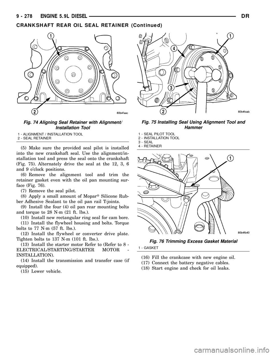
(5) Make sure the provided seal pilot is installed
into the new crankshaft seal. Use the alignment/in-
stallation tool and press the seal onto the crankshaft
(Fig. 75). Alternately drive the seal at the 12, 3, 6
and 9 o'clock positions.
(6) Remove the alignment tool and trim the
retainer gasket even with the oil pan mounting sur-
face (Fig. 76).
(7) Remove the seal pilot.
(8) Apply a small amount of MopartSilicone Rub-
ber Adhesive Sealant to the oil pan rail T-joints.
(9) Install the four (4) oil pan rear mounting bolts
and torque to 28 N´m (21 ft. lbs.).
(10) Install new rectangular ring seal for cam bore.
(11) Install the flywheel housing and bolts. Torque
bolts to 77 N´m (57 ft. lbs.).
(12) Install the flywheel or converter drive plate.
Tighten bolts to 137 N´m (101 ft. lbs.).
(13) Install the starter motor Refer to (Refer to 8 -
ELECTRICAL/STARTING/STARTER MOTOR -
INSTALLATION).
(14) Install the transmission and transfer case (if
equipped).
(15) Lower vehicle.(16) Fill the crankcase with new engine oil.
(17) Connect the battery negative cables.
(18) Start engine and check for oil leaks.
Fig. 74 Aligning Seal Retainer with Alignment/
Installation Tool
1 - ALIGNMENT / INSTALLATION TOOL
2 - SEAL RETAINER
Fig. 75 Installing Seal Using Alignment Tool and
Hammer
1 - SEAL PILOT TOOL
2 - INSTALLATION TOOL
3 - SEAL
4 - RETAINER
Fig. 76 Trimming Excess Gasket Material
1 - GASKET
9 - 278 ENGINE 5.9L DIESELDR
CRANKSHAFT REAR OIL SEAL RETAINER (Continued)
Page 1507 of 2627
(10)For fractured/split type connecting rods,
the long end of the rod must be installed towards the
intake side of the engine.
(a) The connecting rod split/face must face
toward the same side as the piston notch feature
on the skirt. The split face will face toward the
exhaust side of the engine if properly installed.
(11) Install the rod cap and bolts to the connecting
rod. Tighten the connecting rod bolts evenly in 3
steps.
²Tighten the bolts to 30 N´m (22 ft. lbs.) torque.
²Tighten the bolts to 60 N´m (44 ft. lbs.) torque.
²Rotate 60É clockwise.
(12) The crankshaft must rotate freely. Check for
freedom of rotation as the caps are installed. If the
crankshaft does not rotate freely, check the installa-
tion of the rod bearing and the bearing size.
(13) Measure the side clearance between the con-
necting rod and the crankshaft. DO NOT measure
the clearance between the cap and crankshaft.
(14) Install J-jet piston cooling nozzles if equipped.
(15) Install block stiffener. Torque to 43 N´m (32 ft.
lbs.).
(16) Install the suction tube and oil pan (Refer to 9
- ENGINE/LUBRICATION/OIL PAN - INSTALLA-
TION).
(17) Install the cylinder head onto the engine
(Refer to 9 - ENGINE/CYLINDER HEAD - INSTAL-
LATION).
(18) Install a new filter and fill the crankcase with
new engine oil.Prefill the filter with clean oil.
(19) Connect the battery negative cables and start
engine.
PISTON RINGS
STANDARD PROCEDURE - PISTON RING
FITTING
(1) Determine the piston diameter and obtain the
appropriate ring set. The piston rings can be identi-
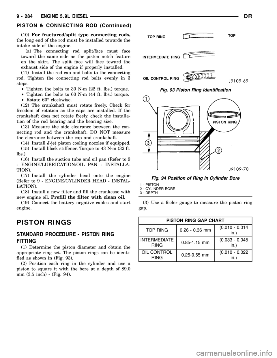
fied as shown in (Fig. 93).
(2) Position each ring in the cylinder and use a
piston to square it with the bore at a depth of 89.0
mm (3.5 inch) - (Fig. 94).(3) Use a feeler gauge to measure the piston ring
gap.
PISTON RING GAP CHART
TOP RING 0.26 - 0.36 mm(0.010 - 0.014
in.)
INTERMEDIATE
RING0.85-1.15 mm(0.033 - 0.045
in.)
OIL CONTROL
RING0.25-0.55 mm(0.010 - 0.022
in.)
Fig. 93 Piston Ring Identification
Fig. 94 Position of Ring in Cylinder Bore
1 - PISTON
2 - CYLINDER BORE
3 - DEPTH
9 - 284 ENGINE 5.9L DIESELDR
PISTON & CONNECTING ROD (Continued)
Page 1517 of 2627
OIL PRESSURE RELIEF VALVE
REMOVAL
(1) Disconnect the battery negative cables.
(2) Remove the threaded plug, spring and plunger
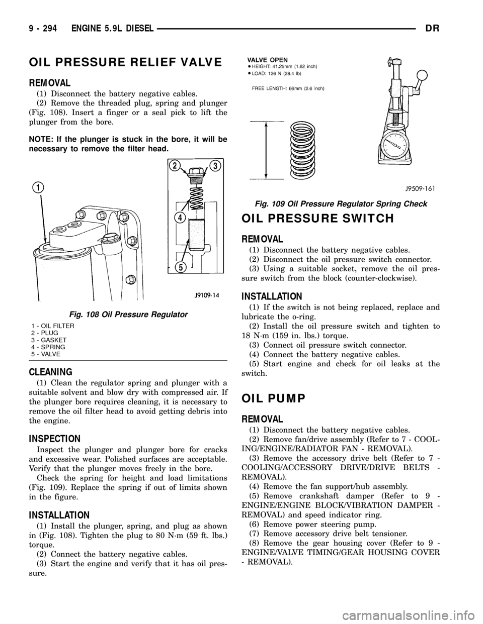
(Fig. 108). Insert a finger or a seal pick to lift the
plunger from the bore.
NOTE: If the plunger is stuck in the bore, it will be
necessary to remove the filter head.
CLEANING
(1) Clean the regulator spring and plunger with a
suitable solvent and blow dry with compressed air. If
the plunger bore requires cleaning, it is necessary to
remove the oil filter head to avoid getting debris into
the engine.
INSPECTION
Inspect the plunger and plunger bore for cracks
and excessive wear. Polished surfaces are acceptable.
Verify that the plunger moves freely in the bore.
Check the spring for height and load limitations
(Fig. 109). Replace the spring if out of limits shown
in the figure.
INSTALLATION
(1) Install the plunger, spring, and plug as shown
in (Fig. 108). Tighten the plug to 80 N´m (59 ft. lbs.)
torque.
(2) Connect the battery negative cables.
(3) Start the engine and verify that it has oil pres-
sure.
OIL PRESSURE SWITCH
REMOVAL
(1) Disconnect the battery negative cables.
(2) Disconnect the oil pressure switch connector.
(3) Using a suitable socket, remove the oil pres-
sure switch from the block (counter-clockwise).
INSTALLATION
(1) If the switch is not being replaced, replace and
lubricate the o-ring.
(2) Install the oil pressure switch and tighten to
18 N´m (159 in. lbs.) torque.
(3) Connect oil pressure switch connector.
(4) Connect the battery negative cables.
(5) Start engine and check for oil leaks at the
switch.
OIL PUMP
REMOVAL
(1) Disconnect the battery negative cables.
(2) Remove fan/drive assembly (Refer to 7 - COOL-
ING/ENGINE/RADIATOR FAN - REMOVAL).
(3) Remove the accessory drive belt (Refer to 7 -
COOLING/ACCESSORY DRIVE/DRIVE BELTS -
REMOVAL).
(4) Remove the fan support/hub assembly.
(5) Remove crankshaft damper (Refer to 9 -
ENGINE/ENGINE BLOCK/VIBRATION DAMPER -
REMOVAL) and speed indicator ring.
(6) Remove power steering pump.
(7) Remove accessory drive belt tensioner.
(8) Remove the gear housing cover (Refer to 9 -
ENGINE/VALVE TIMING/GEAR HOUSING COVER
- REMOVAL).
Fig. 108 Oil Pressure Regulator
1 - OIL FILTER
2 - PLUG
3 - GASKET
4 - SPRING
5 - VALVE
Fig. 109 Oil Pressure Regulator Spring Check
9 - 294 ENGINE 5.9L DIESELDR
Page 1522 of 2627
(3) Install heat shield and torque nuts to 15 Nm
(11 ft. lbs.).
(4) Install cab heater tube.
(5) Install exhaust manifold bolt retention straps.
(6) Install the cab heater return hose to the man-
ifold bolt stud. Tighten the nut to 24 N´m (18 ft. lbs.)
torque.
(7) Install the turbocharger and a new gasket.
Apply anti-seize to the studs and then tighten the
turbocharger mounting nuts to 43 N´m (32 ft. lbs.)
torque.
(8)Pre-lube the turbocharger.Pour 50 to 60 cc
(2 to 3 oz.) clean engine oil in the oil supply line fit-
ting on the turbo. Rotate the turbocharger impeller
by hand to distrubute the oil thoroughly.
(9) Install and tighten the oil supply line fitting
nut to 24 N´m (18 ft. lbs.) torque.
(10) Position the charge air cooler inlet pipe to the
turbocharger. With the clamp in position, tighten the
clamp nut to 11 N´m (100 in. lbs.) torque.
(11) Position the air inlet hose to the turbocharger.
Tighten the clamp to 11 N´m (100 in. lbs.) torque.
(12) Raise vehicle on hoist.
(13) Install the oil drain tube and a new gasket to
the turbocharger. Tighten the drain tube bolts to 24
N´m (18 ft. lbs.) torque.
(14) Connect the exhaust pipe to the turbocharger
and tighten the bolts to 11 N´m (100 ft. lbs.) torque.
(15) Lower the vehicle.
(16) Connect the battery negative cables.
(17) Start the engine to check for leaks.
VALVE TIMING
STANDARD PROCEDURE - TIMING
VERIFICATION
(1) Remove the cylinder head cover(Refer to 9 -
ENGINE/CYLINDER HEAD/CYLINDER HEAD
COVER(S) - REMOVAL).
(2) Remove fuel injector from cylinder number
1(Refer to 14 - FUEL SYSTEM/FUEL INJECTION/
FUEL INJECTOR - REMOVAL).
(3) Using Special Tool 7471B rotate the engine
until the TDC mark on the damper is at 12 o'clock.
(4) Using a 8 in.x 1/4 in. dowel rod inserted into
cylinder number 1, rock the crankshaft back and
forth to verify piston number 1 is at TDC.
(5) With cylinder number still at TDC, inspect the
keyway on the crankshaft gear for proper alignment
(12 o'clock position).
(6) If the keyway is not at 12 o'clock position
replace the crankshaft gear assembly.
(7) If the keyway is at 12 o'clock position, remove
front gear cover and verify timing mark alignmentbetween the camshaft gear and crankshaft gear, if
not aligned inspect keyway on camshaft gear.
(8) Inspect keyway on camshaft gear for proper
alignment with the key in the camshaft, if alignment
is off replace the camshaft/gear assembly.
(9) If timing marks alignment is off and no dam-
age is found at either the crankshaft or camshaft
gear keyways, realign timing marks as necessary.
GEAR HOUSING
REMOVAL
(1) Disconnect the battery negative cables.
(2) Raise vehicle on hoist.
(3) Partially drain engine coolant into container
suitable for re-use (Refer to 7 - COOLING - STAN-
DARD PROCEDURE).
(4) Lower vehicle.
(5) Remove radiator upper hose.
(6) Disconnect coolant recovery bottle hose from
radiator filler neck and lift bottle off of fan shroud.
(7) Disconnect windshield washer pump supply
hose and electrical connections and lift washer bottle
off of fan shroud.
(8) Remove lower fan shroud fasteners. Disconnect
fan drive wire harness.
(9) Remove the upper fan shroud-to-radiator
mounting bolts.
(10) Remove viscous fan/drive assembly (Refer to 7
- COOLING/ENGINE/RADIATOR FAN - REMOVAL).
(11) Remove the accessory drive belt (Refer to 7 -
COOLING/ACCESSORY DRIVE/DRIVE BELTS -
REMOVAL).
(12) Remove the cooling fan support/hub from the
front of the engine.
(13) Raise the vehicle on hoist.
(14) Remove the crankshaft damper (Refer to 9 -
ENGINE/ENGINE BLOCK/VIBRATION DAMPER -
REMOVAL) and speed indicator ring.
(15) Lower the vehicle.
(16) Remove the power steering pump.
(17) Remove the accessory drive belt tensioner.
(18) Remove the gear cover-to-housing bolts and
gently pry the cover away from the housing, taking
care not to mar the gasket surfaces.
(19) Remove the fuel injection pump (Refer to 14 -
FUEL SYSTEM/FUEL DELIVERY/FUEL INJEC-
TION PUMP - REMOVAL).
(20) Disconnect the camshaft position sensor con-
nector.
(21) Disconnect and remove engine speed sensor.
(22) Remove the camshaft (Refer to 9 - ENGINE/
ENGINE BLOCK/CAMSHAFT & BEARINGS (IN
BLOCK) - REMOVAL).
(23) Remove the six front oil pan fasteners.
DRENGINE 5.9L DIESEL 9 - 299
EXHAUST MANIFOLD (Continued)
Page 1599 of 2627
INTAKE AIR TEMPERATURE
SENSOR
DESCRIPTION
The 2±wire Intake Manifold Air Temperature (IAT)
sensor is installed in the intake manifold with the
sensor element extending into the air stream.
The IAT sensor is a two-wire Negative Thermal
Coefficient (NTC) sensor. Meaning, as intake mani-
fold temperature increases, resistance (voltage) in the
sensor decreases. As temperature decreases, resis-
tance (voltage) in the sensor increases.
OPERATION
The IAT sensor provides an input voltage to the
Powertrain Control Module (PCM) indicating the
density of the air entering the intake manifold based
upon intake manifold temperature. At key-on, a
5±volt power circuit is supplied to the sensor from
the PCM. The sensor is grounded at the PCM
through a low-noise, sensor-return circuit.
The PCM uses this input to calculate the following:²Injector pulse-width
²Adjustment of spark timing (to help prevent
spark knock with high intake manifold air-charge
temperatures)
The resistance values of the IAT sensor is the same
as for the Engine Coolant Temperature (ECT) sensor.
REMOVAL
3.7L V-6
The intake manifold air temperature (IAT) sensor
is installed into the left side of intake manifold ple-
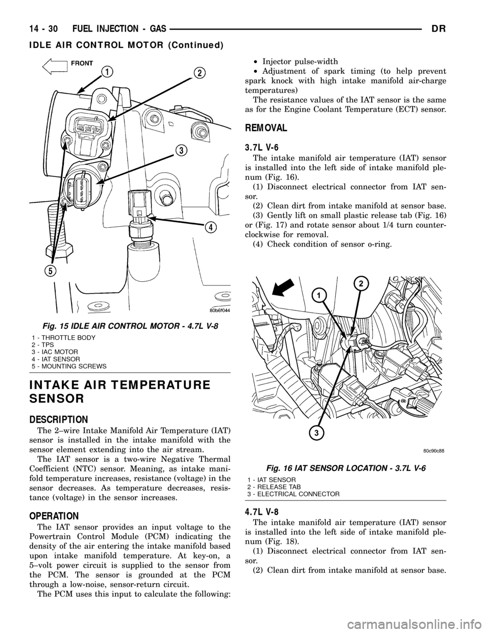
num (Fig. 16).
(1) Disconnect electrical connector from IAT sen-
sor.
(2) Clean dirt from intake manifold at sensor base.
(3) Gently lift on small plastic release tab (Fig. 16)
or (Fig. 17) and rotate sensor about 1/4 turn counter-
clockwise for removal.
(4) Check condition of sensor o-ring.
4.7L V-8
The intake manifold air temperature (IAT) sensor
is installed into the left side of intake manifold ple-
num (Fig. 18).
(1) Disconnect electrical connector from IAT sen-
sor.
(2) Clean dirt from intake manifold at sensor base.
Fig. 15 IDLE AIR CONTROL MOTOR - 4.7L V-8
1 - THROTTLE BODY
2 - TPS
3 - IAC MOTOR
4 - IAT SENSOR
5 - MOUNTING SCREWS
Fig. 16 IAT SENSOR LOCATION - 3.7L V-6
1 - IAT SENSOR
2 - RELEASE TAB
3 - ELECTRICAL CONNECTOR
14 - 30 FUEL INJECTION - GASDR
IDLE AIR CONTROL MOTOR (Continued)