1998 DODGE RAM 1500 clock
[x] Cancel search: clockPage 1249 of 2627
(2) Set engine to TDC cylinder #1, camshaft
sprocket V6 marks at the 12 o'clock position.
(3) Mark one link on the secondary timing chain
on both sides of the V6 mark on the camshaft
sprocket to aid in installation.
CAUTION: Do not hold or pry on the camshaft tar-
get wheel (Located on the right side camshaft
sprocket) for any reason, Severe damage will occur
to the target wheel resulting in a vehicle no start
condition.
(4) Loosen butDO NOTremove the camshaft
sprocket retaining bolt. Leave the bolt snug against
the sprocket.
NOTE: The timing chain tensioners must be
secured prior to removing the camshaft sprockets.
Failure to secure tensioners will allow the tension-
ers to extend, requiring timing chain cover removal
in order to reset tensioners.
CAUTION: Do not force wedge past the narrowest
point between the chain strands. Damage to the
tensioners may occur.
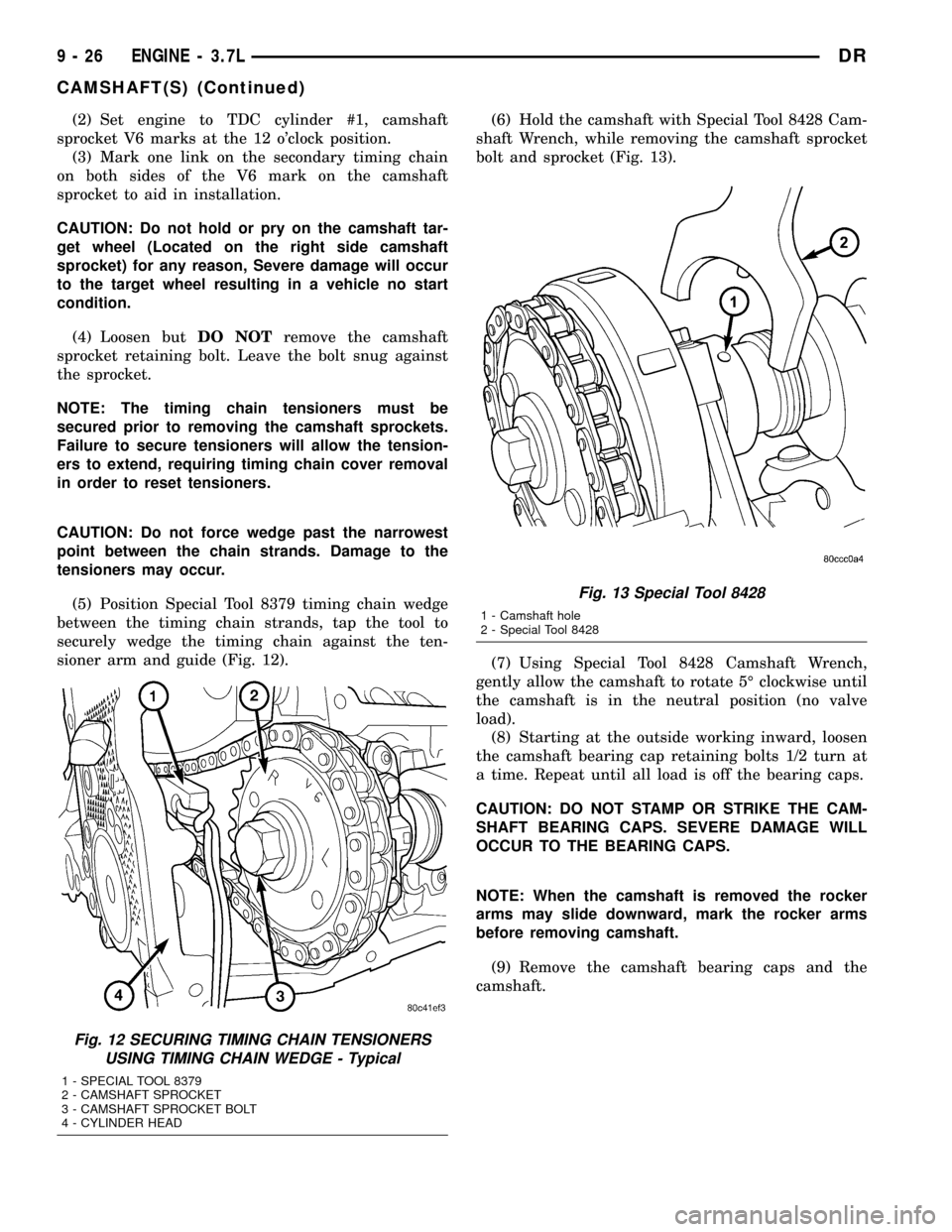
(5) Position Special Tool 8379 timing chain wedge
between the timing chain strands, tap the tool to
securely wedge the timing chain against the ten-
sioner arm and guide (Fig. 12).(6) Hold the camshaft with Special Tool 8428 Cam-
shaft Wrench, while removing the camshaft sprocket
bolt and sprocket (Fig. 13).
(7) Using Special Tool 8428 Camshaft Wrench,
gently allow the camshaft to rotate 5É clockwise until
the camshaft is in the neutral position (no valve
load).
(8) Starting at the outside working inward, loosen
the camshaft bearing cap retaining bolts 1/2 turn at
a time. Repeat until all load is off the bearing caps.
CAUTION: DO NOT STAMP OR STRIKE THE CAM-
SHAFT BEARING CAPS. SEVERE DAMAGE WILL
OCCUR TO THE BEARING CAPS.
NOTE: When the camshaft is removed the rocker
arms may slide downward, mark the rocker arms
before removing camshaft.
(9) Remove the camshaft bearing caps and the
camshaft.
Fig. 12 SECURING TIMING CHAIN TENSIONERS
USING TIMING CHAIN WEDGE - Typical
1 - SPECIAL TOOL 8379
2 - CAMSHAFT SPROCKET
3 - CAMSHAFT SPROCKET BOLT
4 - CYLINDER HEAD
Fig. 13 Special Tool 8428
1 - Camshaft hole
2 - Special Tool 8428
9 - 26 ENGINE - 3.7LDR
CAMSHAFT(S) (Continued)
Page 1250 of 2627
INSTALLATION
(1) Lubricate camshaft journals with clean engine
oil.
NOTE: Position the left side camshaft so that the
camshaft sprocket dowel is near the 1 o'clock posi-
tion, This will place the camshaft at the neutral
position easing the installation of the camshaft
bearing caps.
(2) Position the camshaft into the cylinder head.
(3) Install the camshaft bearing caps, hand tighten
the retaining bolts.
NOTE: Caps should be installed so that the
stamped numbers on the caps are in numerical
order, ( 1 thru 4 ) from the front to the rear of the
engine. All caps should be installed so that the
stamped arrows on the caps point toward the front
of the engine.
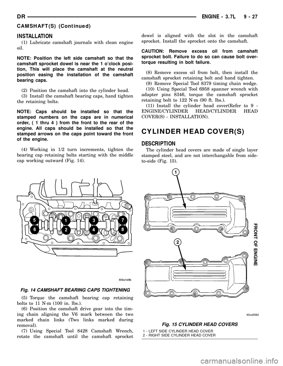
(4) Working in 1/2 turn increments, tighten the
bearing cap retaining bolts starting with the middle
cap working outward (Fig. 14).
(5) Torque the camshaft bearing cap retaining
bolts to 11 N´m (100 in. lbs.).
(6) Position the camshaft drive gear into the tim-
ing chain aligning the V6 mark between the two
marked chain links (Two links marked during
removal).
(7) Using Special Tool 8428 Camshaft Wrench,
rotate the camshaft until the camshaft sprocketdowel is aligned with the slot in the camshaft
sprocket. Install the sprocket onto the camshaft.
CAUTION: Remove excess oil from camshaft
sprocket bolt. Failure to do so can cause bolt over-
torque resulting in bolt failure.
(8) Remove excess oil from bolt, then install the
camshaft sprocket retaining bolt and hand tighten.
(9) Remove Special Tool 8379 timing chain wedge.
(10) Using Special Tool 6958 spanner wrench with
adapter pins 8346, torque the camshaft sprocket
retaining bolt to 122 N´m (90 ft. lbs.).
(11) Install the cylinder head cover(Refer to 9 -
ENGINE/CYLINDER HEAD/CYLINDER HEAD
COVER(S) - INSTALLATION).
CYLINDER HEAD COVER(S)
DESCRIPTION
The cylinder head covers are made of single layer
stamped steel, and are not interchangable from side-
to-side (Fig. 15).
Fig. 14 CAMSHAFT BEARING CAPS TIGHTENING
Fig. 15 CYLINDER HEAD COVERS
1 - LEFT SIDE CYLINDER HEAD COVER
2 - RIGHT SIDE CYLINDER HEAD COVER
DRENGINE - 3.7L 9 - 27
CAMSHAFT(S) (Continued)
Page 1253 of 2627
TESTING VALVE SPRINGS
NOTE: Whenever the valves are removed from the
cylinder head it is recommended that the valve
springs be inspected and tested for reuse.
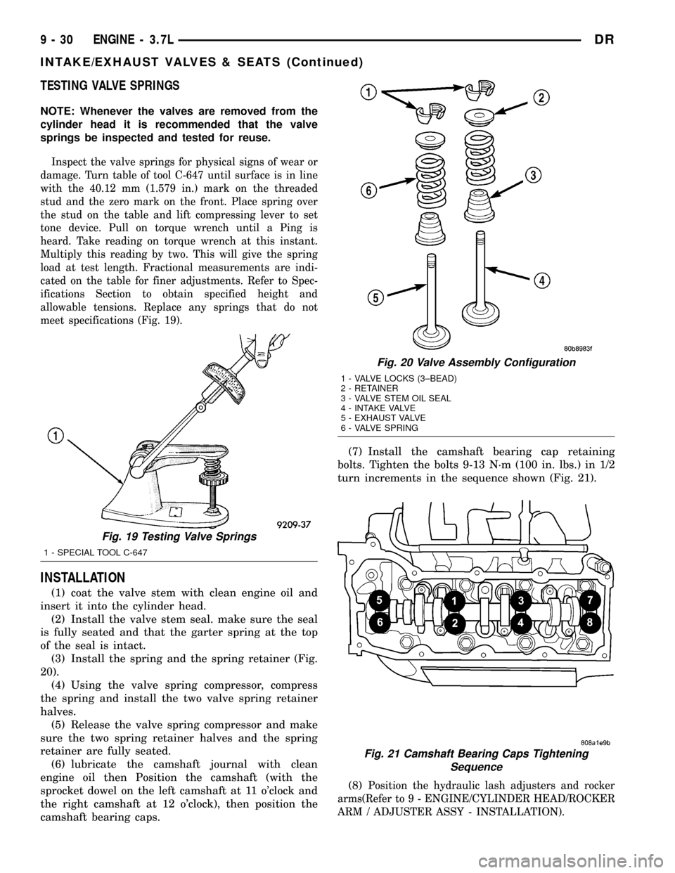
Inspect the valve springs for physical signs of wear or
damage. Turn table of tool C-647 until surface is in line
with the 40.12 mm (1.579 in.) mark on the threaded
stud and the zero mark on the front. Place spring over
the stud on the table and lift compressing lever to set
tone device. Pull on torque wrench until a Ping is
heard. Take reading on torque wrench at this instant.
Multiply this reading by two. This will give the spring
load at test length. Fractional measurements are indi-
cated on the table for finer adjustments. Refer to Spec-
ifications Section to obtain specified height and
allowable tensions. Replace any springs that do not
meet specifications (Fig. 19).
INSTALLATION
(1) coat the valve stem with clean engine oil and
insert it into the cylinder head.
(2) Install the valve stem seal. make sure the seal
is fully seated and that the garter spring at the top
of the seal is intact.
(3) Install the spring and the spring retainer (Fig.
20).
(4) Using the valve spring compressor, compress
the spring and install the two valve spring retainer
halves.
(5) Release the valve spring compressor and make
sure the two spring retainer halves and the spring
retainer are fully seated.
(6) lubricate the camshaft journal with clean
engine oil then Position the camshaft (with the
sprocket dowel on the left camshaft at 11 o'clock and
the right camshaft at 12 o'clock), then position the
camshaft bearing caps.(7) Install the camshaft bearing cap retaining
bolts. Tighten the bolts 9-13 N´m (100 in. lbs.) in 1/2
turn increments in the sequence shown (Fig. 21).
(8)
Position the hydraulic lash adjusters and rocker
arms(Refer to 9 - ENGINE/CYLINDER HEAD/ROCKER
ARM / ADJUSTER ASSY - INSTALLATION).
Fig. 19 Testing Valve Springs
1 - SPECIAL TOOL C-647
Fig. 20 Valve Assembly Configuration
1 - VALVE LOCKS (3±BEAD)
2 - RETAINER
3 - VALVE STEM OIL SEAL
4 - INTAKE VALVE
5 - EXHAUST VALVE
6 - VALVE SPRING
Fig. 21 Camshaft Bearing Caps Tightening
Sequence
9 - 30 ENGINE - 3.7LDR
INTAKE/EXHAUST VALVES & SEATS (Continued)
Page 1256 of 2627
(6) Air ingested into oil due to broken or cracked
oil pump pick up.
(7) Worn valve guides.
(8) Rocker arm ears contacting valve spring
retainer.
(9) Rocker arm loose, adjuster stuck or at maxi-
mum extension and still leaves lash in the system.
(10) Oil leak or excessive cam bore wear in cylin-
der head.
(11) Faulty lash adjuster.
a. Check lash adjusters for sponginess while
installed in cylinder head and cam on camshaft at
base circle. Depress part of rocker arm over adjuster.
Normal adjusters should feel very firm. Spongy
adjusters can be bottomed out easily.
b. Remove suspected lash adjusters, and replace.
c. Before installation, make sure adjusters are at
least partially full of oil. This can be verified by little
or no plunger travel when lash adjuster is depressed.
REMOVAL
(1) Disconnect battery negative cable.
(2) Raise the vehicle on a hoist.
(3) Disconnect the exhaust pipe at the right side
exhaust manifold.
(4) Drain the engine coolant(Refer to 7 - COOL-
ING - STANDARD PROCEDURE).
(5) Lower the vehicle.
(6) Remove the intake manifold(Refer to 9 -
ENGINE/MANIFOLDS/INTAKE MANIFOLD -
REMOVAL).
(7) Remove the cylinder head cover(Refer to 9 -
ENGINE/CYLINDER HEAD - REMOVAL).
(8) Remove the fan shroud(Refer to 7 - COOLING/
ENGINE/RADIATOR FAN - REMOVAL).
(9) Remove oil fill housing from cylinder head.
(10) Remove accessory drive belt(Refer to 7 -
COOLING/ACCESSORY DRIVE/DRIVE BELTS -
REMOVAL).
(11) Rotate the crankshaft until the damper timing
mark is aligned with TDC indicator mark.
(12) Verify the V6 mark on the camshaft sprocket
is at the 12 o'clock position. Rotate the crankshaft
one turn if necessary.
(13) Remove the crankshaft damper(Refer to 9 -
ENGINE/ENGINE BLOCK/VIBRATION DAMPER -
REMOVAL).
(14) Remove the timing chain cover(Refer to 9 -
ENGINE/VALVE TIMING/TIMING BELT / CHAIN
COVER(S) - REMOVAL).
(15) Lock the secondary timing chains to the idler
sprocket using Special Tool 8429 Timing Chain Hold-
ing Fixture.NOTE: Mark the secondary timing chain prior to
removal to aid in installation.
(16) Mark the secondary timing chain, one link on
each side of the V6 mark on the camshaft drive gear.
(17) Remove the right side secondary chain ten-
sioner(Refer to 9 - ENGINE/VALVE TIMING/TIM-
ING BELT/CHAIN AND SPROCKETS - REMOVAL).
(18) Remove the cylinder head access plug.
(19) Remove the right side secondary chain
guide(Refer to 9 - ENGINE/VALVE TIMING/TIMING
BELT/CHAIN AND SPROCKETS - REMOVAL).
CAUTION: The nut on the right side camshaft
sprocket should not be removed for any reason, as
the sprocket and camshaft sensor target wheel is
serviced as an assembly. If the nut was removed,
torque nut to 5 N´m (44 in. lbs.).
(20) Remove the retaining bolt and the camshaft
drive gear.
CAUTION: Do not allow the engine to rotate. severe
damage to the valve train can occur.
CAUTION: Do not overlook the four smaller bolts at
the front of the cylinder head. Do not attempt to
remove the cylinder head without removing these
four bolts.
CAUTION: Do not hold or pry on the camshaft tar-
get wheel for any reason. A damaged target wheel
can result in a vehicle no start condition.
NOTE: The cylinder head is attached to the cylinder
block with twelve bolts.
(21) Remove the cylinder head retaining bolts.
(22) Remove the cylinder head and gasket. Discard
the gasket.
CAUTION: Do not lay the cylinder head on its gas-
ket sealing surface, do to the design of the cylinder
head gasket any distortion to the cylinder head
sealing surface may prevent the gasket from prop-
erly sealing resulting in leaks.
DRENGINE - 3.7L 9 - 33
CYLINDER HEAD - RIGHT (Continued)
Page 1258 of 2627
CAUTION: The nut on the right side camshaft
sprocket should not be removed for any reason, as
the sprocket and camshaft sensor target wheel is
serviced as an assembly. If the nut was removed,
torque nut to 5 NM ( 60 in. lbs.).
(7) Position the secondary chain onto the camshaft
drive gear, making sure one marked chain link is on
either side of the V6 mark on the gear then using
Special Tool 8428 Camshaft Wrench, position the
gear onto the camshaft.
CAUTION: Remove excess oil from camshaft
sprocket retaining bolt before reinstalling bolt. Fail-
ure to do so may cause over-torquing of bolt result-
ing in bolt failure.
(8) Install the camshaft drive gear retaining bolt.
(9) Install the right side secondary chain guide(Re-
fer to 9 - ENGINE/VALVE TIMING/TIMING BELT/
CHAIN AND SPROCKETS - INSTALLATION).
(10) Install the cylinder head access plug.
(11) Re-set and install the right side secondary
chain tensioner(Refer to 9 - ENGINE/VALVE TIM-
ING/TIMING BELT/CHAIN AND SPROCKETS -
INSTALLATION).
(12) Remove Special Tool 8429.
(13) Install the timing chain cover(Refer to 9 -
ENGINE/VALVE TIMING/TIMING BELT / CHAIN
COVER(S) - REMOVAL).
(14) Install the crankshaft damper(Refer to 9 -
ENGINE/ENGINE BLOCK/VIBRATION DAMPER -
INSTALLATION). Tighten damper bolt 175 N´m (130
Ft. Lbs.).
(15) Install accessory drive belt(Refer to 7 - COOL-
ING/ACCESSORY DRIVE/DRIVE BELTS - INSTAL-
LATION).
(16) Install the fan shroud(Refer to 7 - COOLING/
ENGINE/RADIATOR FAN - INSTALLATION).
(17) Install the cylinder head cover(Refer to 9 -
ENGINE/CYLINDER HEAD/CYLINDER HEAD
COVER(S) - INSTALLATION).
(18) Install the intake manifold(Refer to 9 -
ENGINE/MANIFOLDS/INTAKE MANIFOLD -
INSTALLATION).
(19) Install oil fill housing onto cylinder head.
(20) Refill the cooling system(Refer to 7 - COOL-
ING - STANDARD PROCEDURE).
(21) Raise the vehicle.
(22) Install the exhaust pipe onto the right
exhaust manifold.
(23) Lower the vehicle.
(24) Reconnect battery negative cable.
(25) Start the engine and check for leaks.CAMSHAFT(S)
DESCRIPTION
The camshafts consist of powdered metal steel
lobes which are sinter-bonded to a steel tube. Four
bearing journals are machined into the camshaft.
Camshaft end play is controlled by two thrust walls
that border the nose piece journal. Engine oil enters
the hollow camshafts at the third journal and lubri-
cates every intake lobe rocker through a drilled pas-
sage in the intake lobe.
REMOVAL
CAUTION: When the timing chain is removed and
the cylinder heads are still installed, DO NOT force-
fully rotate the camshafts or crankshaft indepen-
dently of each other. Severe valve and/or piston
damage can occur.
CAUTION: When removing the cam sprocket, timing
chains or camshaft, Failure to use special tool 8379
will result in hydraulic tensioner ratchet over exten-
sion, Requiring timing chain cover removal to re-set
the tensioner ratchet.
(1) Remove the cylinder head cover(Refer to 9 -
ENGINE/CYLINDER HEAD/CYLINDER HEAD
COVER(S) - REMOVAL).
(2) Set engine to TDC cylinder No. 1, camshaft
sprocket V6 marks at the 12 o'clock position.
(3) Mark one link on the secondary timing chain
on both sides of the V6 mark on the camshaft
sprocket to aid in installation.
CAUTION: Do not hold or pry on the camshaft tar-
get wheel for any reason, Severe damage will occur
to the target wheel. A damaged target wheel could
cause a vehicle no start condition.
(4) Loosen butDO NOTremove the camshaft
sprocket retaining bolt. Leave bolt snug against
sprocket.
NOTE: The timing chain tensioners must be
secured prior to removing the camshaft sprockets.
Failure to secure tensioners will allow the tension-
ers to extend, requiring timing chain cover removal
in order to reset tensioners.
CAUTION: Do not force wedge past the narrowest
point between the chain strands. Damage to the
tensioners may occur.
DRENGINE - 3.7L 9 - 35
CYLINDER HEAD - RIGHT (Continued)
Page 1259 of 2627
(5) Position Special Tool 8379 timing chain wedge
between the timing chain strands. Tap the tool to
securely wedge the timing chain against the ten-
sioner arm and guide.
(6) Remove the camshaft position sensor.
(7) Hold the camshaft with Special Tool 8428 Cam-
shaft Wrench, while removing the camshaft sprocket
bolt and sprocket.
(8) Starting at the outside working inward, loosen
the camshaft bearing cap retaining bolts 1/2 turn at
a time. Repeat until all load is off the bearing caps.
CAUTION: DO NOT STAMP OR STRIKE THE CAM-
SHAFT BEARING CAPS. SEVERE DAMAGE WILL
OCCUR TO THE BEARING CAPS.
NOTE: When the camshaft is removed the rocker
arms may slide downward, mark the rocker arms
before removing camshaft.
(9) Remove the camshaft bearing caps and the
camshaft.
INSTALLATION
(1) Lubricate camshaft journals with clean engine
oil.
NOTE: Position the right side camshaft so that the
camshaft sprocket dowel is near the 10 o'clock
position, This will place the camshaft at the neutral
position easing the installation of the camshaft
bearing caps.
(2) Position the camshaft into the cylinder head.
(3) Install the camshaft bearing caps, hand tighten
the retaining bolts.
NOTE: Caps should be installed so that the
stamped numbers on the caps are in numerical
order, ( 1 thru 4 ) from the front to the rear of the
engine. All caps should be installed so that the
stamped arrows on the caps point toward the front
of the engine.
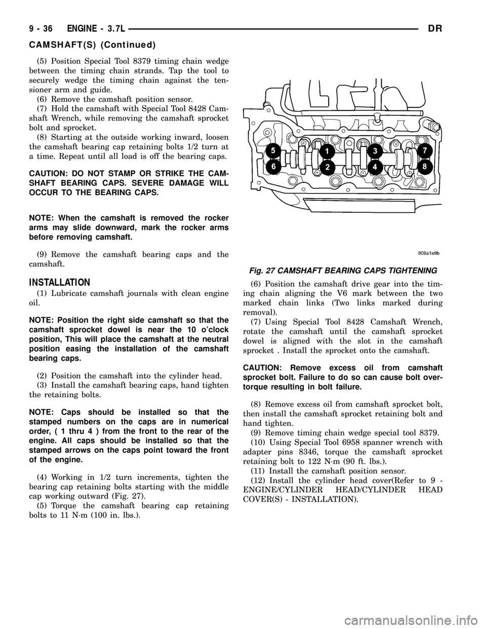
(4) Working in 1/2 turn increments, tighten the
bearing cap retaining bolts starting with the middle
cap working outward (Fig. 27).
(5) Torque the camshaft bearing cap retaining
bolts to 11 N´m (100 in. lbs.).(6) Position the camshaft drive gear into the tim-
ing chain aligning the V6 mark between the two
marked chain links (Two links marked during
removal).
(7) Using Special Tool 8428 Camshaft Wrench,
rotate the camshaft until the camshaft sprocket
dowel is aligned with the slot in the camshaft
sprocket . Install the sprocket onto the camshaft.
CAUTION: Remove excess oil from camshaft
sprocket bolt. Failure to do so can cause bolt over-
torque resulting in bolt failure.
(8) Remove excess oil from camshaft sprocket bolt,
then install the camshaft sprocket retaining bolt and
hand tighten.
(9) Remove timing chain wedge special tool 8379.
(10) Using Special Tool 6958 spanner wrench with
adapter pins 8346, torque the camshaft sprocket
retaining bolt to 122 N´m (90 ft. lbs.).
(11) Install the camshaft position sensor.
(12) Install the cylinder head cover(Refer to 9 -
ENGINE/CYLINDER HEAD/CYLINDER HEAD
COVER(S) - INSTALLATION).
Fig. 27 CAMSHAFT BEARING CAPS TIGHTENING
9 - 36 ENGINE - 3.7LDR
CAMSHAFT(S) (Continued)
Page 1293 of 2627
(5) Install the timing chain cover (Refer to 9 -
ENGINE/VALVE TIMING/TIMING BELT / CHAIN
COVER(S) - INSTALLATION).
(6) Install the pick-up tube and oil pan (Refer to 9
- ENGINE/LUBRICATION/OIL PAN - INSTALLA-
TION).
OIL FILTER
REMOVAL
All engines are equipped with a high quality full-
flow, disposable type oil filter. DaimlerChrysler Cor-
poration recommends a Mopartor equivalent oil
filter be used.
(1) Position a drain pan under the oil filter.
(2) Using a suitable oil filter wrench loosen filter.
(3) Rotate the oil filter counterclockwise (Fig. 83)
to remove it from the cylinder block oil filter boss.
(4) When filter separates from cylinder block oil
filter boss, tip gasket end upward to minimize oil
spill. Remove filter from vehicle.
NOTE: Make sure filter gasket was removed with fil-
ter.
(5) With a wiping cloth, clean the gasket sealing
surface of oil and grime.
INSTALLATION
(1) Lightly lubricate oil filter gasket with engine
oil.
(2) Thread filter onto adapter nipple. When gasket
makes contact with sealing surface, (Fig. 84) hand
tighten filter one full turn, do not over tighten.
(3) Add oil, verify crankcase oil level and start
engine. Inspect for oil leaks.
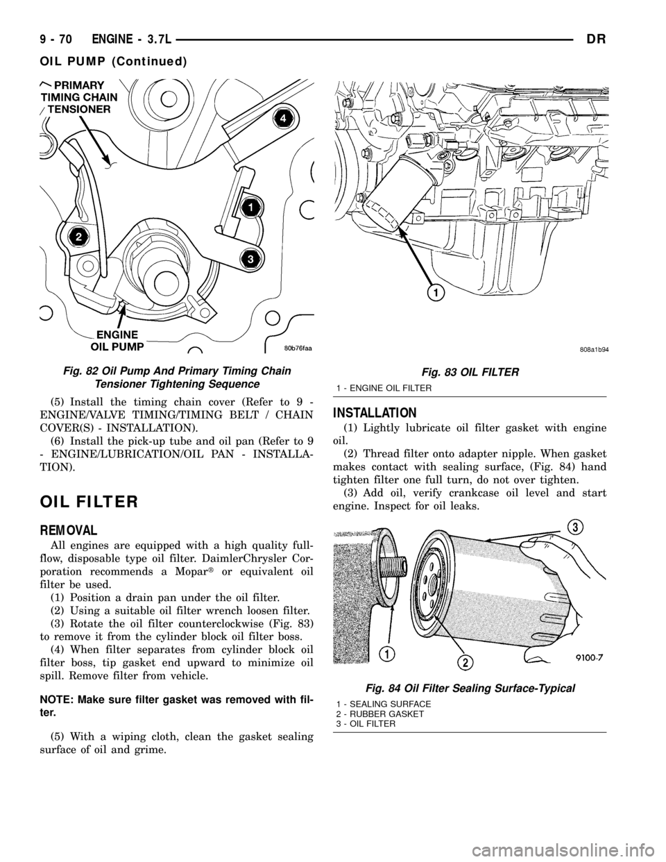
Fig. 82 Oil Pump And Primary Timing Chain
Tensioner Tightening SequenceFig. 83 OIL FILTER
1 - ENGINE OIL FILTER
Fig. 84 Oil Filter Sealing Surface-Typical
1 - SEALING SURFACE
2 - RUBBER GASKET
3 - OIL FILTER
9 - 70 ENGINE - 3.7LDR
OIL PUMP (Continued)
Page 1300 of 2627
block. A large washer on the idler shaft bolt and the
rear flange of the idler shaft are used to control
sprocket thrust movement. Pressurized oil is routed
through the center of the idler shaft to provide lubri-
cation for the two bushings used in the idler sprocket
assembly.
There are two secondary drive chains, both are
roller type, one to drive the camshaft in each SOHC
cylinder head. There are no shaft speed changes in
the secondary chain drive system. Each secondary
chain drives a 26 tooth cam sprocket directly from
the 26 tooth sprocket on the idler sprocket assembly.
A fixed chain guide and a hydraulic oil damped ten-
sioner are used to maintain tension in each second-
ary chain system. The hydraulic tensioners for the
secondary chain systems are fed pressurized oil from
oil reservoir pockets in the block. Each tensioner
incorporates a controlled leak path through a device
known as a vent disc located in the nose of the piston
to manage chain loads. Each tensioner also has a
mechanical ratchet system that limits chain slack if
the tensioner piston bleeds down after engine shut
down. The tensioner arms and guides also utilize
nylon wear faces for low friction and long wear. The
secondary timing chains receive lubrication from a
small orifice in the tensioners. This orifice is pro-
tected from clogging by a fine mesh screen which is
located on the back of the hydraulic tensioners.
STANDARD PROCEDURE
MEASURING TIMING CHAIN WEAR
NOTE: This procedure must be performed with the
timing chain cover removed.
(1) Remove the timing chain cover (Refer to 9 -
ENGINE/VALVE TIMING/TIMING BELT/CHAIN
AND SPROCKETS - REMOVAL).
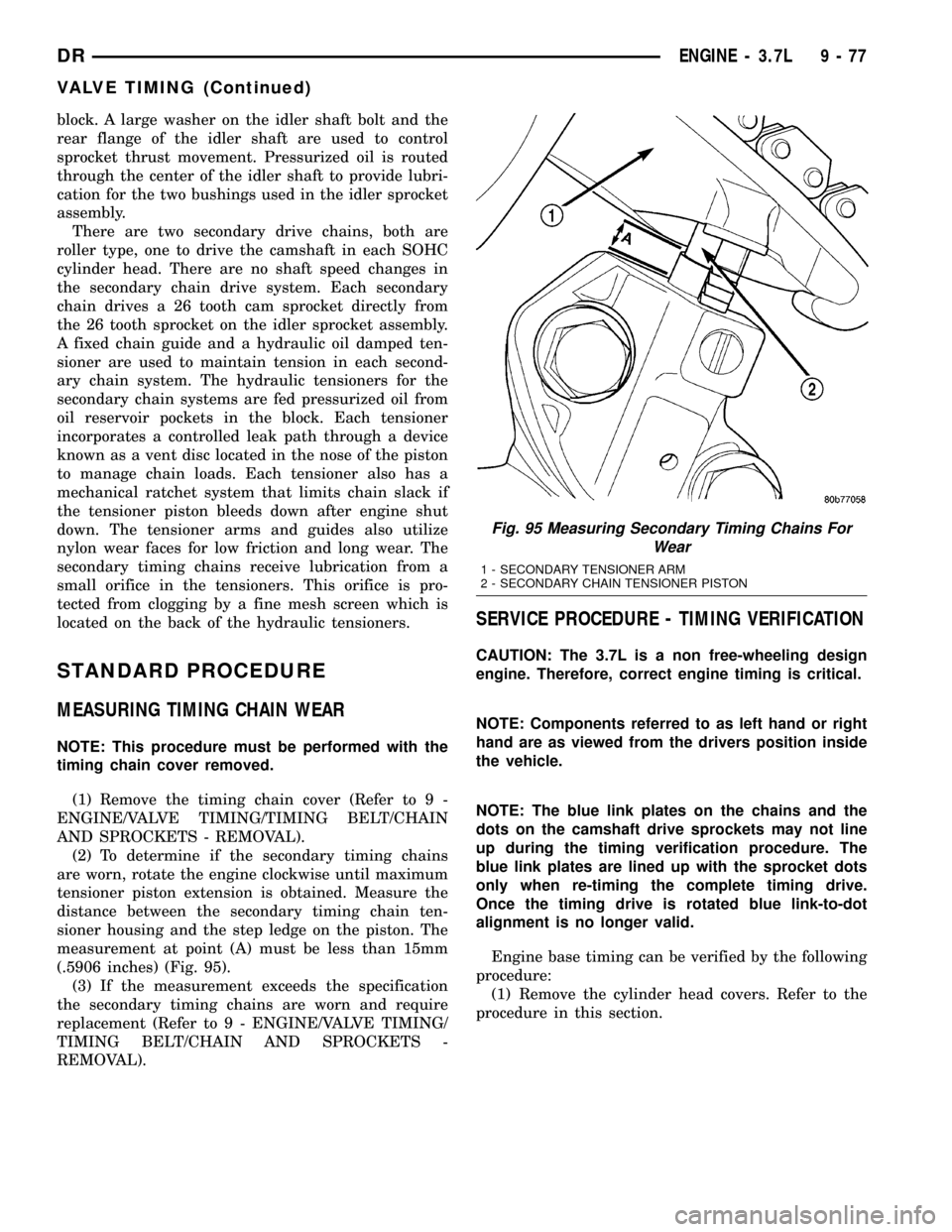
(2) To determine if the secondary timing chains
are worn, rotate the engine clockwise until maximum
tensioner piston extension is obtained. Measure the
distance between the secondary timing chain ten-
sioner housing and the step ledge on the piston. The
measurement at point (A) must be less than 15mm
(.5906 inches) (Fig. 95).
(3) If the measurement exceeds the specification
the secondary timing chains are worn and require
replacement (Refer to 9 - ENGINE/VALVE TIMING/
TIMING BELT/CHAIN AND SPROCKETS -
REMOVAL).
SERVICE PROCEDURE - TIMING VERIFICATION
CAUTION: The 3.7L is a non free-wheeling design
engine. Therefore, correct engine timing is critical.
NOTE: Components referred to as left hand or right
hand are as viewed from the drivers position inside
the vehicle.
NOTE: The blue link plates on the chains and the
dots on the camshaft drive sprockets may not line
up during the timing verification procedure. The
blue link plates are lined up with the sprocket dots
only when re-timing the complete timing drive.
Once the timing drive is rotated blue link-to-dot
alignment is no longer valid.
Engine base timing can be verified by the following
procedure:
(1) Remove the cylinder head covers. Refer to the
procedure in this section.
Fig. 95 Measuring Secondary Timing Chains For
Wear
1 - SECONDARY TENSIONER ARM
2 - SECONDARY CHAIN TENSIONER PISTON
DRENGINE - 3.7L 9 - 77
VALVE TIMING (Continued)