1998 DODGE RAM 1500 car seat
[x] Cancel search: car seatPage 1474 of 2627
(32) Disconnect fuel heater, water in fuel sensor,
and fuel lift pump connectors.
(33) Remove the fuel filter assembly-to-cylinder
head bolts and remove filter assembly from vehicle.
(34) Remove wire harness P-clip from cylinder
head (located behind filter housing).
(35) Remove the cylinder head cover(Refer to 9 -
ENGINE/CYLINDER HEAD/CYLINDER HEAD
COVER(S) - REMOVAL).
(36) Disconnect rocker housing injector harness
connectors.
(37) Remove injector harness nuts from injectors.
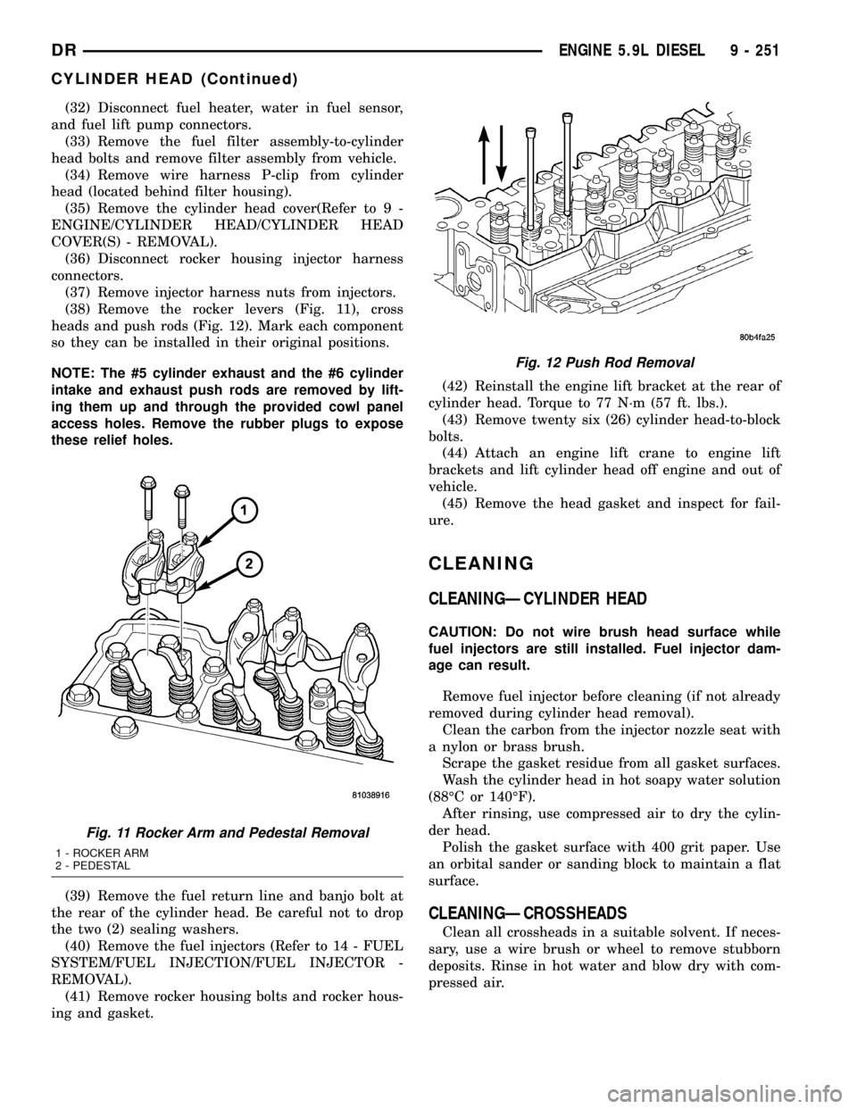
(38) Remove the rocker levers (Fig. 11), cross
heads and push rods (Fig. 12). Mark each component
so they can be installed in their original positions.
NOTE: The #5 cylinder exhaust and the #6 cylinder
intake and exhaust push rods are removed by lift-
ing them up and through the provided cowl panel
access holes. Remove the rubber plugs to expose
these relief holes.
(39) Remove the fuel return line and banjo bolt at
the rear of the cylinder head. Be careful not to drop
the two (2) sealing washers.
(40) Remove the fuel injectors (Refer to 14 - FUEL
SYSTEM/FUEL INJECTION/FUEL INJECTOR -
REMOVAL).
(41) Remove rocker housing bolts and rocker hous-
ing and gasket.(42) Reinstall the engine lift bracket at the rear of
cylinder head. Torque to 77 N´m (57 ft. lbs.).
(43) Remove twenty six (26) cylinder head-to-block
bolts.
(44) Attach an engine lift crane to engine lift
brackets and lift cylinder head off engine and out of
vehicle.
(45) Remove the head gasket and inspect for fail-
ure.
CLEANING
CLEANINGÐCYLINDER HEAD
CAUTION: Do not wire brush head surface while
fuel injectors are still installed. Fuel injector dam-
age can result.
Remove fuel injector before cleaning (if not already
removed during cylinder head removal).
Clean the carbon from the injector nozzle seat with
a nylon or brass brush.
Scrape the gasket residue from all gasket surfaces.
Wash the cylinder head in hot soapy water solution
(88ÉC or 140ÉF).
After rinsing, use compressed air to dry the cylin-
der head.
Polish the gasket surface with 400 grit paper. Use
an orbital sander or sanding block to maintain a flat
surface.
CLEANINGÐCROSSHEADS
Clean all crossheads in a suitable solvent. If neces-
sary, use a wire brush or wheel to remove stubborn
deposits. Rinse in hot water and blow dry with com-
pressed air.
Fig. 11 Rocker Arm and Pedestal Removal
1 - ROCKER ARM
2 - PEDESTAL
Fig. 12 Push Rod Removal
DRENGINE 5.9L DIESEL 9 - 251
CYLINDER HEAD (Continued)
Page 1475 of 2627
CLEANINGÐPUSHRODS
Clean the pushrods in a suitable solvent. Rinse in
hot water and blow dry with compressed air. If nec-
essary, use a wire brush or wheel to remove stubborn
deposits.
INSPECTION
INSPECTION - CYLINDER HEAD
Inspect the cylinder head for cracks in the combus-
tion surface. Pressure test any cylinder head that is
visibly cracked. A cylinder head that is cracked
between the injector bore and valve seat can be pres-
sure tested and reused if OK; however, if the crack
extendsintothe valve seat insert bore, the cylinder
headmustbe replaced.
Visually inspect the cylinder block and head com-
bustion surfaces for localized dips or imperfections.
Check the cylinder head and block combustion sur-
faces for overall out-of-flatness. If either the visual or
manual inspection exceeds the limits, then the head
or block must be surfaced.
Check the top surface for damage caused by the
cylinder head gasket leaking between cylinders.
Inspect the block and head surface for nicks, ero-
sion, etc.
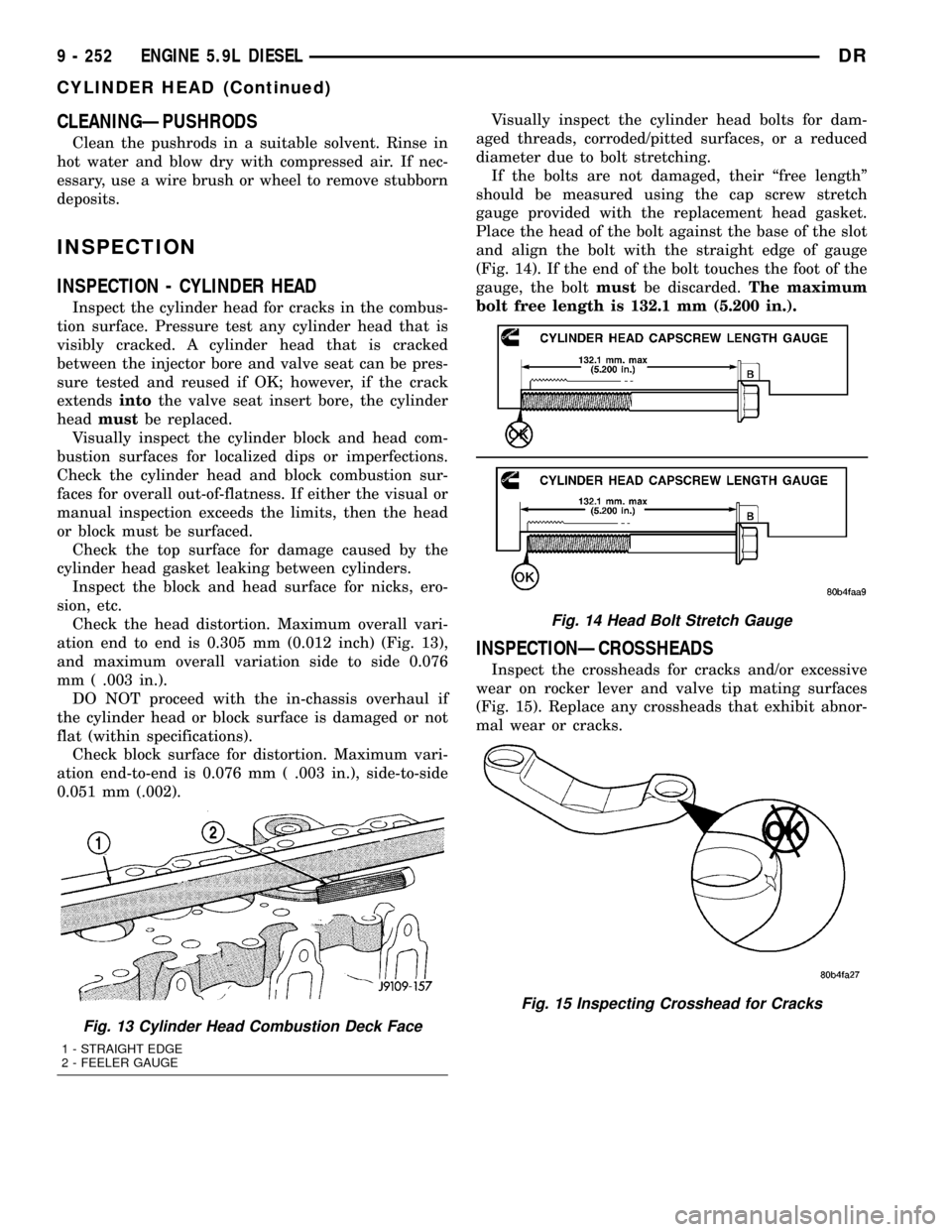
Check the head distortion. Maximum overall vari-
ation end to end is 0.305 mm (0.012 inch) (Fig. 13),
and maximum overall variation side to side 0.076
mm ( .003 in.).
DO NOT proceed with the in-chassis overhaul if
the cylinder head or block surface is damaged or not
flat (within specifications).
Check block surface for distortion. Maximum vari-
ation end-to-end is 0.076 mm ( .003 in.), side-to-side
0.051 mm (.002).Visually inspect the cylinder head bolts for dam-
aged threads, corroded/pitted surfaces, or a reduced
diameter due to bolt stretching.
If the bolts are not damaged, their ªfree lengthº
should be measured using the cap screw stretch
gauge provided with the replacement head gasket.
Place the head of the bolt against the base of the slot
and align the bolt with the straight edge of gauge
(Fig. 14). If the end of the bolt touches the foot of the
gauge, the boltmustbe discarded.The maximum
bolt free length is 132.1 mm (5.200 in.).
INSPECTIONÐCROSSHEADS
Inspect the crossheads for cracks and/or excessive
wear on rocker lever and valve tip mating surfaces
(Fig. 15). Replace any crossheads that exhibit abnor-
mal wear or cracks.
Fig. 13 Cylinder Head Combustion Deck Face
1 - STRAIGHT EDGE
2 - FEELER GAUGE
Fig. 14 Head Bolt Stretch Gauge
Fig. 15 Inspecting Crosshead for Cracks
9 - 252 ENGINE 5.9L DIESELDR
CYLINDER HEAD (Continued)
Page 1476 of 2627
INSPECTIONÐPUSHRODS
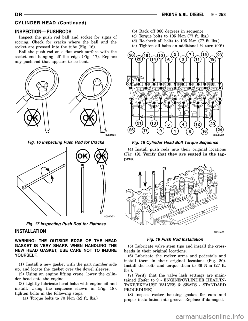
Inspect the push rod ball and socket for signs of
scoring. Check for cracks where the ball and the
socket are pressed into the tube (Fig. 16).
Roll the push rod on a flat work surface with the
socket end hanging off the edge (Fig. 17). Replace
any push rod that appears to be bent.
INSTALLATION
WARNING: THE OUTSIDE EDGE OF THE HEAD
GASKET IS VERY SHARP. WHEN HANDLING THE
NEW HEAD GASKET, USE CARE NOT TO INJURE
YOURSELF.
(1) Install a new gasket with the part number side
up, and locate the gasket over the dowel sleeves.
(2) Using an engine lifting crane, lower the cylin-
der head onto the engine.
(3) Lightly lubricate head bolts with engine oil and
install. Using the sequence shown in (Fig. 18),
tighten bolts in the following steps:
(a) Torque bolts to 70 N´m (52 ft. lbs.)(b) Back off 360 degrees in sequence
(c) Torque bolts to 105 N´m (77 ft. lbs.)
(d) Re-check all bolts to 105 N´m (77 ft. lbs.)
(e) Tighten all bolts an additional
1¤4turn (90É)
(4) Install push rods into their original locations
(Fig. 19).Verify that they are seated in the tap-
pets.
(5) Lubricate valve stem tips and install the cross-
heads in their original locations.
(6) Lubricate the rocker arms and pedestals and
install them in their original locations (Fig. 20).
Install the bolts and torque them to 36 N´m (27 ft.
lbs.).
(7) Verify that the valve lash settings are main-
tained (Refer to 9 - ENGINE/CYLINDER HEAD/IN-
TAKE/EXHAUST VALVES & SEATS - STANDARD
PROCEDURE).
(8) Inspect rocker housing gasket for cuts and
proper installation into groove. Replace if damaged.
Fig. 16 Inspecting Push Rod for Cracks
Fig. 17 Inspecting Push Rod for Flatness
Fig. 18 Cylinder Head Bolt Torque Sequence
Fig. 19 Push Rod Installation
DRENGINE 5.9L DIESEL 9 - 253
CYLINDER HEAD (Continued)
Page 1480 of 2627
(5) Rotate the compressor nut counter-clockwise to
relieve tension on the springs. Remove the spring
compressor.
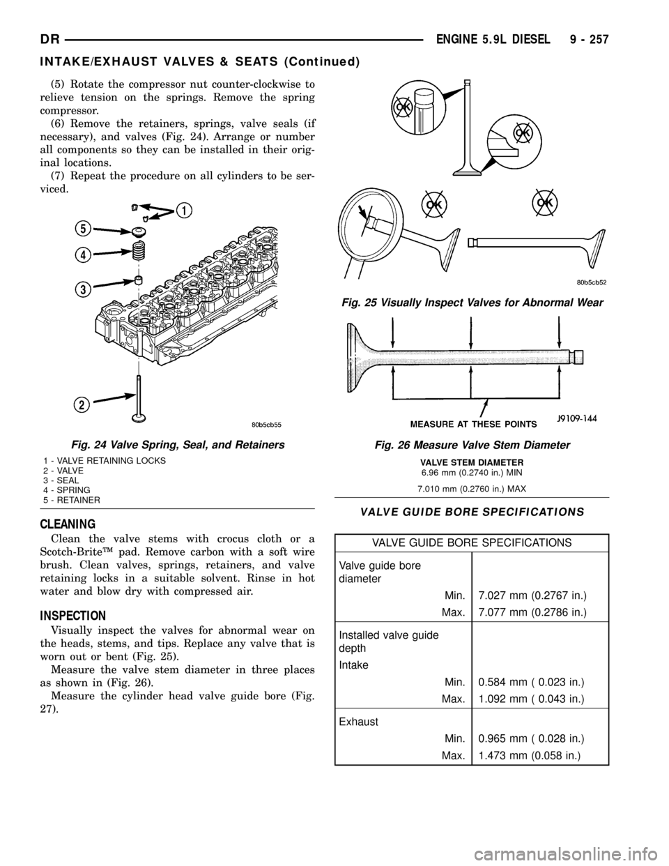
(6) Remove the retainers, springs, valve seals (if
necessary), and valves (Fig. 24). Arrange or number
all components so they can be installed in their orig-
inal locations.
(7) Repeat the procedure on all cylinders to be ser-
viced.
CLEANING
Clean the valve stems with crocus cloth or a
Scotch-BriteŸ pad. Remove carbon with a soft wire
brush. Clean valves, springs, retainers, and valve
retaining locks in a suitable solvent. Rinse in hot
water and blow dry with compressed air.
INSPECTION
Visually inspect the valves for abnormal wear on
the heads, stems, and tips. Replace any valve that is
worn out or bent (Fig. 25).
Measure the valve stem diameter in three places
as shown in (Fig. 26).
Measure the cylinder head valve guide bore (Fig.
27).
VALVE GUIDE BORE SPECIFICATIONS
VALVE GUIDE BORE SPECIFICATIONS
Valve guide bore
diameter
Min. 7.027 mm (0.2767 in.)
Max. 7.077 mm (0.2786 in.)
Installed valve guide
depth
Intake
Min. 0.584 mm ( 0.023 in.)
Max. 1.092 mm ( 0.043 in.)
Exhaust
Min. 0.965 mm ( 0.028 in.)
Max. 1.473 mm (0.058 in.)
Fig. 24 Valve Spring, Seal, and Retainers
1 - VALVE RETAINING LOCKS
2 - VALVE
3 - SEAL
4 - SPRING
5 - RETAINER
Fig. 25 Visually Inspect Valves for Abnormal Wear
Fig. 26 Measure Valve Stem Diameter
VALVE STEM DIAMETER
6.96 mm (0.2740 in.) MIN
7.010 mm (0.2760 in.) MAX
DRENGINE 5.9L DIESEL 9 - 257
INTAKE/EXHAUST VALVES & SEATS (Continued)
Page 1492 of 2627
(15) Remove the two charge air cooler mounting
bolts.
(16) Remove charge air cooler (and A/C condenser
if equipped) from vehicle.
(17) Remove accessory drive belt (Refer to 7 -
COOLING/ACCESSORY DRIVE/DRIVE BELTS -
REMOVAL).
(18) Remove accessory drive belt tensioner.
(19) Remove the fan support/hub assembly.
(20) Remove crankshaft damper and speed indica-
tor ring (Refer to 9 - ENGINE/ENGINE BLOCK/VI-
BRATION DAMPER - REMOVAL).
(21) Remove the gear cover-to-housing bolts and
gently pry the cover away from the housing, taking
care not to mar the sealing surfaces. Remove dust
seal with cover.
(22) Using Special Tool 7471±B Crankshaft Bar-
ring Tool, rotate the crankshaft to align the timing
marks on the crankshaft and the camshaft gears.
(23) Remove the cylinder head cover (Refer to 9 -
ENGINE/CYLINDER HEAD/CYLINDER HEAD
COVER(S) - REMOVAL).
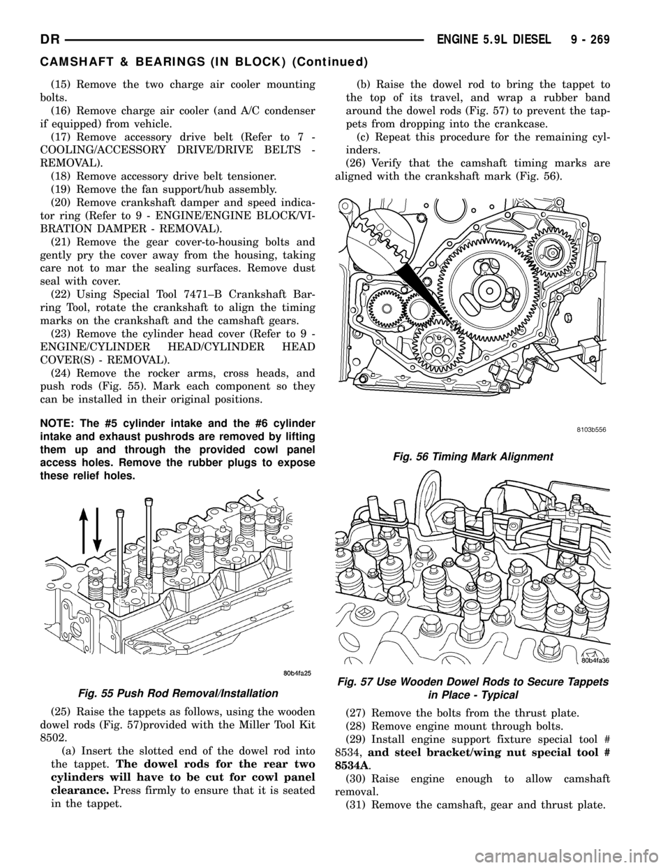
(24) Remove the rocker arms, cross heads, and
push rods (Fig. 55). Mark each component so they
can be installed in their original positions.
NOTE: The #5 cylinder intake and the #6 cylinder
intake and exhaust pushrods are removed by lifting
them up and through the provided cowl panel
access holes. Remove the rubber plugs to expose
these relief holes.
(25) Raise the tappets as follows, using the wooden
dowel rods (Fig. 57)provided with the Miller Tool Kit
8502.
(a) Insert the slotted end of the dowel rod into
the tappet.The dowel rods for the rear two
cylinders will have to be cut for cowl panel
clearance.Press firmly to ensure that it is seated
in the tappet.(b) Raise the dowel rod to bring the tappet to
the top of its travel, and wrap a rubber band
around the dowel rods (Fig. 57) to prevent the tap-
pets from dropping into the crankcase.
(c) Repeat this procedure for the remaining cyl-
inders.
(26) Verify that the camshaft timing marks are
aligned with the crankshaft mark (Fig. 56).
(27) Remove the bolts from the thrust plate.
(28) Remove engine mount through bolts.
(29) Install engine support fixture special tool #
8534,and steel bracket/wing nut special tool #
8534A.
(30) Raise engine enough to allow camshaft
removal.
(31) Remove the camshaft, gear and thrust plate.
Fig. 55 Push Rod Removal/Installation
Fig. 56 Timing Mark Alignment
Fig. 57 Use Wooden Dowel Rods to Secure Tappets
in Place - Typical
DRENGINE 5.9L DIESEL 9 - 269
CAMSHAFT & BEARINGS (IN BLOCK) (Continued)
Page 1515 of 2627
OIL
STANDARD PROCEDURE
STANDARD PROCEDURE - ENGINE OIL LEVEL
CAUTION: Do not overfill crankcase with engine oil,
oil foaming and oil pressure loss can result.
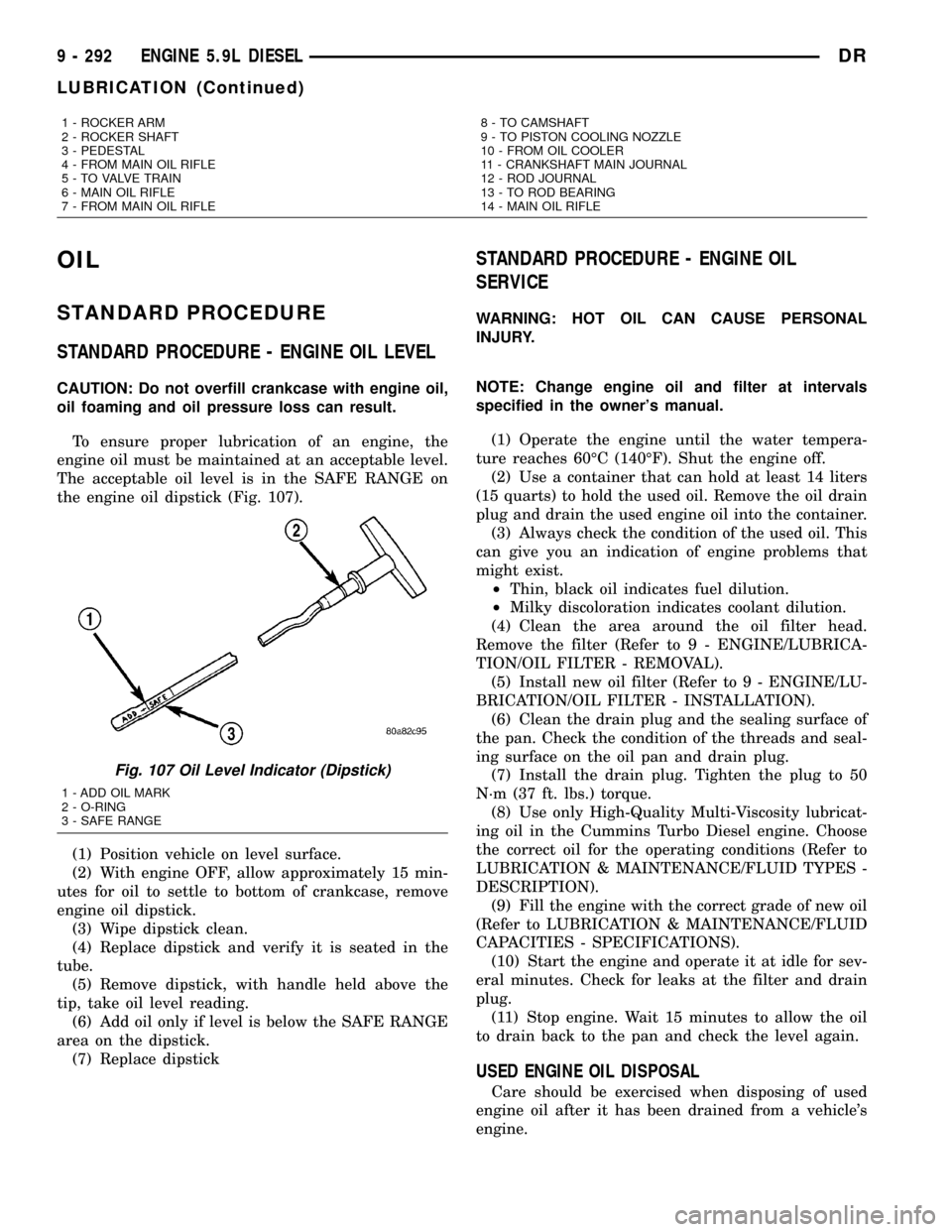
To ensure proper lubrication of an engine, the
engine oil must be maintained at an acceptable level.
The acceptable oil level is in the SAFE RANGE on
the engine oil dipstick (Fig. 107).
(1) Position vehicle on level surface.
(2) With engine OFF, allow approximately 15 min-
utes for oil to settle to bottom of crankcase, remove
engine oil dipstick.
(3) Wipe dipstick clean.
(4) Replace dipstick and verify it is seated in the
tube.
(5) Remove dipstick, with handle held above the
tip, take oil level reading.
(6) Add oil only if level is below the SAFE RANGE
area on the dipstick.
(7) Replace dipstick
STANDARD PROCEDURE - ENGINE OIL
SERVICE
WARNING: HOT OIL CAN CAUSE PERSONAL
INJURY.
NOTE: Change engine oil and filter at intervals
specified in the owner's manual.
(1) Operate the engine until the water tempera-
ture reaches 60ÉC (140ÉF). Shut the engine off.
(2) Use a container that can hold at least 14 liters
(15 quarts) to hold the used oil. Remove the oil drain
plug and drain the used engine oil into the container.
(3) Always check the condition of the used oil. This
can give you an indication of engine problems that
might exist.
²Thin, black oil indicates fuel dilution.
²Milky discoloration indicates coolant dilution.
(4) Clean the area around the oil filter head.
Remove the filter (Refer to 9 - ENGINE/LUBRICA-
TION/OIL FILTER - REMOVAL).
(5) Install new oil filter (Refer to 9 - ENGINE/LU-
BRICATION/OIL FILTER - INSTALLATION).
(6) Clean the drain plug and the sealing surface of
the pan. Check the condition of the threads and seal-
ing surface on the oil pan and drain plug.
(7) Install the drain plug. Tighten the plug to 50
N´m (37 ft. lbs.) torque.
(8) Use only High-Quality Multi-Viscosity lubricat-
ing oil in the Cummins Turbo Diesel engine. Choose
the correct oil for the operating conditions (Refer to
LUBRICATION & MAINTENANCE/FLUID TYPES -
DESCRIPTION).
(9) Fill the engine with the correct grade of new oil
(Refer to LUBRICATION & MAINTENANCE/FLUID
CAPACITIES - SPECIFICATIONS).
(10) Start the engine and operate it at idle for sev-
eral minutes. Check for leaks at the filter and drain
plug.
(11) Stop engine. Wait 15 minutes to allow the oil
to drain back to the pan and check the level again.
USED ENGINE OIL DISPOSAL
Care should be exercised when disposing of used
engine oil after it has been drained from a vehicle's
engine.
1 - ROCKER ARM
2 - ROCKER SHAFT
3 - PEDESTAL
4 - FROM MAIN OIL RIFLE
5 - TO VALVE TRAIN
6 - MAIN OIL RIFLE
7 - FROM MAIN OIL RIFLE8 - TO CAMSHAFT
9 - TO PISTON COOLING NOZZLE
10 - FROM OIL COOLER
11 - CRANKSHAFT MAIN JOURNAL
12 - ROD JOURNAL
13 - TO ROD BEARING
14 - MAIN OIL RIFLE
Fig. 107 Oil Level Indicator (Dipstick)
1 - ADD OIL MARK
2 - O-RING
3 - SAFE RANGE
9 - 292 ENGINE 5.9L DIESELDR
LUBRICATION (Continued)
Page 1545 of 2627
FRONT AIR DAM
REMOVAL
(1) Remove the two outboard screws.
(2) Remove the three middle screws and remove
the air dam.
INSTALLATION
(1) Position the air dam onto the bumper and seat
the carrot type fasteners fully.
(2) Starting at the center screw install the three
middle screws.
(3) Install the two outboard screws.
FRONT BUMPER
REMOVAL
(1) Using a grease pencil or equivalent, mark the
position of the bumper on the frame rail tip to aid
installation.
(2) Disconnect the fog lamp electrical connector at
the left frame rail.
(3) Support the bumper with a suitable lifting
device.
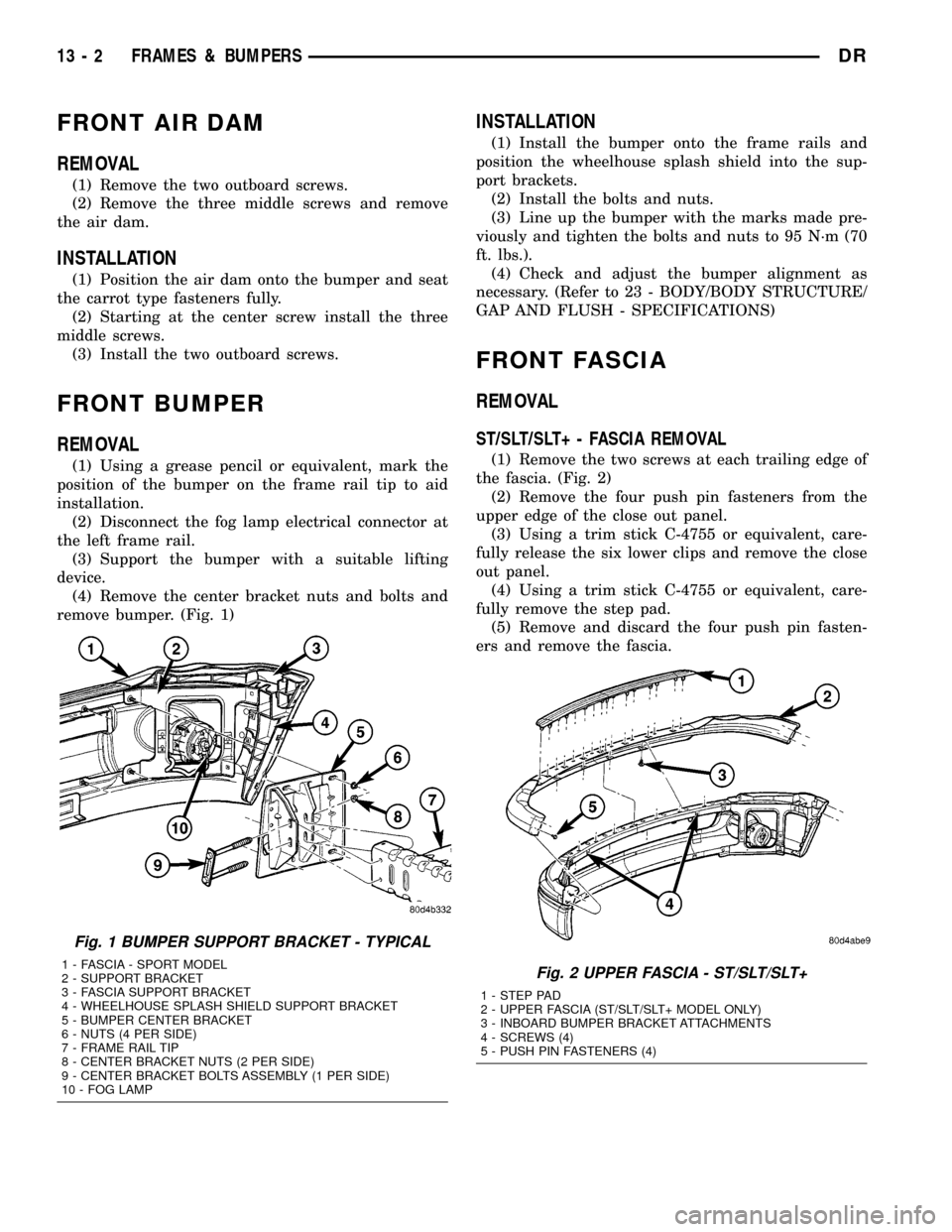
(4) Remove the center bracket nuts and bolts and
remove bumper. (Fig. 1)
INSTALLATION
(1) Install the bumper onto the frame rails and
position the wheelhouse splash shield into the sup-
port brackets.
(2) Install the bolts and nuts.
(3) Line up the bumper with the marks made pre-
viously and tighten the bolts and nuts to 95 N´m (70
ft. lbs.).
(4) Check and adjust the bumper alignment as
necessary. (Refer to 23 - BODY/BODY STRUCTURE/
GAP AND FLUSH - SPECIFICATIONS)
FRONT FASCIA
REMOVAL
ST/SLT/SLT+ - FASCIA REMOVAL
(1) Remove the two screws at each trailing edge of
the fascia. (Fig. 2)
(2) Remove the four push pin fasteners from the
upper edge of the close out panel.
(3) Using a trim stick C-4755 or equivalent, care-
fully release the six lower clips and remove the close
out panel.
(4) Using a trim stick C-4755 or equivalent, care-
fully remove the step pad.
(5) Remove and discard the four push pin fasten-
ers and remove the fascia.
Fig. 1 BUMPER SUPPORT BRACKET - TYPICAL
1 - FASCIA - SPORT MODEL
2 - SUPPORT BRACKET
3 - FASCIA SUPPORT BRACKET
4 - WHEELHOUSE SPLASH SHIELD SUPPORT BRACKET
5 - BUMPER CENTER BRACKET
6 - NUTS (4 PER SIDE)
7 - FRAME RAIL TIP
8 - CENTER BRACKET NUTS (2 PER SIDE)
9 - CENTER BRACKET BOLTS ASSEMBLY (1 PER SIDE)
10 - FOG LAMPFig. 2 UPPER FASCIA - ST/SLT/SLT+
1 - STEP PAD
2 - UPPER FASCIA (ST/SLT/SLT+ MODEL ONLY)
3 - INBOARD BUMPER BRACKET ATTACHMENTS
4 - SCREWS (4)
5 - PUSH PIN FASTENERS (4)
13 - 2 FRAMES & BUMPERSDR
Page 1546 of 2627
SPORT FASCIA REMOVAL
(1) Raise and support the vehicle. (Refer to
LUBRICATION & MAINTENANCE/HOISTING -
STANDARD PROCEDURE)
(2) Remove the three screws at each trailing edge
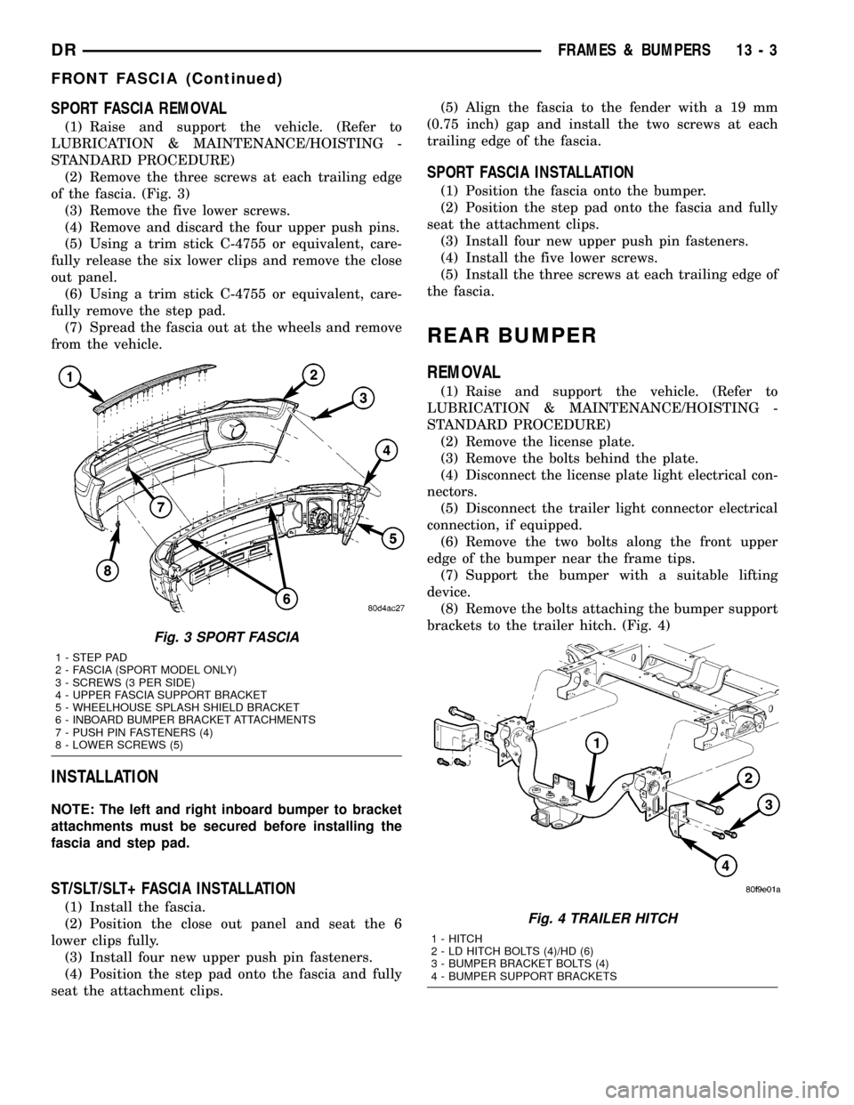
of the fascia. (Fig. 3)
(3) Remove the five lower screws.
(4) Remove and discard the four upper push pins.
(5) Using a trim stick C-4755 or equivalent, care-
fully release the six lower clips and remove the close
out panel.
(6) Using a trim stick C-4755 or equivalent, care-
fully remove the step pad.
(7) Spread the fascia out at the wheels and remove
from the vehicle.
INSTALLATION
NOTE: The left and right inboard bumper to bracket
attachments must be secured before installing the
fascia and step pad.
ST/SLT/SLT+ FASCIA INSTALLATION
(1) Install the fascia.
(2) Position the close out panel and seat the 6
lower clips fully.
(3) Install four new upper push pin fasteners.
(4) Position the step pad onto the fascia and fully
seat the attachment clips.(5) Align the fascia to the fender with a 19 mm
(0.75 inch) gap and install the two screws at each
trailing edge of the fascia.
SPORT FASCIA INSTALLATION
(1) Position the fascia onto the bumper.
(2) Position the step pad onto the fascia and fully
seat the attachment clips.
(3) Install four new upper push pin fasteners.
(4) Install the five lower screws.
(5) Install the three screws at each trailing edge of
the fascia.
REAR BUMPER
REMOVAL
(1) Raise and support the vehicle. (Refer to
LUBRICATION & MAINTENANCE/HOISTING -
STANDARD PROCEDURE)
(2) Remove the license plate.
(3) Remove the bolts behind the plate.
(4) Disconnect the license plate light electrical con-
nectors.
(5) Disconnect the trailer light connector electrical
connection, if equipped.
(6) Remove the two bolts along the front upper
edge of the bumper near the frame tips.
(7) Support the bumper with a suitable lifting
device.
(8) Remove the bolts attaching the bumper support
brackets to the trailer hitch. (Fig. 4)
Fig. 3 SPORT FASCIA
1 - STEP PAD
2 - FASCIA (SPORT MODEL ONLY)
3 - SCREWS (3 PER SIDE)
4 - UPPER FASCIA SUPPORT BRACKET
5 - WHEELHOUSE SPLASH SHIELD BRACKET
6 - INBOARD BUMPER BRACKET ATTACHMENTS
7 - PUSH PIN FASTENERS (4)
8 - LOWER SCREWS (5)
Fig. 4 TRAILER HITCH
1 - HITCH
2 - LD HITCH BOLTS (4)/HD (6)
3 - BUMPER BRACKET BOLTS (4)
4 - BUMPER SUPPORT BRACKETS
DRFRAMES & BUMPERS 13 - 3
FRONT FASCIA (Continued)