1998 DODGE RAM 1500 car seat
[x] Cancel search: car seatPage 1402 of 2627
IDLER SHAFT
REMOVAL
(1) Remove the primary and secondary timing
chains and sprockets (Refer to 9 - ENGINE/VALVE
TIMING/TIMING BELT/CHAIN AND SPROCKETS -
REMOVAL).
NOTE: To remove the idler shaft, it is necessary to
tap threads into the shaft, to install the removal
tool.
(2) Using a 12 mm X 1.75 tap, cut threads in the
idler shaft center bore.
(3) Cover the radiator core with a suitable cover.
CAUTION: Use care when removing the idler shaft,
Do not strike the radiator cooling fins with the slide
hammer.
(4) Using Special Tool 8517 Slide Hammer, remove
the idler shaft.
INSTALLATION
(1) Thoroughly clean the idler shaft bore.
(2) Position the idler shaft in the bore.
NOTE: The two lubrication holes in the idler shaft
do not require any special alignment.
NOTE: Before using the retaining bolt to install the
idler shaft, coat the threads and the pilot on the
idler shaft, with clean engine oil.
(3) Using the primary idler sprocket retaining bolt
and washer, carefully draw the idler shaft into the
bore until fully seated.
(4) Coat the idler shaft with clean engine oil.
(5) Install the timing chains and sprockets (Refer
to 9 - ENGINE/VALVE TIMING/TIMING BELT/
CHAIN AND SPROCKETS - INSTALLATION).
DRENGINE - 4.7L 9 - 179
Page 1423 of 2627
þ Loss of engine power
þ Engine misfiring
þ Poor fuel economy
²Possible indications of the cylinder head gasket
leaking between a cylinder and an adjacent water
jacket are:
þ Engine overheating
þ Loss of coolant
þ Excessive steam (white smoke) emitting from
exhaust
þ Coolant foaming
CYLINDER-TO-CYLINDER LEAKAGE TEST
To determine if an engine cylinder head gasket is
leaking between adjacent cylinders, follow the proce-
dures in Cylinder Compression Pressure Test in this
section. An engine cylinder head gasket leaking
between adjacent cylinders will result in approxi-
mately a 50±70% reduction in compression pressure.
CYLINDER-TO-WATER JACKET LEAKAGE TEST
WARNING: USE EXTREME CAUTION WHEN THE
ENGINE IS OPERATING WITH COOLANT PRES-
SURE CAP REMOVED.
VISUAL TEST METHOD
With the engine cool, remove the coolant pressure
cap. Start the engine and allow it to warm up until
thermostat opens.
If a large combustion/compression pressure leak
exists, bubbles will be visible in the coolant.
COOLING SYSTEM TESTER METHOD
WARNING: WITH COOLING SYSTEM TESTER IN
PLACE, PRESSURE WILL BUILD UP FAST. EXCES-
SIVE PRESSURE BUILT UP, BY CONTINUOUS
ENGINE OPERATION, MUST BE RELEASED TO A
SAFE PRESSURE POINT. NEVER PERMIT PRES-
SURE TO EXCEED 138 kPa (20 psi).
Install Cooling System Tester 7700 or equivalent to
pressure cap neck. Start the engine and observe the
tester's pressure gauge. If gauge pulsates with every
power stroke of a cylinder a combustion pressure
leak is evident.
CHEMICAL TEST METHOD
Combustion leaks into the cooling system can also
be checked by using Bloc-Chek Kit C-3685-A or
equivalent. Perform test following the procedures
supplied with the tool kit.
REMOVAL
(1) Disconnect the battery negative cable.
(2) Drain cooling system.
(3) Remove the air cleaner resonator and duct
work.
(4) Remove the generator.
(5) Remove closed crankcase ventilation system.
(6) Disconnect the evaporation control system.
(7) Perform the Fuel System Pressure Release pro-
cedure (Refer to 14 - FUEL SYSTEM/FUEL DELIV-
ERY - STANDARD PROCEDURE). Disconnect the
fuel supply line (Refer to 14 - FUEL SYSTEM/FUEL
DELIVERY/QUICK CONNECT FITTING - STAN-
DARD PROCEDURE).
(8) Disconnect heater hoses.
(9) Remove cylinder head covers and gaskets.
(10) Remove intake manifold and throttle body as
an assembly.
(11) Remove rocker arm assemblies and push rods.
Identify to ensure installation in original locations.
(12) Remove the head bolts from each cylinder
head and remove cylinder heads. Discard the cylin-
der head gasket.
CLEANING
Clean all surfaces of cylinder block and cylinder
heads.
Clean cylinder block front and rear gasket surfaces
using a suitable solvent.
INSPECTION
(1) Inspect the cylinder head for out-of-flatness,
using a straightedge and a feeler gauge. If tolerances
exceed 0.0508 mm (0.002 in.) replace the cylinder
head.
(2) Inspect the valve seats for damage. Service the
valve seats as necessary.
(3) Inspect the valve guides for wear, cracks or
looseness. If either condition exist, replace the cylin-
der head.
(4) Inspect pushrods. Replace worn or bent push-
rods.
INSTALLATION
(1) Clean all surfaces of cylinder block and cylin-
der heads.
(2) Clean cylinder block front and rear gasket sur-
faces using a suitable solvent.
CAUTION: The head gaskets are not interchange-
able between left and right sides. They are marked
ªLº and ªRº to indicate left and right sides.
(3) Position new cylinder head gaskets onto the
cylinder block.
9 - 200 ENGINE - 5.7LDR
CYLINDER HEAD (Continued)
Page 1426 of 2627
REMOVAL
(1) Remove the cylinder head (Refer to 9 -
ENGINE/CYLINDER HEAD - REMOVAL).
(2) Compress valve springs using Valve Spring
Compressor Tool special tool # C-3422and adapter
8464.
(3) Remove valve retaining locks, valve spring
retainers, valve stem seals and valve springs.
(4) Before removing valves, remove any burrs from
valve stem lock grooves to prevent damage to the
valve guides. Identify valves to ensure installation in
original location.
INSTALLATION
(1) Clean valves thoroughly. Discard burned,
warped and cracked valves.
(2) Remove carbon and varnish deposits from
inside of valve guides with a reliable guide cleaner.
(3) Measure valve stems for wear. If wear exceeds
0.051 mm (0.002 inch), replace the valve.
(4) Coat valve stems with lubrication oil and insert
them in cylinder head.
(5) If valves or seats are reground, check valve
stem height. If valve is too long, replace cylinder
head.
(6) Install new seals on all valve guides. Install
valve springs and valve retainers.
(7) Compress valve springs with Valve Spring
Compressor Tool special tool # C- 3422and adapter
8464, install locks and release tool. If valves and/or
seats are ground, measure the installed height of
springs. Make sure the measurement is taken from
bottom of spring seat in cylinder head to the bottom
surface of spring retainer.
(8) Install cylinder head (Refer to 9 - ENGINE/
CYLINDER HEAD - INSTALLATION).
ROCKER ARM / ADJUSTER
ASSY
REMOVAL
(1) Remove cylinder head cover.(Refer to 9 -
ENGINE/CYLINDER HEAD/CYLINDER HEAD
COVER(S) - REMOVAL)
(2) Loosen the rocker shafts using the following
sequence:Center, center-left, center-right, left,
right,.
CAUTION: The rocker shaft assemblies are not
interchangeable between intake and exhaust. The
intake rocker arms are marked with an ªIº.
(3) Remove the rocker shafts. Note location for
reassembly.CAUTION: The longer push rods are for the exhaust
side, and the shorter push rods are for intake side.
(4) Remove the pushrods. Note pushrod location
for reassembly.
INSTALLATION
CAUTION: The longer push rods are for the exhaust
side, and the shorter push rods are for intake side.
(1) Install the push rods in the same order as
removed.
CAUTION: Verify that pushrod is installed into
rocker arm and lifter correctly while installing
rocker shaft assembly. Recheck after rocker shaft
has been torqued to specification.
CAUTION: The rocker shaft assemblies are not
interchangeable between intake and exhaust. The
intake rocker arms are marked with the letter ªIº.
(2) Install rocker shaft assemblies in the same
order as removed.
CAUTION: Ensure that hold downs and rocker arms
are not overlapped when torquing bolts.
(3) Tighten the rocker shaft bolts to 22 N´m (195
in. lbs.) torque,using the following sequence:Center,
center-right, center-left, right, left.
CAUTION: DO NOT rotate or crank the engine dur-
ing or immediately after rocker arm installation.
Allow the hydraulic roller tappets adequate time to
bleed down (about 5 minutes).
(4) Install cylinder head cover (Refer to 9 -
ENGINE/CYLINDER HEAD/CYLINDER HEAD
COVER(S) - INSTALLATION).
VALVE STEM SEALS
DESCRIPTION
The valve guide seals are made of rubber and
incorporate an integral steel valve spring seat. The
integral garter spring maintains consistent lubrica-
tion control to the valve stems.
DRENGINE - 5.7L 9 - 203
INTAKE/EXHAUST VALVES & SEATS (Continued)
Page 1432 of 2627
CRANKSHAFT OIL SEAL -
REAR
DIAGNOSIS AND TESTING - REAR SEAL AREA
LEAKS
Since it is sometimes difficult to determine the
source of an oil leak in the rear seal area of the
engine, a more involved inspection is necessary. The
following steps should be followed to help pinpoint
the source of the leak.
If the leakage occurs at the crankshaft rear oil seal
area:
(1) Disconnect the battery.
(2) Raise the vehicle.
(3) Remove torque converter or clutch housing
cover and inspect rear of block for evidence of oil.
Use a black light to check for the oil leak:
(a) Circular spray pattern generally indicates
seal leakage or crankshaft damage.
(b) Where leakage tends to run straight down,
possible causes are a porous block, camshaft bore
cup plugs, oil galley pipe plugs, oil filter runoff,
and main bearing cap to cylinder block mating sur-
faces. See Engine, for proper repair procedures of
these items.
(4) If no leaks are detected, pressurized the crank-
case as outlined in the section, Inspection (Engine oil
Leaks in general)
CAUTION: Do not exceed 20.6 kPa (3 psi).
(5) If the leak is not detected, very slowly turn the
crankshaft and watch for leakage. If a leak is
detected between the crankshaft and seal while
slowly turning the crankshaft, it is possible the
crankshaft seal surface is damaged. The seal area on
the crankshaft could have minor nicks or scratches
that can be polished out with emery cloth.
CAUTION: Use extreme caution when crankshaft
polishing is necessary to remove minor nicks or
scratches. The crankshaft seal flange is specially
machined to complement the function of the rear oil
seal.
(6) For bubbles that remain steady with shaft
rotation, no further inspection can be done until dis-
assembled. (Refer to 9 - ENGINE - DIAGNOSIS AND
TESTING), under the Oil Leak row, for components
inspections on possible causes and corrections.
(7) After the oil leak root cause and appropriate
corrective action have been identified, (Refer to 9 -
ENGINE/ENGINE BLOCK/CRANKSHAFT OIL
SEAL - REAR - REMOVAL).
REMOVAL
NOTE: This procedure can be performed in vehicle.
(1) If being preformed in vehicle, remove the
transmission.
(2) Remove the flexplate (Refer to 9 - ENGINE/
ENGINE BLOCK/FLEX PLATE - REMOVAL).
NOTE: The crankshaft oil seal CAN NOT be reused
after removal.
NOTE: The crankshaft rear oil seal remover Special
Tool 8506 must be installed deeply into the seal.
Continue to tighten the removal tool into the seal
until the tool can not be turned farther. Failure to
install tool correctly the first time will cause tool to
pull free of seal without removing seal from engine.
(3) Using Special Tool 8506, remove the crankshaft
rear oil seal.
INSTALLATION
CAUTION: The rear seal must be installed dry for
proper operation. Do not lubricate the seal lip or
outer edge.
(1) Position the plastic seal guide onto the crank-
shaft rear face. Then position the crankshaft rear oil
seal onto the guide.
(2) Using Special Tools 8349 Crankshaft Rear Oil
Seal Installer and C-4171 Driver Handle, with a
hammer, tap the seal into place. Continue to tap on
the driver handle until the seal installer seats
against the cylinder block crankshaft bore.
(3) Install the flexplate.
(4) Install the transmission.
CRANKSHAFT REAR OIL SEAL
RETAINER
REMOVAL
(1) Disconnect negative cable from battery.
(2) Remove the transmission.
(3) Remove the drive plate / flywheel.
(4) Remove the oil pan (Refer to 9 - ENGINE/LU-
BRICATION/OIL PAN - REMOVAL).
(5) Remove the rear oil seal retainer mounting
bolts.
(6) Carefully remove the retainer from the engine
block.
DRENGINE - 5.7L 9 - 209
Page 1433 of 2627
INSTALLATION
(1) Throughly clean all gasket resdue from the
engine block.
(2) Use extream care and clean all gasket resdue
from the retainer.
(3) Position the gasket onto the retainer.
(4) Position the retainer onto the engine block.
(5) Install the retainer mounting bolts. Tighten the
bolts to 15 N´m (132 in. lbs.) using a crisscross pat-
tern, starting with the bolt on the lower right.
(6) Install a new rear seal(Refer to 9 - ENGINE/
ENGINE BLOCK/CRANKSHAFT OIL SEAL - REAR
- INSTALLATION).
(7) Install the oil pan (Refer to 9 - ENGINE/LU-
BRICATION/OIL PAN - INSTALLATION).
(8) Install the drive plate / flywheel.
(9) Install the transmission.
(10) Check and verify engine oil level.
(11) Start engine and check for leaks.
FLEX PLATE
REMOVAL
(1) Remove the transmission.
(2) Remove the bolts and flexplate.
INSTALLATION
(1) Position the flexplate or flywheel onto the
crankshaft and install the bolts hand tight.
(2)For automatic transmissions:Tighten the
flexplate retaining bolts to 95 N´m (70 ft. lbs.).
(3)For manual transmissions:Tighten the fly-
wheel retaining bolts to 75 N´m (55 ft. lbs.).
(4) Install the transmission.
HYDRAULIC TAPPETS
DIAGNOSIS AND TESTING - HYDRAULIC
TAPPETS
Before disassembling any part of the engine to cor-
rect tappet noise, check the oil pressure. If vehicle
has no oil pressure gauge, install a reliable gauge at
the pressure sending-unit. The pressure should be
between 207-552 kPa (30-70 psi) at 3,000 RPM.
Check the oil level after the engine reaches normal
operating temperature. Allow 5 minutes to stabilize
oil level, check dipstick. The oil level in the pan
should never be above the FULL mark or below the
ADD OIL mark on dipstick. Either of these two con-
ditions could be responsible for noisy tappets.
OIL LEVEL
HIGH
If oil level is above the FULL mark, it is possible
for the connecting rods to dip into the oil. With the
engine running, this condition could create foam in
the oil pan. Foam in oil pan would be fed to the
hydraulic tappets by the oil pump causing them to
lose length and allow valves to seat noisily.
LOW
Low oil level may allow oil pump to take in air. When
air is fed to the tappets, they lose length, which allows
valves to seat noisily. Any leaks on intake side of oil
pump through which air can be drawn will create the
same tappet action. Check the lubrication system from
the intake strainer to the pump cover, including the
relief valve retainer cap. When tappet noise is due to
aeration, it may be intermittent or constant, and usu-
ally more than one tappet will be noisy. When oil level
and leaks have been corrected, operate the engine at
fast idle. Run engine for a sufficient time to allow all of
the air inside the tappets to be bled out.
TAPPET NOISE DIAGNOSIS
(1) To determine source of tappet noise, operate
engine at idle with cylinder head covers removed.
(2) Feel each valve spring or rocker arm to detect
noisy tappet. The noisy tappet will cause the affected
spring and/or rocker arm to vibrate or feel rough in
operation.
NOTE: Worn valve guides or cocked springs are
sometimes mistaken for noisy tappets. If such is
the case, noise may be dampened by applying side
thrust on the valve spring. If noise is not apprecia-
bly reduced, it can be assumed the noise is in the
tappet. Inspect the rocker arm push rod sockets
and push rod ends for wear.
(3)
Valve tappet noise ranges from light noise to a
heavy click. A light noise is usually caused by excessive
leak-down around the unit plunger, or by the plunger
partially sticking in the tappet body cylinder. The tap-
pet should be replaced. A heavy click is caused by a tap-
pet check valve not seating, or by foreign particles
wedged between the plunger and the tappet body. This
will cause the plunger to stick in the down position.
This heavy click will be accompanied by excessive clear-
ance between the valve stem and rocker arm as valve
closes. In either case, tappet assembly should be
removed for inspection and cleaning.
(4) The valve train generates a noise very much
like a light tappet noise during normal operation.
Care must be taken to ensure that tappets are mak-
ing the noise. If more than one tappet seems to be
noisy, it's probably not the tappets.
9 - 210 ENGINE - 5.7LDR
CRANKSHAFT REAR OIL SEAL RETAINER (Continued)
Page 1446 of 2627
minutes before checking oil level. Checking engine oil
level on a cold engine is not accurate.
To ensure proper lubrication of an engine, the
engine oil must be maintained at an acceptable level.
The acceptable levels are indicated between the ADD
and SAFE marks on the engine oil dipstick.
(1) Position vehicle on level surface.
(2) With engine OFF, allow approximately five
minutes for oil to settle to bottom of crankcase,
remove engine oil dipstick.
(3) Wipe dipstick clean.
(4) Install dipstick and verify it is seated in the
tube.
(5) Remove dipstick, with handle held above the
tip, take oil level reading.
(6) Add oil only if level is below the ADD mark on
dipstick.
ENGINE OIL CHANGE
Change engine oil at mileage and time intervals
described in Maintenance Schedules(Refer to LUBRI-
CATION & MAINTENANCE/MAINTENANCE
SCHEDULES - DESCRIPTION).
Run engine until achieving normal operating tem-
perature.
(1) Position the vehicle on a level surface and turn
engine off.
(2) Hoist and support vehicle on safety stands.
(3) Remove oil fill cap.
(4) Place a suitable drain pan under crankcase
drain.
(5) Remove drain plug from crankcase and allow
oil to drain into pan. Inspect drain plug threads for
stretching or other damage. Replace drain plug if
damaged.
(6) Install drain plug in crankcase. Torque to 34
N´m ( 25 ft. lbs.).
(7) Lower vehicle and fill crankcase with specified
type and amount of engine oil described in this sec-
tion.
(8) Install oil fill cap.
(9) Start engine and inspect for leaks.
(10) Stop engine and inspect oil level.
USED ENGINE OIL DISPOSAL
Care should be exercised when disposing used
engine oil after it has been drained from a vehicle
engine. Refer to the WARNING at beginning of this
section.
OIL FILTER
REMOVAL
All engines are equipped with a high quality full-
flow, disposable type oil filter. DaimlerChrysler Cor-
poration recommends a Mopartor equivalent oil
filter be used.
(1) Position a drain pan under the oil filter.
(2) Using a suitable oil filter wrench loosen filter.
(3) Rotate the oil filter counterclockwise to remove
it from the cylinder block oil filter boss.
(4) When filter separates from cylinder block oil
filter boss, tip gasket end upward to minimize oil
spill. Remove filter from vehicle.
NOTE: Make sure filter gasket was removed with fil-
ter.
(5) With a wiping cloth, clean the gasket sealing
surface of oil and grime.
INSTALLATION
(1) Lightly lubricate oil filter gasket with engine
oil.
(2) Thread filter onto adapter nipple. When gasket
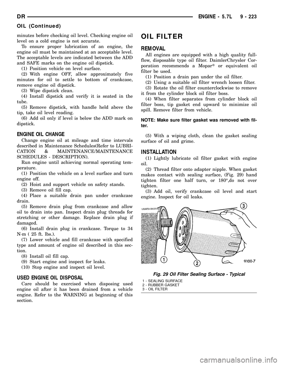
makes contact with sealing surface, (Fig. 29) hand
tighten filter one half turn, or 180É,do not over
tighten.
(3) Add oil, verify crankcase oil level and start
engine. Inspect for oil leaks.
Fig. 29 Oil Filter Sealing Surface - Typical
1 - SEALING SURFACE
2 - RUBBER GASKET
3 - OIL FILTER
DRENGINE - 5.7L 9 - 223
OIL (Continued)
Page 1462 of 2627
DIAGNOSIS AND TESTING - CYLINDER
COMPRESSION/LEAKAGE TESTS
CYLINDER COMPRESSION PRESSURE
The results of a cylinder compression pressure test
can be utilized to diagnose several engine malfunc-
tions.
Ensure batteries are completely charged and the
engine starter motor is in good operating condition.
Otherwise, the indicated compression pressures may
not be valid for diagnostic purposes.
(1) Disconnect the fuel inlet line to the fuel trans-
fer pump. Plug the fuel line from the fuel tank.
(2) Start the engine and idle until the engine stalls
(runs out of fuel).
(3) Disconnect all three injector wire harness con-
nectors at the rocker housing.
(4) Remove the breather cover and cylinder head
cover.
(5) Remove the high pressure fuel line between the
cylinder head and fuel rail for the cylinder to be
tested. Use tool# 9011 to cap this fuel rail on the cyl-
inder being tested.
(6) Remove the exhaust rocker lever.
(7) Use Tool 9010 to remove the injector and cop-
per sealing washer.
(8) Install the exhaust rocker lever and torque to
36 N´m (27 ft. lbs.).
(9) Cover the remaining rocker levers with clean
shop towels to prevent any oil splatter under the
hood.
(10) Place a rag over the compression test tool fit-
ting. Crank the engine for 2±3 seconds to purge any
fuel that may have drained into the cylinder when
the injector was removed.
(11) Connect the compression test gauge.
(12) Crank the engine for 5 seconds and record the
pressure reading. Repeat this step three times and
calculate the average of the three readings.
NOTE: The minimum cylinder pressure is 350 psi.
Cylinder pressure should be within 20% from cylin-
der to cylinder.
(13) Combustion pressure leakage can be checked
if cylinder pressure is below the specification. Per-
form the leakage test procedure on each cylinder
according to the tester manufacturer instructions.
(14) Upon completion of the test check an erase
any engine related fault codes.
CYLINDER COMBUSTION PRESSURE LEAKAGE
The combustion pressure leakage test provides an
accurate means for determining engine condition.
Combustion pressure leakage testing will detect:²Exhaust and intake valve leaks (improper seat-
ing).
²Leaks between adjacent cylinders or into water
jacket.
²Any causes for combustion/compression pressure
loss
(1) Start and operate the engine until it attains
normal operating temperature.
(2) Remove the breather cover and cylinder head
cover.
(3) Disconnect all three injector wire harness con-
nectors at the rocker housing.
(4) Bring the cylinder to be tested to TDC.
(5) Remove the high pressure fuel line between the
cylinder head and the fuel rail for the cylinder to be
tested.
(6) Install capping Tool 9011 onto the rail.
(7) Remove the high pressure connector nut and
high pressure connector with Tool 9015.
(8) Remove the exhaust and intake rocker lever.
(9) Use Tool 9010 to remove the injector and cop-
per sealing washer.
(10) Install compression test Tool 9007 into the
injector bore.
(11) Connect the leakage tester and perform the
leakage test procedure on each cylinder according to
the tester manufacturer's instructions.
(12) Upon completion of the test check and erase
any engine related fault codes.
STANDARD PROCEDURE
STANDARD PROCEDURE - FORM-IN-PLACE
GASKETS AND SEALERS
There are numerous places where form-in-place
gaskets are used on the engine. Care must be taken
when applying form-in-place gaskets to assure
obtaining the desired results.Do not use form-in-
place gasket material unless specified.Bead size,
continuity, and location are of great importance. Too
thin a bead can result in leakage while too much can
result in spill-over which can break off and obstruct
fluid feed lines. A continuous bead of the proper
width is essential to obtain a leak-free gasket.
There are numerous types of form-in-place gasket
materials that are used in the engine area. Mopart
Engine RTV GEN II, MopartATF-RTV, and Mopart
Gasket Maker gasket materials, each have different
properties and can not be used in place of the other.
MOPARtENGINE RTV GEN II
MopartEngine RTV GEN II is used to seal com-
ponents exposed to engine oil. This material is a spe-
cially designed black silicone rubber RTV that
retains adhesion and sealing properties when
exposed to engine oil. Moisture in the air causes the
DRENGINE 5.9L DIESEL 9 - 239
ENGINE 5.9L DIESEL (Continued)
Page 1467 of 2627
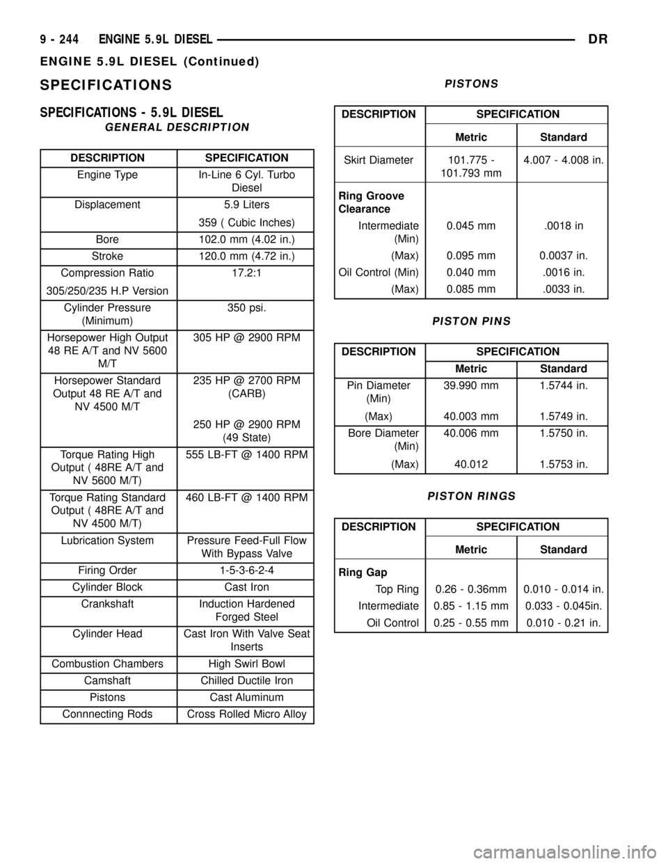
SPECIFICATIONS
SPECIFICATIONS - 5.9L DIESEL
GENERAL DESCRIPTION
DESCRIPTION SPECIFICATION
Engine Type In-Line 6 Cyl. Turbo
Diesel
Displacement 5.9 Liters
359 ( Cubic Inches)
Bore 102.0 mm (4.02 in.)
Stroke 120.0 mm (4.72 in.)
Compression Ratio 17.2:1
305/250/235 H.P Version
Cylinder Pressure
(Minimum)350 psi.
Horsepower High Output
48 RE A/T and NV 5600
M/T305 HP @ 2900 RPM
Horsepower Standard
Output 48 RE A/T and
NV 4500 M/T235 HP @ 2700 RPM
(CARB)
250 HP @ 2900 RPM
(49 State)
Torque Rating High
Output ( 48RE A/T and
NV 5600 M/T)555 LB-FT @ 1400 RPM
Torque Rating Standard
Output ( 48RE A/T and
NV 4500 M/T)460 LB-FT @ 1400 RPM
Lubrication System Pressure Feed-Full Flow
With Bypass Valve
Firing Order 1-5-3-6-2-4
Cylinder Block Cast Iron
Crankshaft Induction Hardened
Forged Steel
Cylinder Head Cast Iron With Valve Seat
Inserts
Combustion Chambers High Swirl Bowl
Camshaft Chilled Ductile Iron
Pistons Cast Aluminum
Connnecting Rods Cross Rolled Micro Alloy
PISTONS
DESCRIPTION SPECIFICATION
Metric Standard
Skirt Diameter 101.775 -
101.793 mm4.007 - 4.008 in.
Ring Groove
Clearance
Intermediate
(Min)0.045 mm .0018 in
(Max) 0.095 mm 0.0037 in.
Oil Control (Min) 0.040 mm .0016 in.
(Max) 0.085 mm .0033 in.
PISTON PINS
DESCRIPTION SPECIFICATION
Metric Standard
Pin Diameter
(Min)39.990 mm 1.5744 in.
(Max) 40.003 mm 1.5749 in.
Bore Diameter
(Min)40.006 mm 1.5750 in.
(Max) 40.012 1.5753 in.
PISTON RINGS
DESCRIPTION SPECIFICATION
Metric Standard
Ring Gap
Top Ring 0.26 - 0.36mm 0.010 - 0.014 in.
Intermediate 0.85 - 1.15 mm 0.033 - 0.045in.
Oil Control 0.25 - 0.55 mm 0.010 - 0.21 in.
9 - 244 ENGINE 5.9L DIESELDR
ENGINE 5.9L DIESEL (Continued)