1998 DODGE RAM 1500 Intake removal
[x] Cancel search: Intake removalPage 1493 of 2627
INSPECTION
Camshaft
(1) Inspect the valve lobes and bearing journals for
cracks, pitting, scoring, or generally excessive wear.
Replace any camshaft that exceeds the allowable lim-
its.
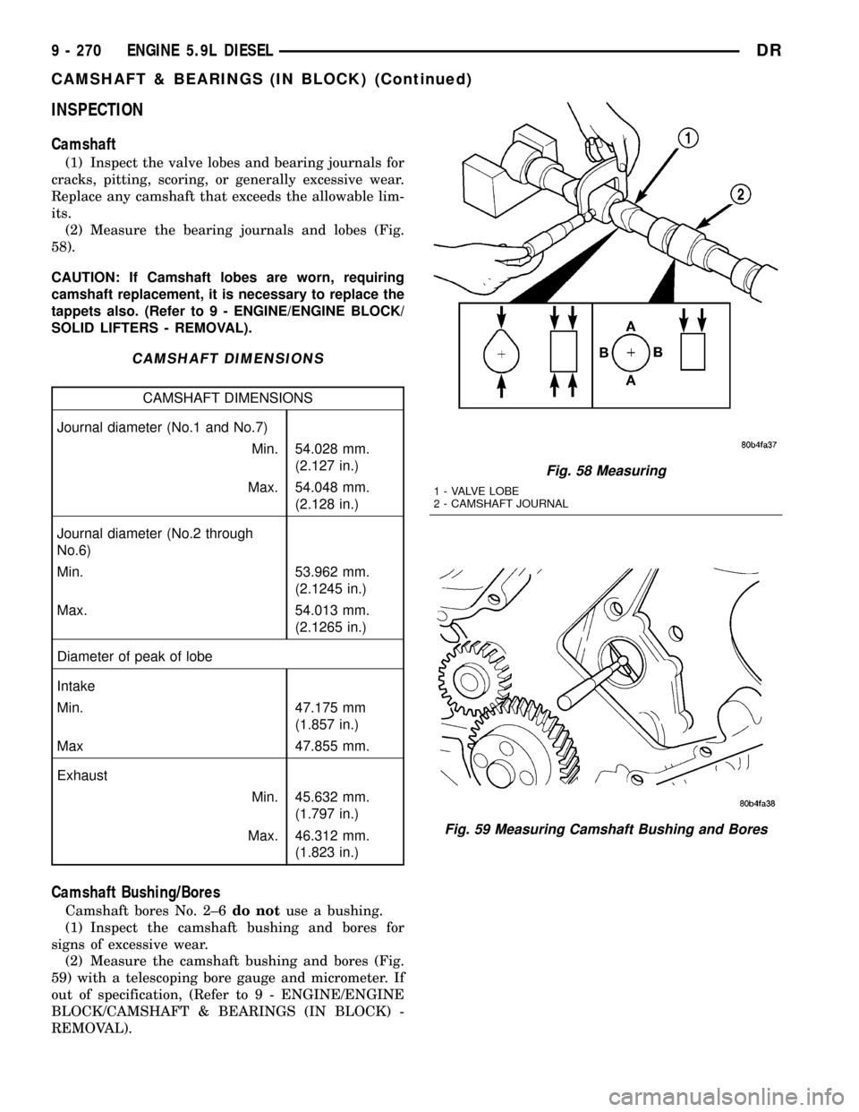
(2) Measure the bearing journals and lobes (Fig.
58).
CAUTION: If Camshaft lobes are worn, requiring
camshaft replacement, it is necessary to replace the
tappets also. (Refer to 9 - ENGINE/ENGINE BLOCK/
SOLID LIFTERS - REMOVAL).
CAMSHAFT DIMENSIONS
CAMSHAFT DIMENSIONS
Journal diameter (No.1 and No.7)
Min. 54.028 mm.
(2.127 in.)
Max. 54.048 mm.
(2.128 in.)
Journal diameter (No.2 through
No.6)
Min. 53.962 mm.
(2.1245 in.)
Max. 54.013 mm.
(2.1265 in.)
Diameter of peak of lobe
Intake
Min. 47.175 mm
(1.857 in.)
Max 47.855 mm.
Exhaust
Min. 45.632 mm.
(1.797 in.)
Max. 46.312 mm.
(1.823 in.)
Camshaft Bushing/Bores
Camshaft bores No. 2±6do notuse a bushing.
(1) Inspect the camshaft bushing and bores for
signs of excessive wear.
(2) Measure the camshaft bushing and bores (Fig.
59) with a telescoping bore gauge and micrometer. If
out of specification, (Refer to 9 - ENGINE/ENGINE
BLOCK/CAMSHAFT & BEARINGS (IN BLOCK) -
REMOVAL).
Fig. 59 Measuring Camshaft Bushing and Bores
Fig. 58 Measuring
1 - VALVE LOBE
2 - CAMSHAFT JOURNAL
9 - 270 ENGINE 5.9L DIESELDR
CAMSHAFT & BEARINGS (IN BLOCK) (Continued)
Page 1504 of 2627
PISTON & CONNECTING ROD
DESCRIPTION
PISTONS
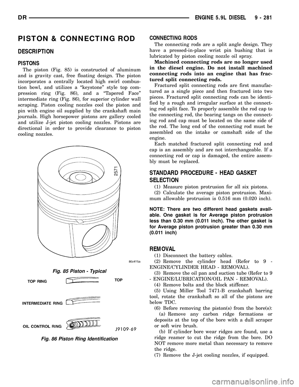
The piston (Fig. 85) is constructed of aluminum
and is gravity cast, free floating design. The piston
incorporates a centrally located high swirl combus-
tion bowl, and utilizes a ªkeystoneº style top com-
pression ring (Fig. 86), and a ªTapered Faceº
intermediate ring (Fig. 86), for superior cylinder wall
scraping. Piston cooling nozzles cool the piston and
pin with engine oil supplied by the crankshaft main
journals. High horsepower pistons are gallery cooled
and utilize J-jet piston cooling nozzles. Pistons are
directional in order to provide clearance to piston
cooling nozzles.
CONNECTING RODS
The connecting rods are a split angle design. They
have a pressed-in-place wrist pin bushing that is
lubricated by piston cooling nozzle oil spray.
Machined connecting rods are no longer used
in the diesel engine. Do not install machined
connecting rods into an engine that has frac-
tured split connecting rods.
Fractured split connecting rods are first manufac-
tured as a single piece and then fractured into two
pieces. Fractured split connecting rods can be identi-
fied by a rough and irregular surface at the connect-
ing rod split face. To properly assemble the rod cap to
the connecting rod, the bearing tangs on the connect-
ing rod and cap must be located on the same side of
the rod. The long end of the connecting rod must be
assembled on the intake or camshaft side of the
engine.
Each matched fractured split connecting rod and
cap is an assembly and are not interchangeable. If a
connecting rod or cap is damaged, the entire assem-
bly must be replaced.
STANDARD PROCEDURE - HEAD GASKET
SELECTION
(1) Measure piston protrusion for all six pistons.
(2) Calculate the average piston protrusion. Maxi-
mum allowable protrusion is 0.516 mm (0.020 inch).
NOTE: There are two different head gaskets avail-
able. One gasket is for Average piston protrusion
less than 0.30 mm (0.011 inch). The other gasket is
for Average piston protrusion greater than 0.30 mm
(0.011 inch)
REMOVAL
(1) Disconnect the battery cables.
(2) Remove the cylinder head (Refer to 9 -
ENGINE/CYLINDER HEAD - REMOVAL).
(3) Remove the oil pan and suction tube (Refer to 9
- ENGINE/LUBRICATION/OIL PAN - REMOVAL).
(4) Remove bolts and the block stiffener.
(5) Using Miller Tool 7471-B crankshaft barring
tool, rotate the crankshaft so all of the pistons are
below TDC.
(6) Before removing the piston(s) from the bore(s):
(a) Remove any carbon ridge formations or
deposits at the top of the bore with a dull scraper
or soft wire brush.
(b) If cylinder bore wear ridges are found, use a
ridge reamer to cut the ridge from the bore. DO
NOT remove more metal than necessary to remove
the ridge.
(7) Remove the J-jet cooling nozzles, if equipped.
Fig. 85 Piston - Typical
Fig. 86 Piston Ring Identification
DRENGINE 5.9L DIESEL 9 - 281
Page 1520 of 2627
(13) Install the cooling fan (Refer to 7 - COOLING/
ENGINE/RADIATOR FAN - INSTALLATION).
(14) Connect battery negative cables.
(15) Start engine and check for oil leaks.
INTAKE MANIFOLD
REMOVAL
(1) Disconnect the battery negative cables.
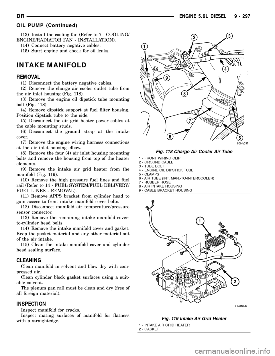
(2) Remove the charge air cooler outlet tube from
the air inlet housing (Fig. 118).
(3) Remove the engine oil dipstick tube mounting
bolt (Fig. 118).
(4) Remove dipstick support at fuel filter housing.
Position dipstick tube to the side.
(5) Disconnect the air grid heater power cables at
the cable mounting studs.
(6) Disconnect the ground strap at the intake
cover.
(7) Remove the engine wiring harness connections
at the air inlet housing elbow.
(8) Remove the four (4) air inlet housing mounting
bolts and remove the housing from top of the heater
elements.
(9) Remove the intake air grid heater from the
manifold (Fig. 119).
(10) Remove the high pressure fuel lines and fuel
rail (Refer to 14 - FUEL SYSTEM/FUEL DELIVERY/
FUEL LINES - REMOVAL).
(11) Remove APPS bracket from cylinder head to
gain access to front intake manifold cover bolts.
(12) Disconnect manifold air temperature/pressure
sensor connector.
(13) Remove the remaining intake manifold cover-
to-cylinder head bolts.
(14) Remove the intake manifold cover and gasket.
Keep the gasket material and any other material out
of the air intake.
(15) Clean the intake manifold cover and cylinder
head sealing surface.
CLEANING
Clean manifold in solvent and blow dry with com-
pressed air.
Clean cylinder block gasket surfaces using a suit-
able solvent.
The plenum pan rail must be clean and dry (free of
all foreign material).
INSPECTION
Inspect manifold for cracks.
Inspect mating surfaces of manifold for flatness
with a straightedge.
Fig. 118 Charge Air Cooler Air Tube
1 - FRONT WIRING CLIP
2 - GROUND CABLE
3 - TUBE BOLT
4 - ENGINE OIL DIPSTICK TUBE
5 - CLAMPS
6 - AIR TUBE (INT. MAN.-TO-INTERCOOLER)
7 - RUBBER HOSE
8 - AIR INTAKE HOUSING
9 - CABLE BRACKET HOUSING
Fig. 119 Intake Air Grid Heater
1 - INTAKE AIR GRID HEATER
2 - GASKET
DRENGINE 5.9L DIESEL 9 - 297
OIL PUMP (Continued)
Page 1521 of 2627
INSTALLATION
(1) Using a new gasket, install the intake manifold
cover.
(2) Install the cover-to-cylinder head bolts that do
not hold down the fuel rail. Tighten the bolts to 24
N´m (18 ft. lbs.) torque.
(3) Install the high pressure rail and fuel lines
(Refer to 14 - FUEL SYSTEM/FUEL DELIVERY/
FUEL LINES - INSTALLATION).
(4) Using two (2) new gaskets, install the intake
air grid heater and air inlet housing. Position the
ground cable and install and tighten the bolts to 24
N´m (18 ft. lbs.) torque.
(5) Connect the manifold air temperature/pressure
sensor connector.
(6) Install and tighten the air intake heater power
supply nuts to 14 N´m (120 in. lbs.) torque.
(7) Install the APPS bracket. Torque fasteners to
43 N´m (32ft lbs.) torque.
(8) Install oil dipstick tube support at fuel filter
housing.
(9) Install the engine oil dipstick tube and mount-
ing bolt.
(10) Position the charge air cooler outlet tube onto
the air inlet housing. Tighten the clamps to 11 N´m
(100 in. lbs.) torque.
(11) Attach the engine wire harness to the air inlet
housing at two locations.
(12) Prime the fuel system. Refer to the fuel prim-
ing procedure in Group 14, Fuel System.
(13) Connect the battery negative cables.
EXHAUST MANIFOLD
REMOVAL
(1) Disconnect the battery negative cables.
(2) Raise vehicle on hoist.
(3) Disconnect the exhaust pipe from the turbo-
charger elbow.
(4) Disconnect oil drain tube from turbocharger.
(5) Lower vehicle.
(6) Disconnect the turbocharger air inlet hose.
(7) Remove air cleaner assembly.
(8) Disconnect the turbocharger oil supply line.
(9) Disconnect the charge air cooler inlet pipe from
the turbocharger.
(10) Remove the turbocharger and gasket from the
exhaust manifold.
(11) Remove the cab heater return pipe nuts from
the exhaust manifold stud. Position the tube out of
the way.
(12) Remove heat shield.
(13) Remove exhaust manifold bolt lockplates.
(14) Remove the exhaust manifold-to-cylinder head
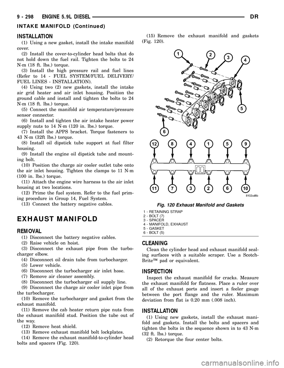
bolts and spacers (Fig. 120).(15) Remove the exhaust manifold and gaskets
(Fig. 120).
CLEANING
Clean the cylinder head and exhaust manifold seal-
ing surfaces with a suitable scraper. Use a Scotch-
BriteŸ pad or equivalent.
INSPECTION
Inspect the exhaust manifold for cracks. Measure
the exhaust manifold for flatness. Place a ruler over
all of the exhaust ports and insert a feeler gauge
between the port flange and the ruler. Maximum
deviation from flat is 0.20 mm (.008 inch).
INSTALLATION
(1) Using new gaskets, install the exhaust mani-
fold and gaskets. Install the bolts and spacers and
tighten the bolts in the sequence shown in to 43 N´m
(32 ft. lbs.) torque.
(2) Retorque the four center bolts.
Fig. 120 Exhaust Manifold and Gaskets
1 - RETAINING STRAP
2 - BOLT (7)
3 - SPACER
4 - MANIFOLD, EXHAUST
5 - GASKET
6 - BOLT (5)
9 - 298 ENGINE 5.9L DIESELDR
INTAKE MANIFOLD (Continued)
Page 1536 of 2627
INSTALLATION
(1) Install the tailpipe into the muffler.
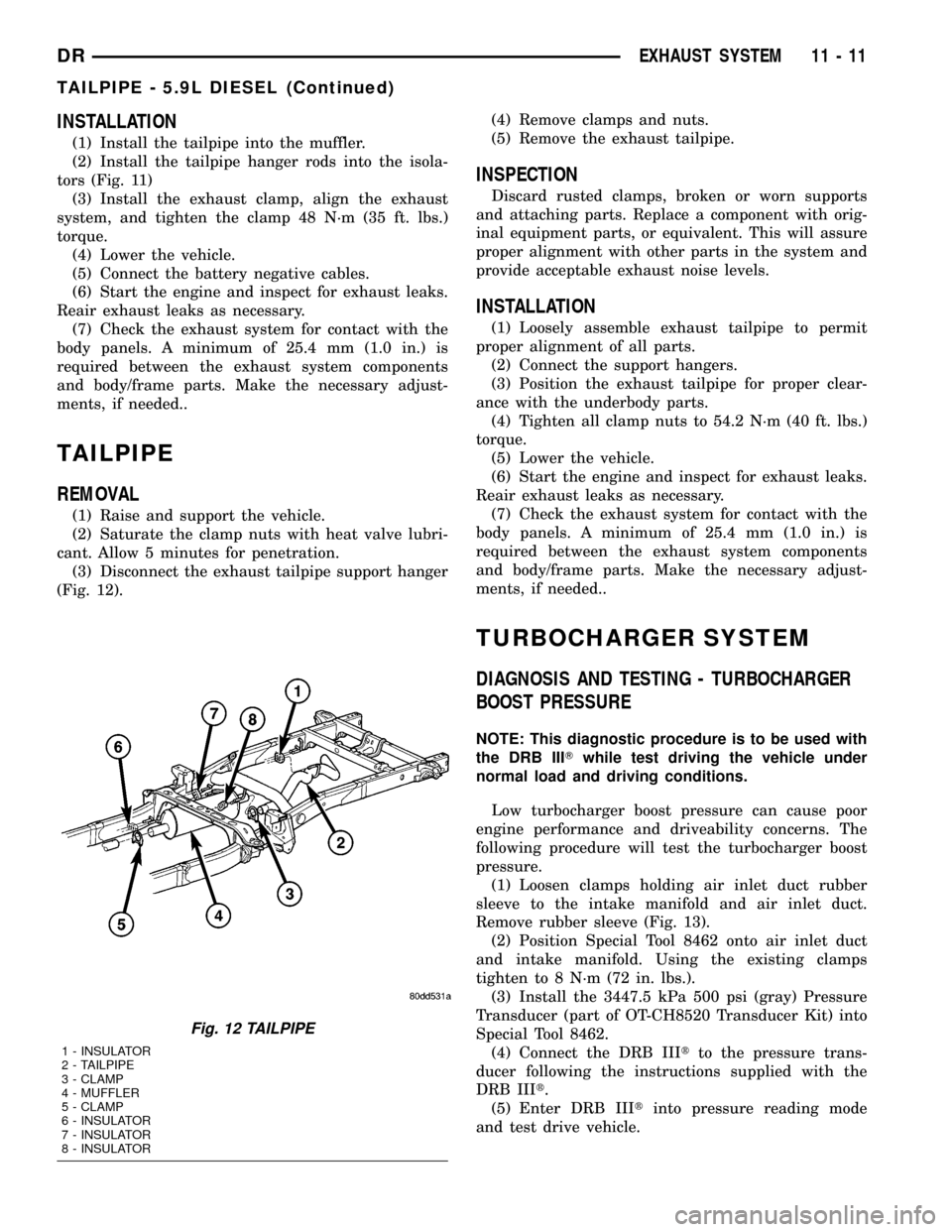
(2) Install the tailpipe hanger rods into the isola-
tors (Fig. 11)
(3) Install the exhaust clamp, align the exhaust
system, and tighten the clamp 48 N´m (35 ft. lbs.)
torque.
(4) Lower the vehicle.
(5) Connect the battery negative cables.
(6) Start the engine and inspect for exhaust leaks.
Reair exhaust leaks as necessary.
(7) Check the exhaust system for contact with the
body panels. A minimum of 25.4 mm (1.0 in.) is
required between the exhaust system components
and body/frame parts. Make the necessary adjust-
ments, if needed..
TAILPIPE
REMOVAL
(1) Raise and support the vehicle.
(2) Saturate the clamp nuts with heat valve lubri-
cant. Allow 5 minutes for penetration.
(3) Disconnect the exhaust tailpipe support hanger
(Fig. 12).(4) Remove clamps and nuts.
(5) Remove the exhaust tailpipe.
INSPECTION
Discard rusted clamps, broken or worn supports
and attaching parts. Replace a component with orig-
inal equipment parts, or equivalent. This will assure
proper alignment with other parts in the system and
provide acceptable exhaust noise levels.
INSTALLATION
(1) Loosely assemble exhaust tailpipe to permit
proper alignment of all parts.
(2) Connect the support hangers.
(3) Position the exhaust tailpipe for proper clear-
ance with the underbody parts.
(4) Tighten all clamp nuts to 54.2 N´m (40 ft. lbs.)
torque.
(5) Lower the vehicle.
(6) Start the engine and inspect for exhaust leaks.
Reair exhaust leaks as necessary.
(7) Check the exhaust system for contact with the
body panels. A minimum of 25.4 mm (1.0 in.) is
required between the exhaust system components
and body/frame parts. Make the necessary adjust-
ments, if needed..
TURBOCHARGER SYSTEM
DIAGNOSIS AND TESTING - TURBOCHARGER
BOOST PRESSURE
NOTE: This diagnostic procedure is to be used with
the DRB IIITwhile test driving the vehicle under
normal load and driving conditions.
Low turbocharger boost pressure can cause poor
engine performance and driveability concerns. The
following procedure will test the turbocharger boost
pressure.
(1) Loosen clamps holding air inlet duct rubber
sleeve to the intake manifold and air inlet duct.
Remove rubber sleeve (Fig. 13).
(2) Position Special Tool 8462 onto air inlet duct
and intake manifold. Using the existing clamps
tighten to 8 N´m (72 in. lbs.).
(3) Install the 3447.5 kPa 500 psi (gray) Pressure
Transducer (part of OT-CH8520 Transducer Kit) into
Special Tool 8462.
(4) Connect the DRB IIItto the pressure trans-
ducer following the instructions supplied with the
DRB IIIt.
(5) Enter DRB IIItinto pressure reading mode
and test drive vehicle.
Fig. 12 TAILPIPE
1 - INSULATOR
2 - TAILPIPE
3 - CLAMP
4 - MUFFLER
5 - CLAMP
6 - INSULATOR
7 - INSULATOR
8 - INSULATOR
DREXHAUST SYSTEM 11 - 11
TAILPIPE - 5.9L DIESEL (Continued)
Page 1542 of 2627
CAUTION: Do not apply more than 138 kPa (20 psi)
air pressure to the charge air cooler system, sever
damage to the charge air cooler system may occur.
(3) Connect a regulated air supply to air fitting on
Tool 9022 Adapter. Set air pressure to a Maximum of
138 kPa (20 psi).
(4) Using soapy water check the rubber sleeves,
charge air cooler and intake manifold for leaks.
REMOVAL
WARNING: IF THE ENGINE WAS JUST TURNED
OFF, THE AIR INTAKE SYSTEM TUBES MAY BE
HOT.
(1) Disconnect the battery negative cables.
(2) Discharge the A/C system (Refer to 24 - HEAT-
ING & AIR CONDITIONING/PLUMBING - STAN-
DARD PROCEDURE) and remove the A/C condenser
(Refer to 24 - HEATING & AIR CONDITIONING/
PLUMBING/A/C CONDENSER - REMOVAL) (if A/C
equipped).
(3) Remove the transmission auxiliary cooler
(Refer to 7 - COOLING/TRANSMISSION/TRANS
COOLER - REMOVAL).
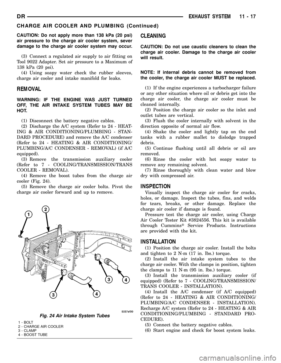
(4) Remove the boost tubes from the charge air
cooler (Fig. 24).
(5) Remove the charge air cooler bolts. Pivot the
charge air cooler forward and up to remove.
CLEANING
CAUTION: Do not use caustic cleaners to clean the
charge air cooler. Damage to the charge air cooler
will result.
NOTE: If internal debris cannot be removed from
the cooler, the charge air cooler MUST be replaced.
(1) If the engine experiences a turbocharger failure
or any other situation where oil or debris get into the
charge air cooler, the charge air cooler must be
cleaned internally.
(2) Position the charge air cooler so the inlet and
outlet tubes are vertical.
(3) Flush the cooler internally with solvent in the
direction opposite of normal air flow.
(4) Shake the cooler and lightly tap on the end
tanks with a rubber mallet to dislodge trapped
debris.
(5) Continue flushing until all debris or oil are
removed.
(6) Rinse the cooler with hot soapy water to
remove any remaining solvent.
(7) Rinse thoroughly with clean water and blow
dry with compressed air.
INSPECTION
Visually inspect the charge air cooler for cracks,
holes, or damage. Inspect the tubes, fins, and welds
for tears, breaks, or other damage. Replace the
charge air cooler if damage is found.
Pressure test the charge air cooler, using Charge
Air Cooler Tester Kit #3824556. This kit is available
through CumminstService Products. Instructions
are provided with the kit.
INSTALLATION
(1) Position the charge air cooler. Install the bolts
and tighten to 2 N´m (17 in. lbs.) torque.
(2) Install the air intake system tubes to the
charge air cooler. With the clamps in position, tighten
the clamps to 11 N´m (95 in. lbs.) torque.
(3) Install the transmission auxiliary cooler (if
equipped) (Refer to 7 - COOLING/TRANSMISSION/
TRANS COOLER - INSTALLATION).
(4) Install the A/C condenser (if A/C equipped)
(Refer to 24 - HEATING & AIR CONDITIONING/
PLUMBING/A/C CONDENSER - INSTALLATION).
Recharge A/C system (Refer to 24 - HEATING & AIR
CONDITIONING/PLUMBING - STANDARD PRO-
CEDURE).
(5) Connect the battery negative cables.
(6) Start engine and check for boost system leaks.
Fig. 24 Air Intake System Tubes
1 - BOLT
2 - CHARGE AIR COOLER
3 - CLAMP
4 - BOOST TUBE
DREXHAUST SYSTEM 11 - 17
CHARGE AIR COOLER AND PLUMBING (Continued)
Page 1554 of 2627
STANDARD PROCEDURE - HYDROFORM
FENDER RAIL REPAIR
CAUTION: This repair procedure assumes damage
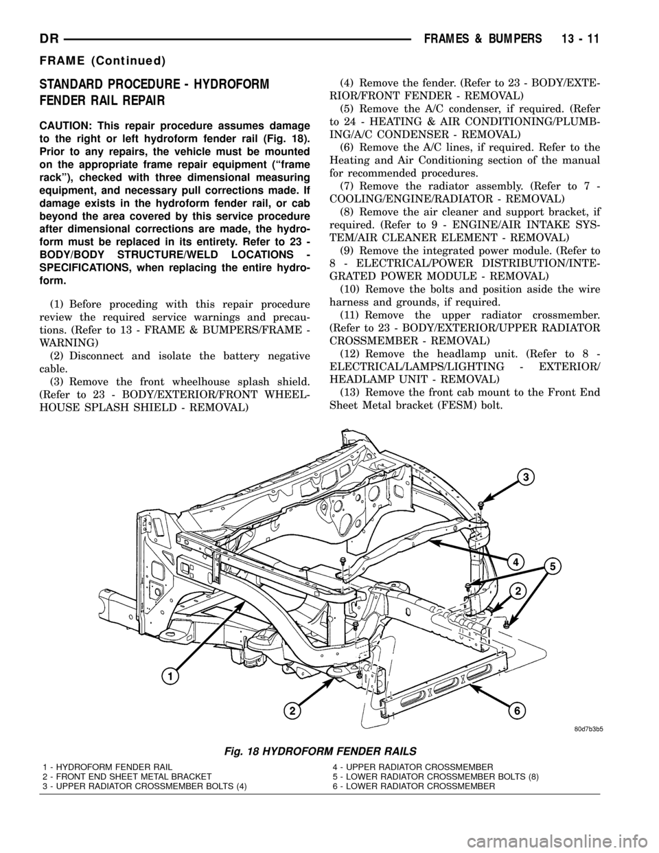
to the right or left hydroform fender rail (Fig. 18).
Prior to any repairs, the vehicle must be mounted
on the appropriate frame repair equipment (ªframe
rackº), checked with three dimensional measuring
equipment, and necessary pull corrections made. If
damage exists in the hydroform fender rail, or cab
beyond the area covered by this service procedure
after dimensional corrections are made, the hydro-
form must be replaced in its entirety. Refer to 23 -
BODY/BODY STRUCTURE/WELD LOCATIONS -
SPECIFICATIONS, when replacing the entire hydro-
form.
(1) Before proceding with this repair procedure
review the required service warnings and precau-
tions. (Refer to 13 - FRAME & BUMPERS/FRAME -
WARNING)
(2) Disconnect and isolate the battery negative
cable.
(3) Remove the front wheelhouse splash shield.
(Refer to 23 - BODY/EXTERIOR/FRONT WHEEL-
HOUSE SPLASH SHIELD - REMOVAL)(4) Remove the fender. (Refer to 23 - BODY/EXTE-
RIOR/FRONT FENDER - REMOVAL)
(5) Remove the A/C condenser, if required. (Refer
to 24 - HEATING & AIR CONDITIONING/PLUMB-
ING/A/C CONDENSER - REMOVAL)
(6) Remove the A/C lines, if required. Refer to the
Heating and Air Conditioning section of the manual
for recommended procedures.
(7) Remove the radiator assembly. (Refer to 7 -
COOLING/ENGINE/RADIATOR - REMOVAL)
(8) Remove the air cleaner and support bracket, if
required. (Refer to 9 - ENGINE/AIR INTAKE SYS-
TEM/AIR CLEANER ELEMENT - REMOVAL)
(9) Remove the integrated power module. (Refer to
8 - ELECTRICAL/POWER DISTRIBUTION/INTE-
GRATED POWER MODULE - REMOVAL)
(10) Remove the bolts and position aside the wire
harness and grounds, if required.
(11) Remove the upper radiator crossmember.
(Refer to 23 - BODY/EXTERIOR/UPPER RADIATOR
CROSSMEMBER - REMOVAL)
(12) Remove the headlamp unit. (Refer to 8 -
ELECTRICAL/LAMPS/LIGHTING - EXTERIOR/
HEADLAMP UNIT - REMOVAL)
(13) Remove the front cab mount to the Front End
Sheet Metal bracket (FESM) bolt.
Fig. 18 HYDROFORM FENDER RAILS
1 - HYDROFORM FENDER RAIL
2 - FRONT END SHEET METAL BRACKET
3 - UPPER RADIATOR CROSSMEMBER BOLTS (4)4 - UPPER RADIATOR CROSSMEMBER
5 - LOWER RADIATOR CROSSMEMBER BOLTS (8)
6 - LOWER RADIATOR CROSSMEMBER
DRFRAMES & BUMPERS 13 - 11
FRAME (Continued)
Page 1584 of 2627
(2) Perform Fuel System Pressure Release Proce-
dure.
(3) Remove negative battery cable at battery.
(4) Remove flex tube (air cleaner housing to
engine).
(5) Remove air resonator box at throttle body.
(6) Disconnect all spark plug cables from all spark
plugs and ignition coils. Do not remove cables from
cable routing tray. Note original cable positions while
removing (Fig. 22).
(7) Remove spark plug cable tray from engine by
releasing 4 retaining clips (Fig. 21). Remove tray and
cables from engine as an assembly.
(8) Disconnect electrical connectors at all 8 igni-
tion coils. Refer to Ignition Coil Removal/Installation.
(9) Disconnect fuel line latch clip and fuel line at
fuel rail. A special tool will be necessary for fuel line
disconnection. Refer to Quick-Connect Fittings.
(10) Disconnect electrical connectors at all 8 fuel
injectors. To remove connector refer to (Fig. 17). Push
red colored slider away from injector (1). While push-
ing slider, depress tab (2) and remove connector (3)
from injector. The factory fuel injection wiring har-
ness is numerically tagged (INJ 1, INJ 2, etc.) for
injector position identification. If harness is not
tagged, note wiring location before removal.
(11) Disconnect electrical connectors at all throttle
body sensors.
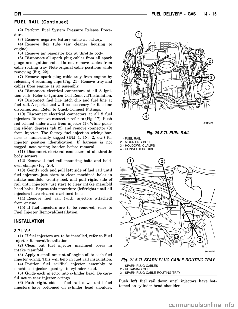
(12) Remove 4 fuel rail mounting bolts and hold-
own clamps (Fig. 20).
(13) Gently rock and pullleftside of fuel rail until
fuel injectors just start to clear machined holes in
intake manifold. Gently rock and pullrightside of
rail until injectors just start to clear intake manifold
head holes. Repeat this procedure (left/right) until all
injectors have cleared machined holes.
(14) Remove fuel rail (with injectors attached)
from engine.
(15) If fuel injectors are to be removed, refer to
Fuel Injector Removal/Installation.
INSTALLATION
3.7L V-6
(1) If fuel injectors are to be installed, refer to Fuel
Injector Removal/Installation.
(2) Clean out fuel injector machined bores in
intake manifold.
(3) Apply a small amount of engine oil to each fuel
injector o-ring. This will help in fuel rail installation.
(4) Position fuel rail/fuel injector assembly to
machined injector openings in cylinder head.
(5) Guide each injector into cylinder head. Be care-
ful not to tear injector o-rings.
(6) Pushrightside of fuel rail down until fuel
injectors have bottomed on cylinder head shoulder.Pushleftfuel rail down until injectors have bot-
tomed on cylinder head shoulder.
Fig. 20 5.7L FUEL RAIL
1 - FUEL RAIL
2 - MOUNTING BOLT
3 - HOLDOWN CLAMPS
4 - CONNECTOR TUBE
Fig. 21 5.7L SPARK PLUG CABLE ROUTING TRAY
1 - SPARK PLUG CABLES
2 - RETAINING CLIP
3 - SPARK PLUG CABLE ROUTING TRAY
DRFUEL DELIVERY - GAS 14 - 15
FUEL RAIL (Continued)