1998 DODGE RAM 1500 Intake removal
[x] Cancel search: Intake removalPage 1604 of 2627
(4) Install MAP sensor mounting bolts (screws).
Refer to Torque Specifications.
(5) Connect electrical connector.
5.7L V-8
The Manifold Absolute Pressure (MAP) sensor is
mounted to the front of the intake manifold air ple-
num box (Fig. 24).
(1) Clean MAP sensor mounting hole at intake
manifold.
(2) Check MAP sensor o-ring seal for cuts or tears.
(3) Position sensor into manifold.
(4) Rotate sensor 1/4 turn clockwise for installa-
tion.
(5) Connect electrical connector.
OXYGEN SENSOR
DESCRIPTION
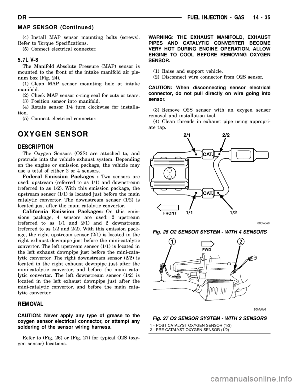
The Oxygen Sensors (O2S) are attached to, and
protrude into the vehicle exhaust system. Depending
on the engine or emission package, the vehicle may
use a total of either 2 or 4 sensors.
Federal Emission Packages :Two sensors are
used: upstream (referred to as 1/1) and downstream
(referred to as 1/2). With this emission package, the
upstream sensor (1/1) is located just before the main
catalytic convertor. The downstream sensor (1/2) is
located just after the main catalytic convertor.
California Emission Packages:On this emis-
sions package, 4 sensors are used: 2 upstream
(referred to as 1/1 and 2/1) and 2 downstream
(referred to as 1/2 and 2/2). With this emission pack-
age, the right upstream sensor (2/1) is located in the
right exhaust downpipe just before the mini-catalytic
convertor. The left upstream sensor (1/1) is located in
the left exhaust downpipe just before the mini-cata-
lytic convertor. The right downstream sensor (2/2) is
located in the right exhaust downpipe just after the
mini-catalytic convertor, and before the main cata-
lytic convertor. The left downstream sensor (1/2) is
located in the left exhaust downpipe just after the
mini-catalytic convertor, and before the main cata-
lytic convertor.
REMOVAL
CAUTION: Never apply any type of grease to the
oxygen sensor electrical connector, or attempt any
soldering of the sensor wiring harness.
Refer to (Fig. 26) or (Fig. 27) for typical O2S (oxy-
gen sensor) locations.WARNING: THE EXHAUST MANIFOLD, EXHAUST
PIPES AND CATALYTIC CONVERTER BECOME
VERY HOT DURING ENGINE OPERATION. ALLOW
ENGINE TO COOL BEFORE REMOVING OXYGEN
SENSOR.
(1) Raise and support vehicle.
(2) Disconnect wire connector from O2S sensor.
CAUTION: When disconnecting sensor electrical
connector, do not pull directly on wire going into
sensor.
(3) Remove O2S sensor with an oxygen sensor
removal and installation tool.
(4) Clean threads in exhaust pipe using appropri-
ate tap.
Fig. 26 O2 SENSOR SYSTEM - WITH 4 SENSORS
Fig. 27 O2 SENSOR SYSTEM - WITH 2 SENSORS
1 - POST CATALYST OXYGEN SENSOR (1/3)
2 - PRE-CATALYST OXYGEN SENSOR (1/2)
DRFUEL INJECTION - GAS 14 - 35
MAP SENSOR (Continued)
Page 1605 of 2627

INSTALLATION
Threads of new oxygen sensors are factory coated
with anti-seize compound to aid in removal.DO
NOT add any additional anti-seize compound to
threads of a new oxygen sensor.
(1) Install O2S sensor. Tighten to 30 N´m (22 ft.
lbs.) torque.
(2) Connect O2S sensor wire connector.
(3) Lower vehicle.
PTO SWITCH
DESCRIPTION
This Powertrain Control Module (PCM) input is
used only on models equipped with aftermarket
Power Take Off (PTO) units.
OPERATION
The input is used only to tell the PCM (or ECM-
Diesel) that the PTO has been engaged. The PCM (or
ECM) will disable (temporarily shut down) certain
OBD II diagnostic trouble codes when the PTO is
engaged.
JTEC and NGC Engine Controllers:When the
aftermarket PTO switch has been engaged, a 12V +
signal is sent through circuit G113 to PCM pin A13.
The PCM will then sense and determine that the
PTO has been activated.
CM 845 or CM 848 Diesel Engine Controllers:
When the aftermarket PTO switch has been engaged,
a 12V + signal is sent through circuit G113 to ECM
pin B38. The ECM will then sense and determine
that the PTO has been activated.
THROTTLE BODY
DESCRIPTION
The throttle body is located on the intake manifold.
Fuel does not enter the intake manifold through the
throttle body. Fuel is sprayed into the manifold by
the fuel injectors.
OPERATION
Filtered air from the air cleaner enters the intake
manifold through the throttle body. The throttle body
contains an air control passage controlled by an Idle
Air Control (IAC) motor. The air control passage is
used to supply air for idle conditions. A throttle valve
(plate) is used to supply air for above idle conditions.
5.7L V-8 Engine:
The throttle body on the 5.7L engine is an electri-
cally controlled unit. A mechanical cable is not used
to connect the throttle body to the accelerator pedal.
The Accelerator Pedal Position Sensor (APPS) alongwith inputs from other sensors sets the throttle blade
to pre-determined positions.
Except 5.7L V-8 Engine:
Certain sensors are attached to the throttle body.
The accelerator pedal cable, speed control cable and
transmission control cable (when equipped) are con-
nected to the throttle body linkage arm.
A (factory adjusted) set screw is used to mechani-
cally limit the position of the throttle body throttle
plate.Never attempt to adjust the engine idle
speed using this screw.All idle speed functions are
controlled by the PCM.
REMOVAL
3.7L V-6
A (factory adjusted) set screw is used to mechani-
cally limit the position of the throttle body throttle
plate.Never attempt to adjust the engine idle
speed using this screw.All idle speed functions are
controlled by the Powertrain Control Module (PCM).
(1) Remove air cleaner tube at throttle body.
(2) Disconnect throttle body electrical connectors
at IAC motor and TPS.
(3) Remove all control cables from throttle body
(lever) arm. Refer to the Accelerator Pedal and Throt-
tle Cable section for removal/installation procedures.
(4) Disconnect necessary vacuum lines at throttle
body.
(5) Remove 3 throttle body mounting bolts (Fig.
28).
(6) Remove throttle body from intake manifold.
(7) Check condition of old throttle body-to-intake
manifold o-ring (Fig. 29).
4.7L V-8
(1) Remove air duct and air resonator box at throt-
tle body.
(2) Disconnect throttle body electrical connectors
at IAC motor and TPS (Fig. 30).
(3) Remove vacuum line at throttle body.
(4) Remove all control cables from throttle body
(lever) arm. Refer to Accelerator Pedal and Throttle
Cable.
(5) Remove three throttle body mounting bolts
(Fig. 30).
(6) Remove throttle body from intake manifold.
5.7L V-8
CAUTION: Do not use spray (carb) cleaners on any
part of the throttle body. Do not apply silicone lubri-
cants to any part of the throttle body.
(1) Remove air duct and air resonator box at throt-
tle body.
14 - 36 FUEL INJECTION - GASDR
OXYGEN SENSOR (Continued)
Page 1607 of 2627

4.7L V-8
(1) Clean throttle body-to-intake manifold o-ring.(2) Clean mating surfaces of throttle body and
intake manifold.
(3) Install throttle body to intake manifold by posi-
tioning throttle body to manifold alignment pins.
(4) Install three mounting bolts. Tighten bolts to
12 N´m (105 in. lbs.) torque.
(5) Install control cables.
(6) Install vacuum line to throttle body.
(7) Install electrical connectors.
(8) Install air plenum.
5.7L V-8
CAUTION: Do not use spray (carb) cleaners on any
part of the throttle body. Do not apply silicone lubri-
cants to any part of the throttle body.
(1) Clean and check condition of throttle body-to-
intake manifold o-ring.
(2) Clean mating surfaces of throttle body and
intake manifold.
(3) Install throttle body to intake manifold by posi-
tioning throttle body to manifold alignment pins.
(4) Install 4 mounting bolts. Refer to Torque Spec-
ifications.
(5) Install electrical connector.
(6) Install air plenum.
(7)If the throttle body has been changed, the
following procedure must be performed:
(a) Disconnect negative battery cable from bat-
tery. Leave cable disconnected for approximately 90
seconds.
(b) Reconnect cable to battery.
(c) Turn ignition switch ON, but do not crank
engine.
(d) Leave ignition switch ON for a minimum of
10 seconds. This will allow PCM to learn throttle
body electrical parameters.
THROTTLE CONTROL CABLE
REMOVAL
3.7L V-6
CAUTION: Be careful not to damage or kink cable
core wire (within cable sheathing) while servicing
accelerator pedal or throttle cable.
(1) From inside vehicle, hold up accelerator pedal.
Remove plastic cable retainer (clip) and throttle cable
core wire from upper end of pedal arm (Fig. 1). Plas-
tic cable retainer snaps into top of pedal arm.
(2) Remove cable core wire at pedal arm.
(3) From inside vehicle, remove metal clip holding
cable to dashpanel (Fig. 1).
Fig. 31 5.7L V-8 THROTTLE BODY
1 - THROTTLE BODY
2 - ELECTRICAL CONNECTOR
3 - SILICONE SEAL
4 - MOUNTING BOLTS (4)
Fig. 32 5.7L V-8 THROTTLE BODY O-RING
1 - INTAKE MANIFOLD
2 - THROTTLE BODY O-RING
14 - 38 FUEL INJECTION - GASDR
THROTTLE BODY (Continued)
Page 1623 of 2627

REMOVAL
CAUTION: Cleanliness cannot be overemphasized
when handling or replacing diesel fuel system com-
ponents. This especially includes the fuel injectors,
high-pressure fuel lines and fuel injection pump.
Very tight tolerances are used with these parts. Dirt
contamination could cause rapid part wear and pos-
sible plugging of fuel injector nozzle tip holes. This
in turn could lead to possible engine misfire.
Always wash/clean any fuel system component
thoroughly before disassembly and then air dry.
Cap or cover any open part after disassembly.
Before assembly, examine each part for dirt, grease
or other contaminants and clean if necessary. When
installing new parts, lubricate them with clean
engine oil or clean diesel fuel only.
(1) Disconnect both negative battery cables at both
batteries. Cover and isolate ends of both cables.
(2) Remove intake manifold air intake tube (above
injection pump) and its rubber connector hose (Fig.
7).
(3) Remove accessory drive belt.
(4) Thoroughly clean the rear of injection pump,
and attachment points for its 3 fuel lines (Fig. 8).
Also clean the opposite ends of these same 3 lines at
their attachment points.
(5) Disconnect Fuel Control Actuator (FCA) electri-
cal connector at rear of injection pump (Fig. 9).
CAUTION: Whenever a fuel line fitting is connected
to a secondary fitting, always use a back-up wrench
on the secondary fitting. Do not allow the second-
ary fitting to rotate.
(6) Remove fuel line (injection pump-to-fuel pres-
sure limiting valve).
(7) Remove fuel line (injection pump-to-fuel rail).
Use back-up wrench on fitting at fuel pump.
(8) Remove fuel line (injection pump-to-fuel filter
housing).
(9) Remove fuel pump drive gear access cover
(plate) with a 3/8º drive ratchet. Plate is threaded to
timing gear cover (Fig. 10).
(10) Remove fuel pump drive gear mounting nut
and washer.
(11) Attach C3428B, or L4407A (or equivalent)
gear puller (Fig. 11) to pump drive gear with 2 bolts,
and separate gear from pump (a keyway is not used
on this particular injection pump). Leave drive gear
hanging loose within timing gear cover.
(12) Remove 3 injection pump mounting nuts (Fig.
12), and remove pump from engine.
Fig. 7 INTAKE TUBE AND CONNECTING HOSE
1 - MANIFOLD ABOVE HEATERS
2 - RUBBER CONNECTING HOSE
3 - METAL INTAKE TUBE
4 - CLAMPS (2)
Fig. 8 OVERFLOW VALVE
1 - BANJO BOLTS
2 - PUMP MOUNTING NUTS (3)
3 - FUEL INJECTION PUMP
4 - CASCADE OVERFLOW VALVE
14 - 54 FUEL DELIVERY - DIESELDR
FUEL INJECTION PUMP (Continued)
Page 1625 of 2627
This will ensure proper gear-to-shaft tighten-
ing.
(5) Clean pump gear and pump shaft at machined
tapers with an evaporative type cleaner such as
brake cleaner.
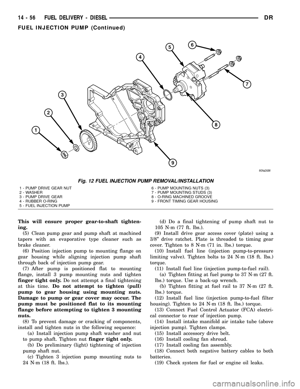
(6) Position injection pump to mounting flange on
gear housing while aligning injection pump shaft
through back of injection pump gear.
(7) After pump is positioned flat to mounting
flange, install 3 pump mounting nuts and tighten
finger tight only.Do not attempt a final tightening
at this time.Do not attempt to tighten (pull)
pump to gear housing using mounting nuts.
Damage to pump or gear cover may occur. The
pump must be positioned flat to its mounting
flange before attempting to tighten 3 mounting
nuts.
(8) To prevent damage or cracking of components,
install and tighten nuts in the following sequence:
(a) Install injection pump shaft washer and nut
to pump shaft. Tighten nutfinger tight only.
(b) Do preliminary (light) tightening of injection
pump shaft nut.
(c) Tighten 3 injection pump mounting nuts to
24 N´m (18 ft. lbs.).(d) Do a final tightening of pump shaft nut to
105 N´m (77 ft. lbs.).
(9) Install drive gear access cover (plate) using a
3/8º drive ratchet. Plate is threaded to timing gear
cover. Tighten to 8 N´m (71 in. lbs.) torque.
(10) Install fuel line (injection pump-to-pressure
limiting valve). Tighten bolts to 24 N´m (18 ft. lbs.)
torque.
(11) Install fuel line (injection pump-to-fuel rail).
(a) Tighten fitting at fuel pump to 37 N´m (27 ft.
lbs.) torque. Use a back-up wrench.
(b) Tighten fitting at fuel rail to 37 N´m (27 ft.
lbs.) torque.
(12) Install fuel line (injection pump-to-fuel filter
housing). Tighten to 24 N´m (18 ft. lbs.) torque.
(13) Connect Fuel Control Actuator (FCA) electri-
cal connector to rear of injection pump.
(14) Install intake manifold air intake tube (above
injection pump). Tighten clamps.
(15) Install accessory drive belt.
(16) Install cooling fan shroud.
(17) Install cooling fan assembly.
(18) Connect both negative battery cables to both
batteries.
(19) Check system for fuel or engine oil leaks.
Fig. 12 FUEL INJECTION PUMP REMOVAL/INSTALLATION
1 - PUMP DRIVE GEAR NUT
2 - WASHER
3 - PUMP DRIVE GEAR
4 - RUBBER O-RING
5 - FUEL INJECTION PUMP6 - PUMP MOUNTING NUTS (3)
7 - PUMP MOUNTING STUDS (3)
8 - O-RING MACHINED GROOVE
9 - FRONT TIMING GEAR HOUSING
14 - 56 FUEL DELIVERY - DIESELDR
FUEL INJECTION PUMP (Continued)
Page 1627 of 2627
WARNING: USE EXTREME CAUTION WHEN
INSPECTING FOR HIGH-PRESSURE FUEL LEAKS.
INSPECT FOR HIGH-PRESSURE FUEL LEAKS WITH
A SHEET OF CARDBOARD. HIGH FUEL INJECTION
PRESSURE CAN CAUSE PERSONAL INJURY IF
CONTACT IS MADE WITH THE SKIN.
DIAGNOSIS AND TESTING - HIGH-PRESSURE
FUEL LINE LEAKS
High-pressure fuel line leaks can cause starting
problems and poor engine performance.
WARNING: DUE TO EXTREME FUEL PRESSURES
OF UP TO 160,000 kPa (23,206 PSI), USE EXTREME
CAUTION WHEN INSPECTING FOR HIGH-PRES-
SURE FUEL LEAKS. DO NOT GET YOUR HAND OR
A FINGER NEAR A SUSPECTED LEAK. INSPECT
FOR HIGH-PRESSURE FUEL LEAKS WITH A SHEET
OF CARDBOARD. HIGH FUEL INJECTION PRES-
SURE CAN CAUSE PERSONAL INJURY IF CON-
TACT IS MADE WITH THE SKIN.
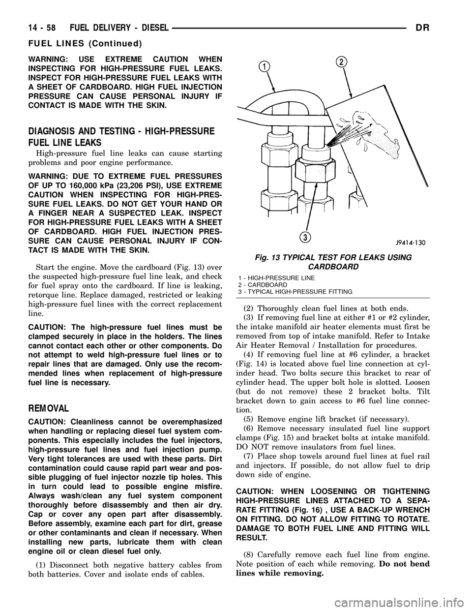
Start the engine. Move the cardboard (Fig. 13) over
the suspected high-pressure fuel line leak, and check
for fuel spray onto the cardboard. If line is leaking,
retorque line. Replace damaged, restricted or leaking
high-pressure fuel lines with the correct replacement
line.
CAUTION: The high-pressure fuel lines must be
clamped securely in place in the holders. The lines
cannot contact each other or other components. Do
not attempt to weld high-pressure fuel lines or to
repair lines that are damaged. Only use the recom-
mended lines when replacement of high-pressure
fuel line is necessary.
REMOVAL
CAUTION: Cleanliness cannot be overemphasized
when handling or replacing diesel fuel system com-
ponents. This especially includes the fuel injectors,
high-pressure fuel lines and fuel injection pump.
Very tight tolerances are used with these parts. Dirt
contamination could cause rapid part wear and pos-
sible plugging of fuel injector nozzle tip holes. This
in turn could lead to possible engine misfire.
Always wash/clean any fuel system component
thoroughly before disassembly and then air dry.
Cap or cover any open part after disassembly.
Before assembly, examine each part for dirt, grease
or other contaminants and clean if necessary. When
installing new parts, lubricate them with clean
engine oil or clean diesel fuel only.
(1) Disconnect both negative battery cables from
both batteries. Cover and isolate ends of cables.(2) Thoroughly clean fuel lines at both ends.
(3) If removing fuel line at either #1 or #2 cylinder,
the intake manifold air heater elements must first be
removed from top of intake manifold. Refer to Intake
Air Heater Removal / Installation for procedures.
(4) If removing fuel line at #6 cylinder, a bracket
(Fig. 14) is located above fuel line connection at cyl-
inder head. Two bolts secure this bracket to rear of
cylinder head. The upper bolt hole is slotted. Loosen
(but do not remove) these 2 bracket bolts. Tilt
bracket down to gain access to #6 fuel line connec-
tion.
(5) Remove engine lift bracket (if necessary).
(6) Remove necessary insulated fuel line support
clamps (Fig. 15) and bracket bolts at intake manifold.
DO NOT remove insulators from fuel lines.
(7) Place shop towels around fuel lines at fuel rail
and injectors. If possible, do not allow fuel to drip
down side of engine.
CAUTION: WHEN LOOSENING OR TIGHTENING
HIGH-PRESSURE LINES ATTACHED TO A SEPA-
RATE FITTING (Fig. 16) , USE A BACK-UP WRENCH
ON FITTING. DO NOT ALLOW FITTING TO ROTATE.
DAMAGE TO BOTH FUEL LINE AND FITTING WILL
RESULT.
(8) Carefully remove each fuel line from engine.
Note position of each while removing.Do not bend
lines while removing.
Fig. 13 TYPICAL TEST FOR LEAKS USING
CARDBOARD
1 - HIGH-PRESSURE LINE
2 - CARDBOARD
3 - TYPICAL HIGH-PRESSURE FITTING
14 - 58 FUEL DELIVERY - DIESELDR
FUEL LINES (Continued)
Page 1629 of 2627
INSTALLATION
All high-pressure fuel lines are of the same length
and inside diameter. Correct high-pressure fuel line
usage and installation is critical to smooth engine
operation.
CAUTION: Anytime a high-pressure line is removed
from the engine, its fuel connector nut at the cylin-
der head must first be retorqued. Refer to Torque
Specifications.
(1) Tighten fuel lines at high pressure injector con-
nector. Refer to Torque Specifications.
(2) Position fuel line support clamp(s) to fuel
line(s). Install clamp nuts/bolts and tighten finger
tight.
(3) Position proper fuel line to proper injector on
engine. Tighten fittings hand tight at both ends of
line.
(4) Tighten fuel lines at fuel rail. Refer to Torque
Specifications.
(5) Tighten clamp/support nuts and bolts. Refer to
Torque Specifications.
(6) Install engine lifting bracket and bolt. Refer to
Torque Specifications.
(7) If fuel line at either #1 or #2 cylinder has been
replaced, install intake manifold air heater elements
to top of intake manifold. Refer to Intake Air Heater
Removal / Installation for procedures.
(8) If fuel line at #6 cylinder has been replaced, tilt
metal bracket upward and tighten 2 bolts at rear of
cylinder head. Refer to Torque Specifications.
(9) Install remaining fuel line support clamps and
bracket bolts at intake manifold. Refer to Torque
Specifications.
(10) Connect both negative battery cables to both
batteries.
(11) Prime fuel system. Refer to Fuel System
Priming.
(12) Check lines/fittings for leaks.
FUEL PRESSURE SENSOR
DESCRIPTION
The fuel pressure sensor is mounted vertically near
the top/center of the fuel rail.
OPERATION
The fuel pressure sensor monitors actual high-
pressure within the fuel rail. An output signal from
this sensor (relating to fuel pressure) is sent to the
Engine Control Module (ECM).
REMOVAL
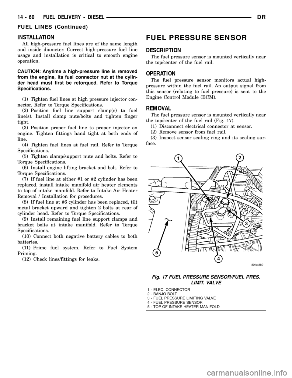
The fuel pressure sensor is mounted vertically near
the top/center of the fuel rail (Fig. 17).
(1) Disconnect electrical connector at sensor.
(2) Remove sensor from fuel rail.
(3) Inspect sensor sealing ring and its sealing sur-
face.
Fig. 17 FUEL PRESSURE SENSOR/FUEL PRES.
LIMIT. VALVE
1 - ELEC. CONNECTOR
2 - BANJO BOLT
3 - FUEL PRESSURE LIMITING VALVE
4 - FUEL PRESSURE SENSOR
5 - TOP OF INTAKE HEATER MANIFOLD
14 - 60 FUEL DELIVERY - DIESELDR
FUEL LINES (Continued)
Page 1630 of 2627
INSTALLATION
(1) Inspect fuel pressure sensor sealing surface.
(2) Lubricate sensor threads with clean diesel fuel.
(3) Install sensor into fuel rail.
(4) To prevent leaks, sensormustbe tightened to
prescribed torque. Refer to Torque Specifications.
(5) Connect electrical connector to sensor.
(6) Start engine and check for fuel leaks.
FUEL PRESSURE LIMITING
VA LV E
DESCRIPTION
The fuel pressure limiting valve is located on the
top of the fuel rail.
OPERATION
Fuel pressure at the fuel rail is monitored by the
fuel rail pressure sensor. If fuel pressure becomes
excessive, the pressure limiting valve opens and
vents excess pressure into the fuel drain circuit.
REMOVAL
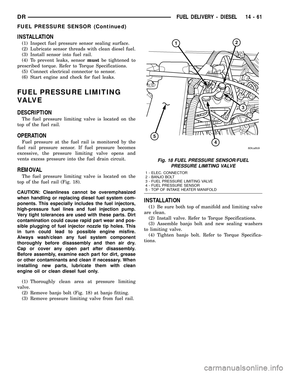
The fuel pressure limiting valve is located on the
top of the fuel rail (Fig. 18).
CAUTION: Cleanliness cannot be overemphasized
when handling or replacing diesel fuel system com-
ponents. This especially includes the fuel injectors,
high-pressure fuel lines and fuel injection pump.
Very tight tolerances are used with these parts. Dirt
contamination could cause rapid part wear and pos-
sible plugging of fuel injector nozzle tip holes. This
in turn could lead to possible engine misfire.
Always wash/clean any fuel system component
thoroughly before disassembly and then air dry.
Cap or cover any open part after disassembly.
Before assembly, examine each part for dirt, grease
or other contaminants and clean if necessary. When
installing new parts, lubricate them with clean
engine oil or clean diesel fuel only.
(1) Thoroughly clean area at pressure limiting
valve.
(2) Remove banjo bolt (Fig. 18) at banjo fitting.
(3) Remove pressure limiting valve from fuel rail.
INSTALLATION
(1) Be sure both top of manifold and limiting valve
are clean.
(2) Install valve. Refer to Torque Specifications.
(3) Assemble banjo bolt and new sealing washers
to limiting valve.
(4) Tighten banjo bolt. Refer to Torque Specifica-
tions.
Fig. 18 FUEL PRESSURE SENSOR/FUEL
PRESSURE LIMITING VALVE
1 - ELEC. CONNECTOR
2 - BANJO BOLT
3 - FUEL PRESSURE LIMITING VALVE
4 - FUEL PRESSURE SENSOR
5 - TOP OF INTAKE HEATER MANIFOLD
DRFUEL DELIVERY - DIESEL 14 - 61
FUEL PRESSURE SENSOR (Continued)