1998 DODGE RAM 1500 water pump
[x] Cancel search: water pumpPage 1382 of 2627
INSTALLATION
(1) Position the oil pump onto the crankshaft and
install one oil pump retaining bolts.
(2) Position the primary timing chain tensioner
and install three retaining bolts.
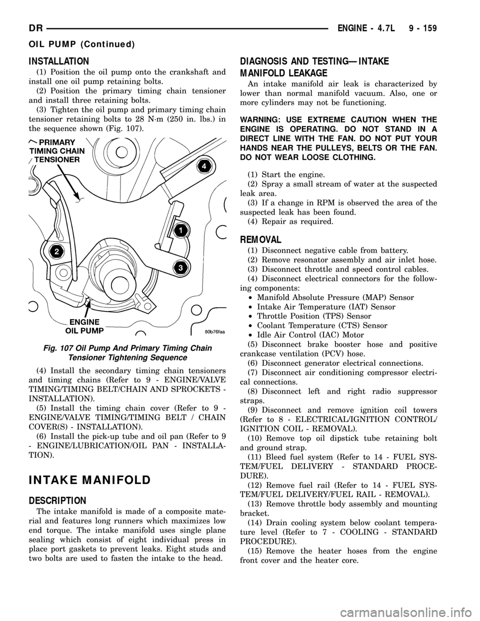
(3) Tighten the oil pump and primary timing chain
tensioner retaining bolts to 28 N´m (250 in. lbs.) in
the sequence shown (Fig. 107).
(4) Install the secondary timing chain tensioners
and timing chains (Refer to 9 - ENGINE/VALVE
TIMING/TIMING BELT/CHAIN AND SPROCKETS -
INSTALLATION).
(5) Install the timing chain cover (Refer to 9 -
ENGINE/VALVE TIMING/TIMING BELT / CHAIN
COVER(S) - INSTALLATION).
(6) Install the pick-up tube and oil pan (Refer to 9
- ENGINE/LUBRICATION/OIL PAN - INSTALLA-
TION).
INTAKE MANIFOLD
DESCRIPTION
The intake manifold is made of a composite mate-
rial and features long runners which maximizes low
end torque. The intake manifold uses single plane
sealing which consist of eight individual press in
place port gaskets to prevent leaks. Eight studs and
two bolts are used to fasten the intake to the head.
DIAGNOSIS AND TESTINGÐINTAKE
MANIFOLD LEAKAGE
An intake manifold air leak is characterized by
lower than normal manifold vacuum. Also, one or
more cylinders may not be functioning.
WARNING: USE EXTREME CAUTION WHEN THE
ENGINE IS OPERATING. DO NOT STAND IN A
DIRECT LINE WITH THE FAN. DO NOT PUT YOUR
HANDS NEAR THE PULLEYS, BELTS OR THE FAN.
DO NOT WEAR LOOSE CLOTHING.
(1) Start the engine.
(2) Spray a small stream of water at the suspected
leak area.
(3) If a change in RPM is observed the area of the
suspected leak has been found.
(4) Repair as required.
REMOVAL
(1) Disconnect negative cable from battery.
(2) Remove resonator assembly and air inlet hose.
(3) Disconnect throttle and speed control cables.
(4) Disconnect electrical connectors for the follow-
ing components:
²Manifold Absolute Pressure (MAP) Sensor
²Intake Air Temperature (IAT) Sensor
²Throttle Position (TPS) Sensor
²Coolant Temperature (CTS) Sensor
²Idle Air Control (IAC) Motor
(5) Disconnect brake booster hose and positive
crankcase ventilation (PCV) hose.
(6) Disconnect generator electrical connections.
(7) Disconnect air conditioning compressor electri-
cal connections.
(8) Disconnect left and right radio suppressor
straps.
(9) Disconnect and remove ignition coil towers
(Refer to 8 - ELECTRICAL/IGNITION CONTROL/
IGNITION COIL - REMOVAL).
(10) Remove top oil dipstick tube retaining bolt
and ground strap.
(11) Bleed fuel system (Refer to 14 - FUEL SYS-
TEM/FUEL DELIVERY - STANDARD PROCE-
DURE).
(12) Remove fuel rail (Refer to 14 - FUEL SYS-
TEM/FUEL DELIVERY/FUEL RAIL - REMOVAL).
(13) Remove throttle body assembly and mounting
bracket.
(14) Drain cooling system below coolant tempera-
ture level (Refer to 7 - COOLING - STANDARD
PROCEDURE).
(15) Remove the heater hoses from the engine
front cover and the heater core.
Fig. 107 Oil Pump And Primary Timing Chain
Tensioner Tightening Sequence
DRENGINE - 4.7L 9 - 159
OIL PUMP (Continued)
Page 1394 of 2627
(7) Remove the generator and A/C compressor.
CAUTION: The 4.7L engine uses an RTV sealer
instead of a gasket to seal the front cover to the
engine block, from the factory. For service, MoparT
Engine RTV sealant must be substituted.
NOTE: It is not necessary to remove the water
pump for timing cover removal.
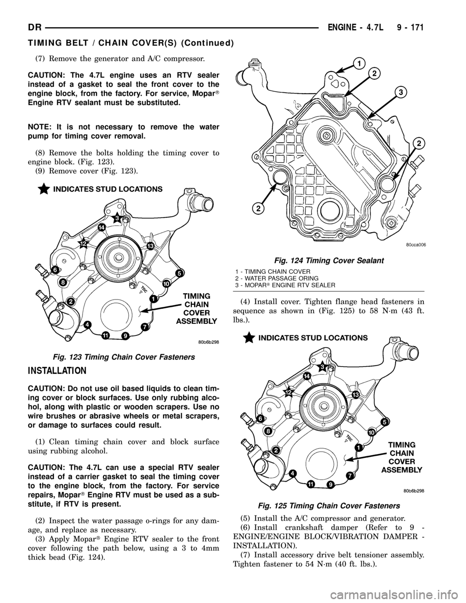
(8) Remove the bolts holding the timing cover to
engine block. (Fig. 123).
(9) Remove cover (Fig. 123).
INSTALLATION
CAUTION: Do not use oil based liquids to clean tim-
ing cover or block surfaces. Use only rubbing alco-
hol, along with plastic or wooden scrapers. Use no
wire brushes or abrasive wheels or metal scrapers,
or damage to surfaces could result.
(1) Clean timing chain cover and block surface
using rubbing alcohol.
CAUTION: The 4.7L can use a special RTV sealer
instead of a carrier gasket to seal the timing cover
to the engine block, from the factory. For service
repairs, MoparTEngine RTV must be used as a sub-
stitute, if RTV is present.
(2) Inspect the water passage o-rings for any dam-
age, and replace as necessary.
(3) Apply MopartEngine RTV sealer to the front
cover following the path below, usinga3to4mm
thick bead (Fig. 124).(4) Install cover. Tighten flange head fasteners in
sequence as shown in (Fig. 125) to 58 N´m (43 ft.
lbs.).
(5) Install the A/C compressor and generator.
(6) Install crankshaft damper (Refer to 9 -
ENGINE/ENGINE BLOCK/VIBRATION DAMPER -
INSTALLATION).
(7) Install accessory drive belt tensioner assembly.
Tighten fastener to 54 N´m (40 ft. lbs.).
Fig. 123 Timing Chain Cover Fasteners
Fig. 124 Timing Cover Sealant
1 - TIMING CHAIN COVER
2 - WATER PASSAGE ORING
3 - MOPARTENGINE RTV SEALER
Fig. 125 Timing Chain Cover Fasteners
DRENGINE - 4.7L 9 - 171
TIMING BELT / CHAIN COVER(S) (Continued)
Page 1406 of 2627
DIAGNOSIS AND TESTING
DIAGNOSIS AND TESTING - ENGINE
DIAGNOSIS - INTRODUCTION
Engine diagnosis is helpful in determining the
causes of malfunctions not detected and remedied by
routine maintenance.
These malfunctions may be classified as either per-
formance (e.g., engine idles rough and stalls) or
mechanical (e.g., a strange noise).
(Refer to 9 - ENGINE - DIAGNOSIS AND TEST-
ING) - PERFORMANCE and (Refer to 9 - ENGINE -
DIAGNOSIS AND TESTING)ÐMECHANICAL for
possible causes and corrections of malfunctions.
(Refer to 14 - FUEL SYSTEM/FUEL DELIVERY -
DIAGNOSIS AND TESTING) and (Refer to 14 -
FUEL SYSTEM/FUEL INJECTION - DIAGNOSIS
AND TESTING) for the fuel system diagnosis.Additional tests and diagnostic procedures may be
necessary for specific engine malfunctions that can
not be isolated with the Service Diagnosis charts.
Information concerning additional tests and diagno-
sis is provided within the following diagnosis:
²Cylinder Compression Pressure Test (Refer to 9 -
ENGINE - DIAGNOSIS AND TESTING).
²Cylinder Combustion Pressure Leakage Test
(Refer to 9 - ENGINE - DIAGNOSIS AND TEST-
ING).
²Engine Cylinder Head Gasket Failure Diagnosis
(Refer to 9 - ENGINE/CYLINDER HEAD - DIAGNO-
SIS AND TESTING).
²Intake Manifold Leakage Diagnosis (Refer to 9 -
ENGINE/MANIFOLDS/INTAKE MANIFOLD -
DIAGNOSIS AND TESTING).
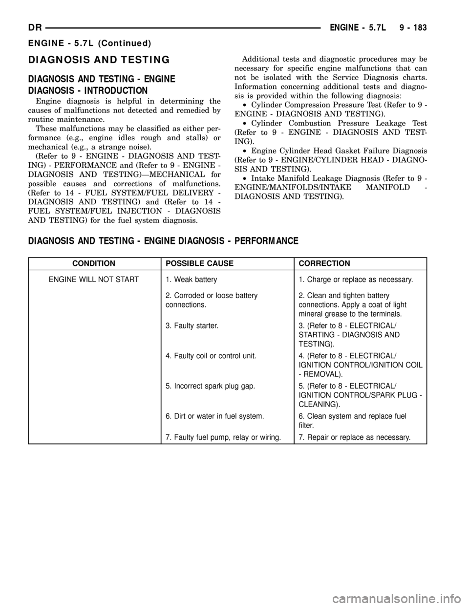
DIAGNOSIS AND TESTING - ENGINE DIAGNOSIS - PERFORMANCE
CONDITION POSSIBLE CAUSE CORRECTION
ENGINE WILL NOT START 1. Weak battery 1. Charge or replace as necessary.
2. Corroded or loose battery
connections.2. Clean and tighten battery
connections. Apply a coat of light
mineral grease to the terminals.
3. Faulty starter. 3. (Refer to 8 - ELECTRICAL/
STARTING - DIAGNOSIS AND
TESTING).
4. Faulty coil or control unit. 4. (Refer to 8 - ELECTRICAL/
IGNITION CONTROL/IGNITION COIL
- REMOVAL).
5. Incorrect spark plug gap. 5. (Refer to 8 - ELECTRICAL/
IGNITION CONTROL/SPARK PLUG -
CLEANING).
6. Dirt or water in fuel system. 6. Clean system and replace fuel
filter.
7. Faulty fuel pump, relay or wiring. 7. Repair or replace as necessary.
DRENGINE - 5.7L 9 - 183
ENGINE - 5.7L (Continued)
Page 1407 of 2627
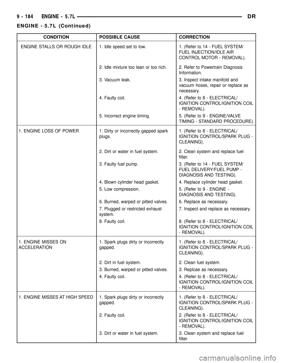
CONDITION POSSIBLE CAUSE CORRECTION
ENGINE STALLS OR ROUGH IDLE 1. Idle speed set to low. 1. (Refer to 14 - FUEL SYSTEM/
FUEL INJECTION/IDLE AIR
CONTROL MOTOR - REMOVAL).
2. Idle mixture too lean or too rich. 2. Refer to Powertrain Diagnosis
Information.
3. Vacuum leak. 3. Inspect intake manifold and
vacuum hoses, repair or replace as
necessary.
4. Faulty coil. 4. (Refer to 8 - ELECTRICAL/
IGNITION CONTROL/IGNITION COIL
- REMOVAL).
5. Incorrect engine timing. 5. (Refer to 9 - ENGINE/VALVE
TIMING - STANDARD PROCEDURE).
1. ENGINE LOSS OF POWER 1. Dirty or incorrectly gapped spark
plugs.1. (Refer to 8 - ELECTRICAL/
IGNITION CONTROL/SPARK PLUG -
CLEANING).
2. Dirt or water in fuel system. 2. Clean system and replace fuel
filter.
3. Faulty fuel pump. 3. (Refer to 14 - FUEL SYSTEM/
FUEL DELIVERY/FUEL PUMP -
DIAGNOSIS AND TESTING).
4. Blown cylinder head gasket. 4. Replace cylinder head gasket.
5. Low compression. 5. (Refer to 9 - ENGINE -
DIAGNOSIS AND TESTING).
6. Burned, warped or pitted valves. 6. Replace as necessary.
7. Plugged or restricted exhaust
system.7. Inspect and replace as necessary.
8. Faulty coil. 8. (Refer to 8 - ELECTRICAL/
IGNITION CONTROL/IGNITION COIL
- REMOVAL).
1. ENGINE MISSES ON
ACCELERATION1. Spark plugs dirty or incorrectly
gapped.1. (Refer to 8 - ELECTRICAL/
IGNITION CONTROL/SPARK PLUG -
CLEANING).
2. Dirt in fuel system. 2. Clean fuel system.
3. Burned, warped or pitted valves. 3. Replcae as necessary.
4. Faulty coil. 4. (Refer to 8 - ELECTRICAL/
IGNITION CONTROL/IGNITION COIL
- REMOVAL).
1. ENGINE MISSES AT HIGH SPEED 1. Spark plugs dirty or incorrectly
gapped.1. (Refer to 8 - ELECTRICAL/
IGNITION CONTROL/SPARK PLUG -
CLEANING).
2. Faulty coil. 2. (Refer to 8 - ELECTRICAL/
IGNITION CONTROL/IGNITION COIL
- REMOVAL).
3. Dirt or water in fuel system. 3. Clean system and replace fuel
filter.
9 - 184 ENGINE - 5.7LDR
ENGINE - 5.7L (Continued)
Page 1419 of 2627
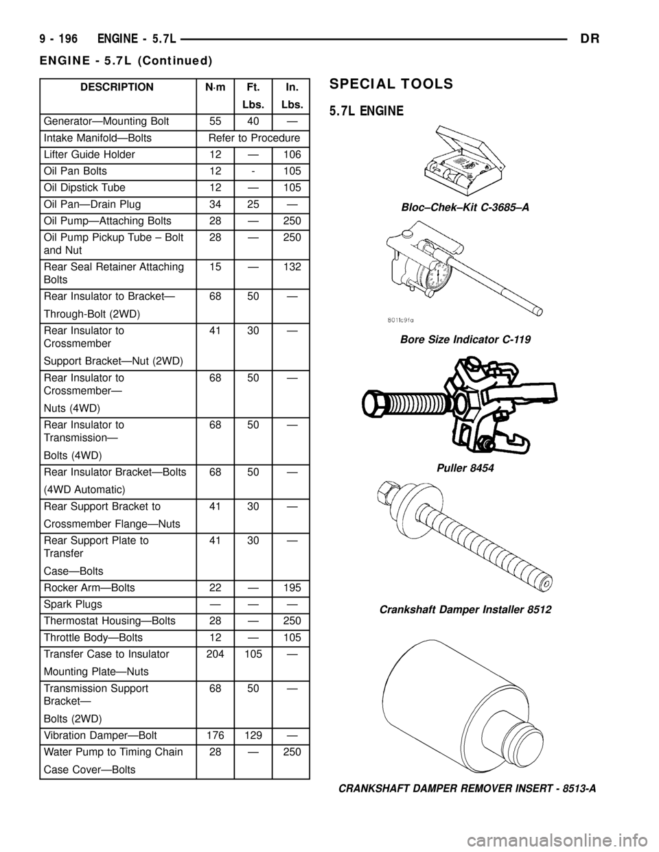
DESCRIPTION N´m Ft. In.
Lbs. Lbs.
GeneratorÐMounting Bolt 55 40 Ð
Intake ManifoldÐBolts Refer to Procedure
Lifter Guide Holder 12 Ð 106
Oil Pan Bolts 12 - 105
Oil Dipstick Tube 12 Ð 105
Oil PanÐDrain Plug 34 25 Ð
Oil PumpÐAttaching Bolts 28 Ð 250
Oil Pump Pickup Tube ± Bolt
and Nut28 Ð 250
Rear Seal Retainer Attaching
Bolts15 Ð 132
Rear Insulator to BracketÐ 68 50 Ð
Through-Bolt (2WD)
Rear Insulator to
Crossmember41 30 Ð
Support BracketÐNut (2WD)
Rear Insulator to
CrossmemberÐ68 50 Ð
Nuts (4WD)
Rear Insulator to
TransmissionÐ68 50 Ð
Bolts (4WD)
Rear Insulator BracketÐBolts 68 50 Ð
(4WD Automatic)
Rear Support Bracket to 41 30 Ð
Crossmember FlangeÐNuts
Rear Support Plate to
Transfer41 30 Ð
CaseÐBolts
Rocker ArmÐBolts 22 Ð 195
Spark Plugs Ð Ð Ð
Thermostat HousingÐBolts 28 Ð 250
Throttle BodyÐBolts 12 Ð 105
Transfer Case to Insulator 204 105 Ð
Mounting PlateÐNuts
Transmission Support
BracketÐ68 50 Ð
Bolts (2WD)
Vibration DamperÐBolt 176 129 Ð
Water Pump to Timing Chain 28 Ð 250
Case CoverÐBoltsSPECIAL TOOLS
5.7L ENGINE
CRANKSHAFT DAMPER REMOVER INSERT - 8513-A
Bloc±Chek±Kit C-3685±A
Bore Size Indicator C-119
Puller 8454
Crankshaft Damper Installer 8512
9 - 196 ENGINE - 5.7LDR
ENGINE - 5.7L (Continued)
Page 1438 of 2627
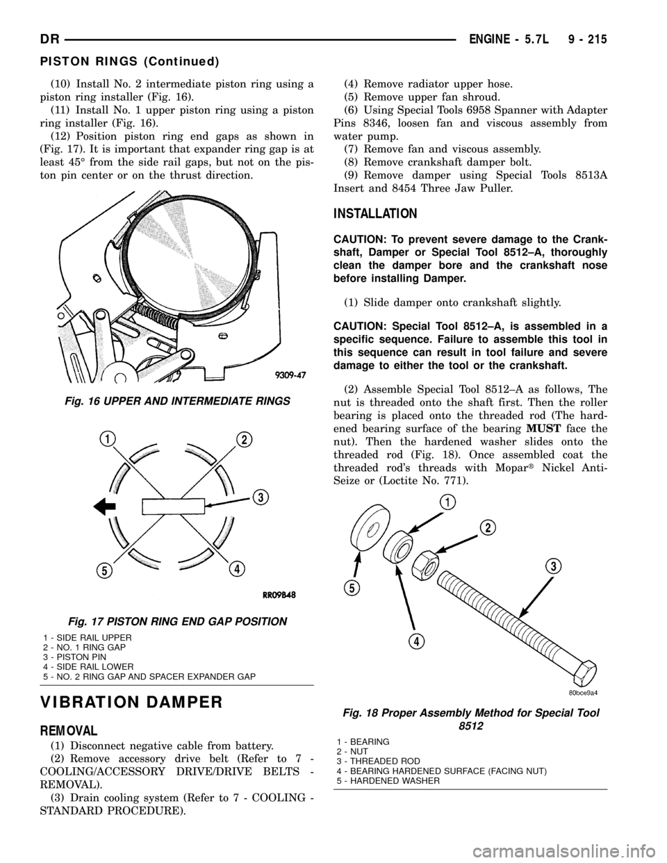
(10) Install No. 2 intermediate piston ring using a
piston ring installer (Fig. 16).
(11) Install No. 1 upper piston ring using a piston
ring installer (Fig. 16).
(12) Position piston ring end gaps as shown in
(Fig. 17). It is important that expander ring gap is at
least 45É from the side rail gaps, but not on the pis-
ton pin center or on the thrust direction.
VIBRATION DAMPER
REMOVAL
(1) Disconnect negative cable from battery.
(2) Remove accessory drive belt (Refer to 7 -
COOLING/ACCESSORY DRIVE/DRIVE BELTS -
REMOVAL).
(3) Drain cooling system (Refer to 7 - COOLING -
STANDARD PROCEDURE).(4) Remove radiator upper hose.
(5) Remove upper fan shroud.
(6) Using Special Tools 6958 Spanner with Adapter
Pins 8346, loosen fan and viscous assembly from
water pump.
(7) Remove fan and viscous assembly.
(8) Remove crankshaft damper bolt.
(9) Remove damper using Special Tools 8513A
Insert and 8454 Three Jaw Puller.
INSTALLATION
CAUTION: To prevent severe damage to the Crank-
shaft, Damper or Special Tool 8512±A, thoroughly
clean the damper bore and the crankshaft nose
before installing Damper.
(1) Slide damper onto crankshaft slightly.
CAUTION: Special Tool 8512±A, is assembled in a
specific sequence. Failure to assemble this tool in
this sequence can result in tool failure and severe
damage to either the tool or the crankshaft.
(2) Assemble Special Tool 8512±A as follows, The
nut is threaded onto the shaft first. Then the roller
bearing is placed onto the threaded rod (The hard-
ened bearing surface of the bearingMUSTface the
nut). Then the hardened washer slides onto the
threaded rod (Fig. 18). Once assembled coat the
threaded rod's threads with MopartNickel Anti-
Seize or (Loctite No. 771).
Fig. 16 UPPER AND INTERMEDIATE RINGS
Fig. 17 PISTON RING END GAP POSITION
1 - SIDE RAIL UPPER
2 - NO. 1 RING GAP
3 - PISTON PIN
4 - SIDE RAIL LOWER
5 - NO. 2 RING GAP AND SPACER EXPANDER GAP
Fig. 18 Proper Assembly Method for Special Tool
8512
1 - BEARING
2 - NUT
3 - THREADED ROD
4 - BEARING HARDENED SURFACE (FACING NUT)
5 - HARDENED WASHER
DRENGINE - 5.7L 9 - 215
PISTON RINGS (Continued)
Page 1448 of 2627
NOTE: The 5.7 Oil pump is released as an assem-
bly. There are no DaimlerChrysler part numbers for
Sub-Assembly components. In the event the oil
pump is not functioning or out of specification it
must be replaced as an assembly.
INSTALLATION
(1) Position the oil pump onto the crankshaft and
install the 4 oil pump retaining bolts.(2) Tighten the oil pump retaining bolts to 28 N´m
(250 in. lbs.).
(3) Install the timing chain cover(Refer to 9 -
ENGINE/VALVE TIMING/TIMING BELT / CHAIN
COVER(S) - INSTALLATION).
(4) Install the pick-up tube and oil pan(Refer to 9 -
ENGINE/LUBRICATION/OIL PAN - INSTALLA-
TION).
INTAKE MANIFOLD
DESCRIPTION
The intake manifold is made of a composite mate-
rial and features long runners which maximizes low
end torque. The intake manifold uses single plane
sealing which consist of eight individual press in
place port gaskets to prevent leaks.
DIAGNOSIS AND TESTING - INTAKE
MANIFOLD LEAKAGE
An intake manifold air leak is characterized by
lower than normal manifold vacuum. Also, one or
more cylinders may not be functioning.
WARNING: USE EXTREME CAUTION WHEN THE
ENGINE IS OPERATING. DO NOT STAND IN A
DIRECT LINE WITH THE FAN. DO NOT PUT YOUR
HANDS NEAR THE PULLEYS, BELTS OR THE FAN.
DO NOT WEAR LOOSE CLOTHING.
(1) Start the engine.
(2) Spray a small stream of water at the suspected
leak area.
(3) If a change in RPM is observed the area of the
suspected leak has been found.
(4) Repair as required.
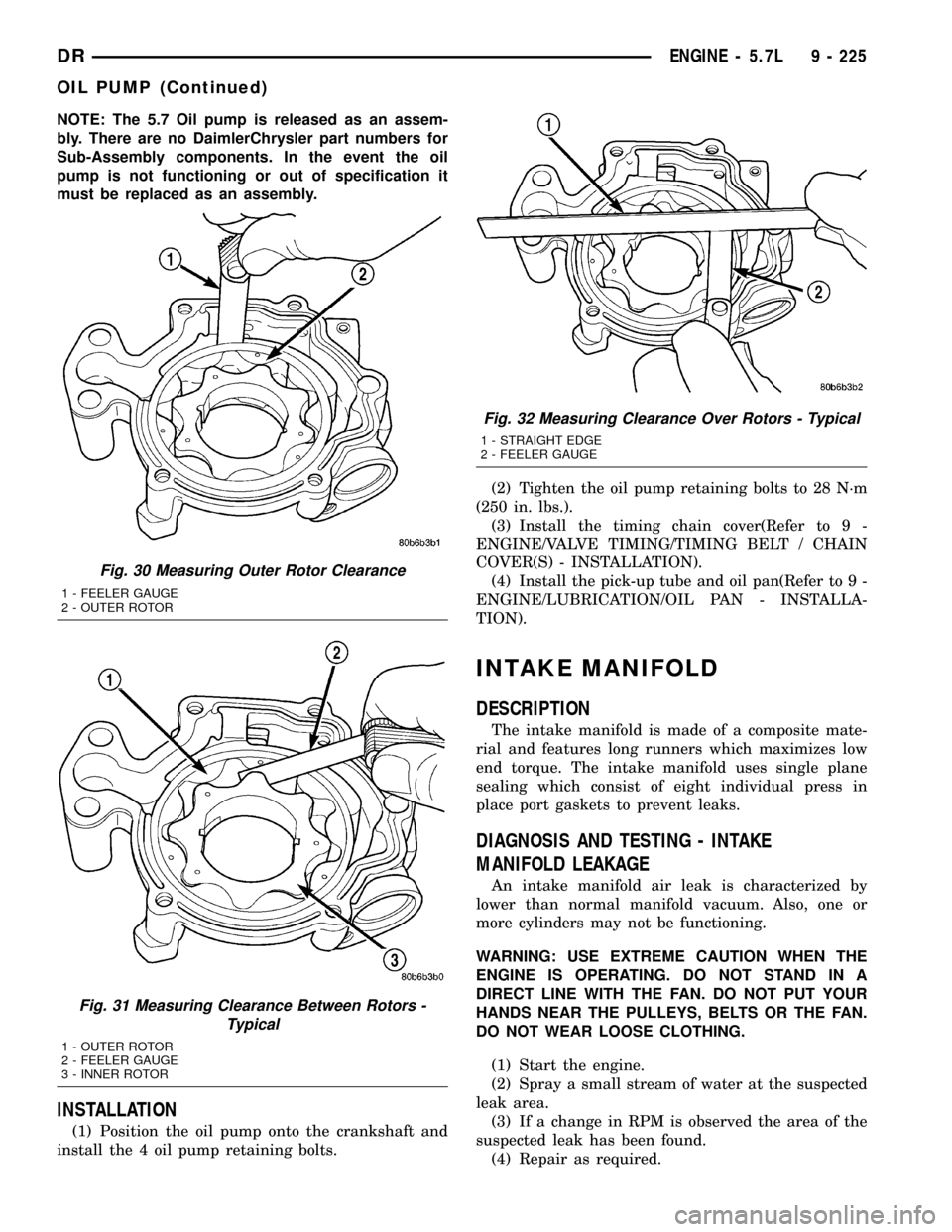
Fig. 30 Measuring Outer Rotor Clearance
1 - FEELER GAUGE
2 - OUTER ROTOR
Fig. 31 Measuring Clearance Between Rotors -
Typical
1 - OUTER ROTOR
2 - FEELER GAUGE
3 - INNER ROTOR
Fig. 32 Measuring Clearance Over Rotors - Typical
1 - STRAIGHT EDGE
2 - FEELER GAUGE
DRENGINE - 5.7L 9 - 225
OIL PUMP (Continued)
Page 1450 of 2627
INSPECTION
Inspect manifold for cracks.
Inspect mating surfaces of manifold for flatness
with a straight edge. Gasket surfaces must be flat
within 0.2 mm per 300 mm (0.008 inch per foot).
INSTALLATION
EXHAUST MANIFOLD
(1) Install manifold gasket and manifold.
(2) Install manifold bolts and tighten to 25 N´m
(18 ft. lbs.).
(3) Install heat shield and tighten nuts to 15 N´m
(11 ft. lbs.).
(4) Lower engine.
CAUTION: Do not damage engine harness while
lowering the engine.
(5) Remove engine support fixture from engine.
(6) Raise vehicle.
(7) Tighten right and left side engine mount
through bolts.
(8) Install exhaust flange to pipe bolts.
(9) Lower vehicle.
(10) Connect negative battery cable.
TIMING/CHAIN COVER
REMOVAL
(1) Disconnect the battery negative cable.
(2) Remove air cleaner assembly.
(3) Drain cooling system.
(4) Remove accessory drive belt.
(5) Remove fan and fan drive assembly (Refer to 7
- COOLING/ENGINE/FAN DRIVE VISCOUS
CLUTCH - REMOVAL).
(6) Remove coolant bottle and washer bottle.
(7) Remove fan shroud.
NOTE: It is not necessary to disconnect A/C lines or
discharge freon.
(8) Remove A/C compressor and set aside.
(9) Remove the generator.
(10) Remove upper radiator hose.
(11) Disconnect both heater hoses at timing cover.
(12) Disconnect lower radiator hose at engine.
(13) Remove accessory drive belt tensioner and
both idler pulleys.
(14) Remove crankshaft damper(Refer to 9 -
ENGINE/ENGINE BLOCK/VIBRATION DAMPER -
REMOVAL).NOTE: Do not remove the hoses from the power
steering pump.
(15) Remove power steering pump and set aside.
(16) Remove the dipstick support bolt.
(17) Drain the engine oil.
(18) Remove the oil pan and pick up tube(Refer to
9 - ENGINE/LUBRICATION/OIL PAN - REMOVAL).
NOTE: It is not necessary to remove water pump for
timing cover removal.
(19) Remove timing cover bolts and remove cover.
INSTALLATION
(1) Clean timing chain cover and block surface.
NOTE: Always install a new gasket on timing cover.
(2) Install cover and new gasket. Tighten fasteners
to 28 N´m (250 in. lbs.).
NOTE: The large lifting stud is torqued to 55 N´m
(40 ft. lbs.).
(3) Install the oil pan and pick up tube(Refer to 9 -
ENGINE/LUBRICATION/OIL PAN - INSTALLA-
TION).
(4) Install the A/C compressor.
(5) Install the generator.
(6) Install power steering pump.
(7) Install the dipstick support bolt.
(8) Install the thermostat housing.
(9) Install crankshaft damper(Refer to 9 -
ENGINE/ENGINE BLOCK/VIBRATION DAMPER -
INSTALLATION).
(10) Install accessory drive belt tensioner assembly
and both idler pulleys.
(11) Install radiator lower hose.
(12) Install both heater hoses.
(13) Install radiator fan shroud.
(14) Install the fan and fan drive assembly
(15) Install the accessory drive belt.
(16) Install the coolant bottle and washer bottle.
(17) Install the upper radiator hose.
(18) Install the air cleaner assembly.
(19) Fill cooling system.
(20) Refill engine oil.
(21) Connect the battery negative cable.
DRENGINE - 5.7L 9 - 227
EXHAUST MANIFOLD (Continued)