1998 DODGE RAM 1500 water pump
[x] Cancel search: water pumpPage 1239 of 2627
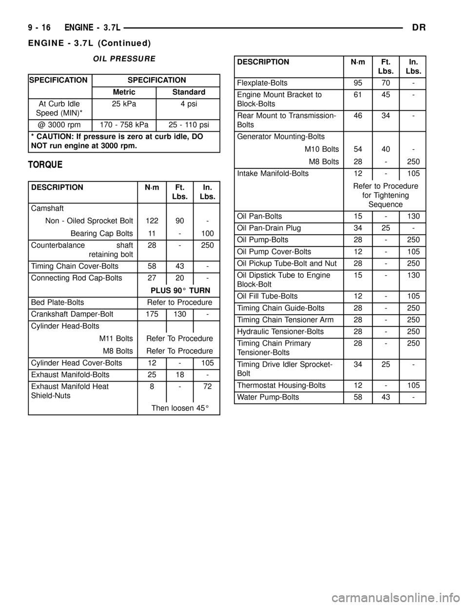
OIL PRESSURE
SPECIFICATION SPECIFICATION
Metric Standard
At Curb Idle
Speed (MIN)*25 kPa 4 psi
@ 3000 rpm 170 - 758 kPa 25 - 110 psi
* CAUTION: If pressure is zero at curb idle, DO
NOT run engine at 3000 rpm.
TORQUE
DESCRIPTION N´m Ft.
Lbs.In.
Lbs.
Camshaft
Non - Oiled Sprocket Bolt 122 90 -
Bearing Cap Bolts 11 - 100
Counterbalance shaft
retaining bolt28 - 250
Timing Chain Cover-Bolts 58 43 -
Connecting Rod Cap-Bolts 27 20 -
PLUS 90É TURN
Bed Plate-Bolts Refer to Procedure
Crankshaft Damper-Bolt 175 130 -
Cylinder Head-Bolts
M11 Bolts Refer To Procedure
M8 Bolts Refer To Procedure
Cylinder Head Cover-Bolts 12 - 105
Exhaust Manifold-Bolts 25 18 -
Exhaust Manifold Heat
Shield-Nuts8-72
Then loosen 45É
DESCRIPTION N´m Ft.
Lbs.In.
Lbs.
Flexplate-Bolts 95 70 -
Engine Mount Bracket to
Block-Bolts61 45 -
Rear Mount to Transmission-
Bolts46 34 -
Generator Mounting-Bolts
M10 Bolts 54 40 -
M8 Bolts 28 - 250
Intake Manifold-Bolts 12 - 105
Refer to Procedure
for Tightening
Sequence
Oil Pan-Bolts 15 - 130
Oil Pan-Drain Plug 34 25 -
Oil Pump-Bolts 28 - 250
Oil Pump Cover-Bolts 12 - 105
Oil Pickup Tube-Bolt and Nut 28 - 250
Oil Dipstick Tube to Engine
Block-Bolt15 - 130
Oil Fill Tube-Bolts 12 - 105
Timing Chain Guide-Bolts 28 - 250
Timing Chain Tensioner Arm 28 - 250
Hydraulic Tensioner-Bolts 28 - 250
Timing Chain Primary
Tensioner-Bolts28 - 250
Timing Drive Idler Sprocket-
Bolt34 25 -
Thermostat Housing-Bolts 12 - 105
Water Pump-Bolts 58 43 -
9 - 16 ENGINE - 3.7LDR
ENGINE - 3.7L (Continued)
Page 1245 of 2627
²Excessive steam (white smoke) emitting from
exhaust
²Coolant foaming
CYLINDER-TO-CYLINDER LEAKAGE TEST
To determine if an engine cylinder head gasket is
leaking between adjacent cylinders, follow the proce-
dures in Cylinder Compression Pressure Test (Refer
to 9 - ENGINE - DIAGNOSIS AND TESTING). An
engine cylinder head gasket leaking between adja-
cent cylinders will result in approximately a 50 - 70%
reduction in compression pressure.
CYLINDER-TO-WATER JACKET LEAKAGE TEST
WARNING: USE EXTREME CAUTION WHEN THE
ENGINE IS OPERATING WITH COOLANT PRES-
SURE CAP REMOVED.
VISUAL TEST METHOD
With the engine cool, remove the coolant pressure
cap. Start the engine and allow it to warm up until
thermostat opens.
If a large combustion/compression pressure leak
exists, bubbles will be visible in the coolant.
COOLING SYSTEM TESTER METHOD
WARNING: WITH COOLING SYSTEM TESTER IN
PLACE, PRESSURE WILL BUILD UP FAST. EXCES-
SIVE PRESSURE BUILT UP, BY CONTINUOUS
ENGINE OPERATION, MUST BE RELEASED TO A
SAFE PRESSURE POINT. NEVER PERMIT PRES-
SURE TO EXCEED 138 kPa (20 psi).
Install Cooling System Tester 7700 or equivalent to
pressure cap neck. Start the engine and observe the
tester's pressure gauge. If gauge pulsates with every
power stroke of a cylinder a combustion pressure
leak is evident.
CHEMICAL TEST METHOD
Combustion leaks into the cooling system can also
be checked by using Bloc-Chek Kit C-3685-A or
equivalent. Perform test following the procedures
supplied with the tool kit.
REMOVAL
(1) Disconnect the negative cable from the battery.
(2) Raise the vehicle on a hoist.
(3) Disconnect the exhaust pipe at the left side
exhaust manifold.
(4) Drain the engine coolant(Refer to 7 - COOL-
ING - STANDARD PROCEDURE).
(5) Lower the vehicle.(6) Remove the intake manifold(Refer to 9 -
ENGINE/MANIFOLDS/INTAKE MANIFOLD -
REMOVAL).
(7) Remove the master cylinder and booster assem-
bly(Refer to 5 - BRAKES/HYDRAULIC/MECHANI-
CAL/POWER BRAKE BOOSTER - REMOVAL).
(8) Remove the cylinder head cover(Refer to 9 -
ENGINE/CYLINDER HEAD/CYLINDER HEAD
COVER(S) - REMOVAL).
(9) Remove the fan shroud and fan blade assem-
bly(Refer to 7 - COOLING/ENGINE/RADIATOR FAN
- REMOVAL).
(10) Remove accessory drive belt(Refer to 7 -
COOLING/ACCESSORY DRIVE/DRIVE BELTS -
REMOVAL).
(11) Remove the power steering pump and set
aside.
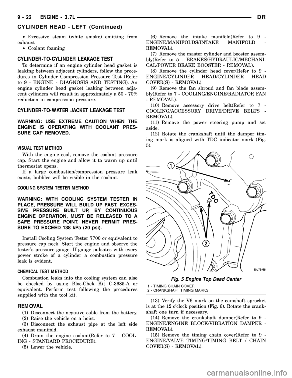
(12) Rotate the crankshaft until the damper tim-
ing mark is aligned with TDC indicator mark (Fig.
5).
(13) Verify the V6 mark on the camshaft sprocket
is at the 12 o'clock position (Fig. 6). Rotate the crank-
shaft one turn if necessary.
(14) Remove the crankshaft damper(Refer to 9 -
ENGINE/ENGINE BLOCK/VIBRATION DAMPER -
REMOVAL).
(15) Remove the timing chain cover(Refer to 9 -
ENGINE/VALVE TIMING/TIMING BELT / CHAIN
COVER(S) - REMOVAL).
Fig. 5 Engine Top Dead Center
1 - TIMING CHAIN COVER
2 - CRANKSHAFT TIMING MARKS
9 - 22 ENGINE - 3.7LDR
CYLINDER HEAD - LEFT (Continued)
Page 1278 of 2627
(8) Install the oil ring expander.
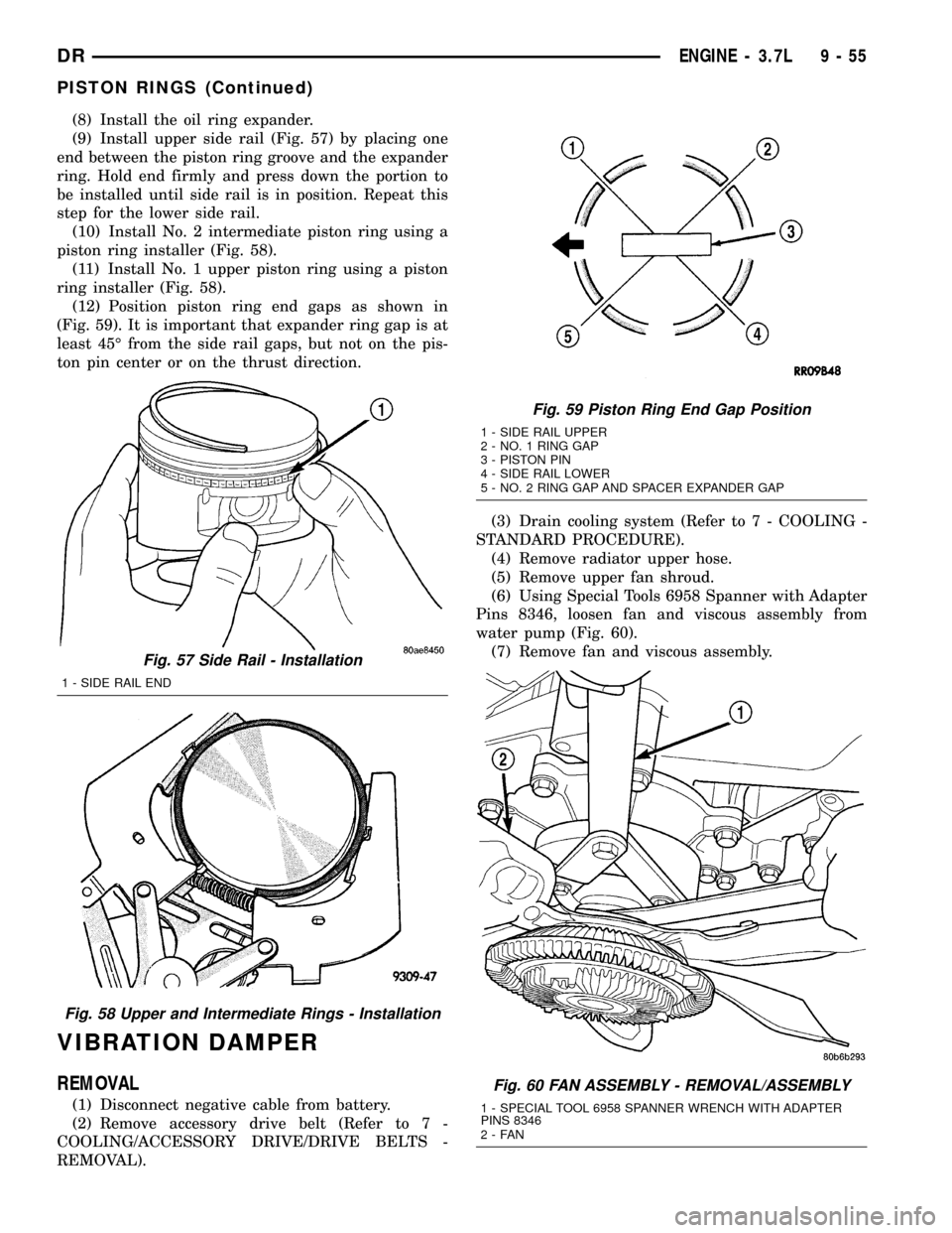
(9) Install upper side rail (Fig. 57) by placing one
end between the piston ring groove and the expander
ring. Hold end firmly and press down the portion to
be installed until side rail is in position. Repeat this
step for the lower side rail.
(10) Install No. 2 intermediate piston ring using a
piston ring installer (Fig. 58).
(11) Install No. 1 upper piston ring using a piston
ring installer (Fig. 58).
(12) Position piston ring end gaps as shown in
(Fig. 59). It is important that expander ring gap is at
least 45É from the side rail gaps, but not on the pis-
ton pin center or on the thrust direction.
VIBRATION DAMPER
REMOVAL
(1) Disconnect negative cable from battery.
(2) Remove accessory drive belt (Refer to 7 -
COOLING/ACCESSORY DRIVE/DRIVE BELTS -
REMOVAL).(3) Drain cooling system (Refer to 7 - COOLING -
STANDARD PROCEDURE).
(4) Remove radiator upper hose.
(5) Remove upper fan shroud.
(6) Using Special Tools 6958 Spanner with Adapter
Pins 8346, loosen fan and viscous assembly from
water pump (Fig. 60).
(7) Remove fan and viscous assembly.
Fig. 57 Side Rail - Installation
1 - SIDE RAIL END
Fig. 58 Upper and Intermediate Rings - Installation
Fig. 59 Piston Ring End Gap Position
1 - SIDE RAIL UPPER
2 - NO. 1 RING GAP
3 - PISTON PIN
4 - SIDE RAIL LOWER
5 - NO. 2 RING GAP AND SPACER EXPANDER GAP
Fig. 60 FAN ASSEMBLY - REMOVAL/ASSEMBLY
1 - SPECIAL TOOL 6958 SPANNER WRENCH WITH ADAPTER
PINS 8346
2-FAN
DRENGINE - 3.7L 9 - 55
PISTON RINGS (Continued)
Page 1304 of 2627
IDLER SHAFT
REMOVAL
(1) Remove the primary and secondary timing
chains and sprockets. Refer to procedure in this sec-
tion.
NOTE: To remove the idler shaft, it is necessary to
tap threads into the shaft, to install the removal
tool.
(2) Using a 12 mm X 1.75 tap, cut threads in the
idler shaft center bore.
(3) Cover the radiator core with a suitable cover.
CAUTION: Use care when removing the idler shaft,
Do not strike the radiator cooling fins with the slide
hammer.
(4) Using Special Tool 8517 Slide Hammer, remove
the idler shaft.
INSTALLATION
(1) Thoroughly clean the idler shaft bore.
(2) Position the idler shaft in the bore.
NOTE: The two lubrication holes in the idler shaft
do not require any special alignment.
NOTE: Before using the retaining bolt to install the
idler shaft, coat the threads and the pilot on the
idler shaft, with clean engine oil.
(3) Using the primary idler sprocket retaining bolt
and washer, carefully draw the idler shaft into the
bore until fully seated.
(4) Coat the idler shaft with clean engine oil.
(5) Install the timing chains and sprockets. Refer
to procedure in this section.
TIMING BELT / CHAIN
COVER(S)
REMOVAL
(1) Disconnect the battery negative cable.
(2) Drain cooling system (Refer to 7 - COOLING -
STANDARD PROCEDURE).
(3) Remove electric cooling fan and fan shroud
assembly.
(4) Remove fan and fan drive assembly (Refer to 7
- COOLING/ENGINE/FAN DRIVE VISCOUS
CLUTCH - REMOVAL).
(5) Disconnect both heater hoses at timing cover.
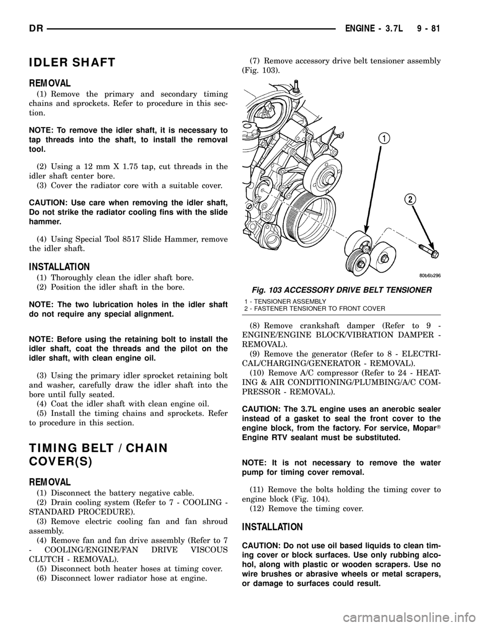
(6) Disconnect lower radiator hose at engine.(7) Remove accessory drive belt tensioner assembly
(Fig. 103).
(8) Remove crankshaft damper (Refer to 9 -
ENGINE/ENGINE BLOCK/VIBRATION DAMPER -
REMOVAL).
(9) Remove the generator (Refer to 8 - ELECTRI-
CAL/CHARGING/GENERATOR - REMOVAL).
(10) Remove A/C compressor (Refer to 24 - HEAT-
ING & AIR CONDITIONING/PLUMBING/A/C COM-
PRESSOR - REMOVAL).
CAUTION: The 3.7L engine uses an anerobic sealer
instead of a gasket to seal the front cover to the
engine block, from the factory. For service, MoparT
Engine RTV sealant must be substituted.
NOTE: It is not necessary to remove the water
pump for timing cover removal.
(11) Remove the bolts holding the timing cover to
engine block (Fig. 104).
(12) Remove the timing cover.
INSTALLATION
CAUTION: Do not use oil based liquids to clean tim-
ing cover or block surfaces. Use only rubbing alco-
hol, along with plastic or wooden scrapers. Use no
wire brushes or abrasive wheels or metal scrapers,
or damage to surfaces could result.
Fig. 103 ACCESSORY DRIVE BELT TENSIONER
1 - TENSIONER ASSEMBLY
2 - FASTENER TENSIONER TO FRONT COVER
DRENGINE - 3.7L 9 - 81
Page 1313 of 2627
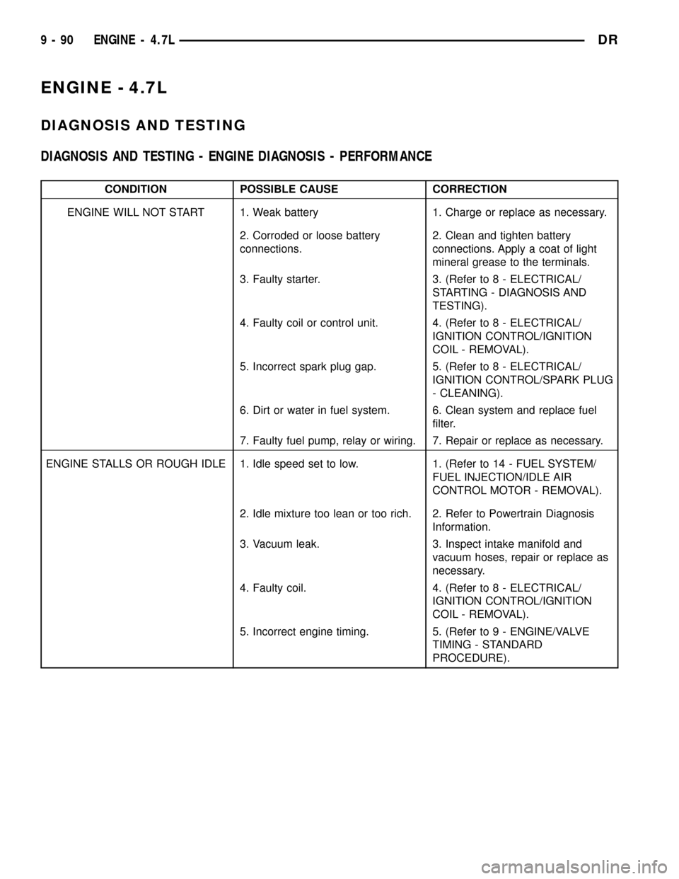
ENGINE - 4.7L
DIAGNOSIS AND TESTING
DIAGNOSIS AND TESTING - ENGINE DIAGNOSIS - PERFORMANCE
CONDITION POSSIBLE CAUSE CORRECTION
ENGINE WILL NOT START 1. Weak battery 1. Charge or replace as necessary.
2. Corroded or loose battery
connections.2. Clean and tighten battery
connections. Apply a coat of light
mineral grease to the terminals.
3. Faulty starter. 3. (Refer to 8 - ELECTRICAL/
STARTING - DIAGNOSIS AND
TESTING).
4. Faulty coil or control unit. 4. (Refer to 8 - ELECTRICAL/
IGNITION CONTROL/IGNITION
COIL - REMOVAL).
5. Incorrect spark plug gap. 5. (Refer to 8 - ELECTRICAL/
IGNITION CONTROL/SPARK PLUG
- CLEANING).
6. Dirt or water in fuel system. 6. Clean system and replace fuel
filter.
7. Faulty fuel pump, relay or wiring. 7. Repair or replace as necessary.
ENGINE STALLS OR ROUGH IDLE 1. Idle speed set to low. 1. (Refer to 14 - FUEL SYSTEM/
FUEL INJECTION/IDLE AIR
CONTROL MOTOR - REMOVAL).
2. Idle mixture too lean or too rich. 2. Refer to Powertrain Diagnosis
Information.
3. Vacuum leak. 3. Inspect intake manifold and
vacuum hoses, repair or replace as
necessary.
4. Faulty coil. 4. (Refer to 8 - ELECTRICAL/
IGNITION CONTROL/IGNITION
COIL - REMOVAL).
5. Incorrect engine timing. 5. (Refer to 9 - ENGINE/VALVE
TIMING - STANDARD
PROCEDURE).
9 - 90 ENGINE - 4.7LDR
Page 1314 of 2627
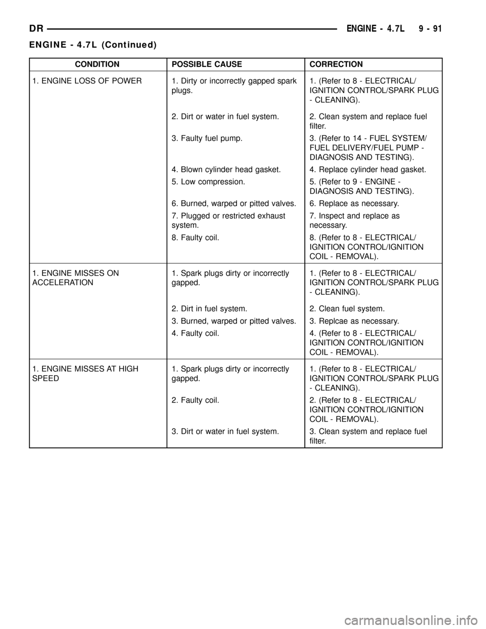
CONDITION POSSIBLE CAUSE CORRECTION
1. ENGINE LOSS OF POWER 1. Dirty or incorrectly gapped spark
plugs.1. (Refer to 8 - ELECTRICAL/
IGNITION CONTROL/SPARK PLUG
- CLEANING).
2. Dirt or water in fuel system. 2. Clean system and replace fuel
filter.
3. Faulty fuel pump. 3. (Refer to 14 - FUEL SYSTEM/
FUEL DELIVERY/FUEL PUMP -
DIAGNOSIS AND TESTING).
4. Blown cylinder head gasket. 4. Replace cylinder head gasket.
5. Low compression. 5. (Refer to 9 - ENGINE -
DIAGNOSIS AND TESTING).
6. Burned, warped or pitted valves. 6. Replace as necessary.
7. Plugged or restricted exhaust
system.7. Inspect and replace as
necessary.
8. Faulty coil. 8. (Refer to 8 - ELECTRICAL/
IGNITION CONTROL/IGNITION
COIL - REMOVAL).
1. ENGINE MISSES ON
ACCELERATION1. Spark plugs dirty or incorrectly
gapped.1. (Refer to 8 - ELECTRICAL/
IGNITION CONTROL/SPARK PLUG
- CLEANING).
2. Dirt in fuel system. 2. Clean fuel system.
3. Burned, warped or pitted valves. 3. Replcae as necessary.
4. Faulty coil. 4. (Refer to 8 - ELECTRICAL/
IGNITION CONTROL/IGNITION
COIL - REMOVAL).
1. ENGINE MISSES AT HIGH
SPEED1. Spark plugs dirty or incorrectly
gapped.1. (Refer to 8 - ELECTRICAL/
IGNITION CONTROL/SPARK PLUG
- CLEANING).
2. Faulty coil. 2. (Refer to 8 - ELECTRICAL/
IGNITION CONTROL/IGNITION
COIL - REMOVAL).
3. Dirt or water in fuel system. 3. Clean system and replace fuel
filter.
DRENGINE - 4.7L 9 - 91
ENGINE - 4.7L (Continued)
Page 1326 of 2627
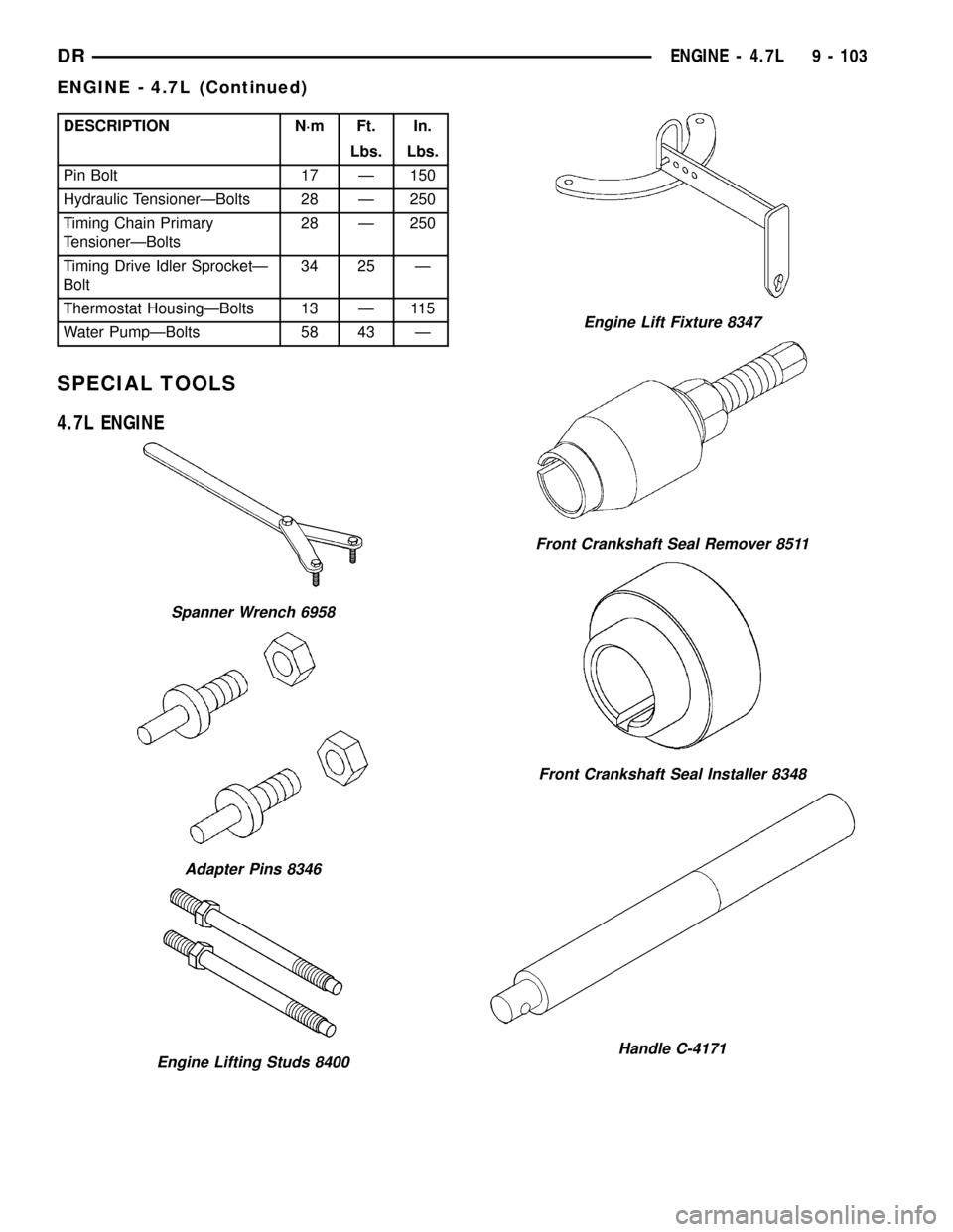
DESCRIPTION N´m Ft. In.
Lbs. Lbs.
Pin Bolt 17 Ð 150
Hydraulic TensionerÐBolts 28 Ð 250
Timing Chain Primary
TensionerÐBolts28 Ð 250
Timing Drive Idler SprocketÐ
Bolt34 25 Ð
Thermostat HousingÐBolts 13 Ð 115
Water PumpÐBolts 58 43 Ð
SPECIAL TOOLS
4.7L ENGINE
Spanner Wrench 6958
Adapter Pins 8346
Engine Lifting Studs 8400
Engine Lift Fixture 8347
Front Crankshaft Seal Remover 8511
Front Crankshaft Seal Installer 8348
Handle C-4171
DRENGINE - 4.7L 9 - 103
ENGINE - 4.7L (Continued)
Page 1367 of 2627
VIBRATION DAMPER
REMOVAL
(1) Disconnect negative cable from battery.
(2) Remove accessory drive belt (Refer to 7 -
COOLING/ACCESSORY DRIVE/DRIVE BELTS -
REMOVAL).
(3) Drain cooling system (Refer to 7 - COOLING -
STANDARD PROCEDURE).
(4) Remove radiator upper hose.
(5) Remove upper fan shroud.
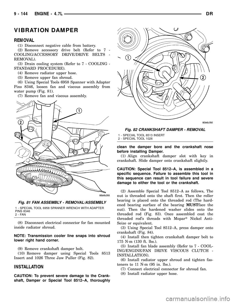
(6) Using Special Tools 6958 Spanner with Adapter
Pins 8346, loosen fan and viscous assembly from
water pump (Fig. 81).
(7) Remove fan and viscous assembly.
(8) Disconnect electrical connector for fan mounted
inside radiator shroud.
NOTE: Transmission cooler line snaps into shroud
lower right hand corner.
(9) Remove crankshaft damper bolt.
(10) Remove damper using Special Tools 8513
Insert and 1026 Three Jaw Puller (Fig. 82).
INSTALLATION
CAUTION: To prevent severe damage to the Crank-
shaft, Damper or Special Tool 8512±A, thoroughlyclean the damper bore and the crankshaft nose
before installing Damper.
(1) Align crankshaft damper slot with key in
crankshaft. Slide damper onto crankshaft slightly.
CAUTION: Special Tool 8512±A, is assembled in a
specific sequence. Failure to assemble this tool in
this sequence can result in tool failure and severe
damage to either the tool or the crankshaft.
(2) Assemble Special Tool 8512±A as follows, The
nut is threaded onto the shaft first. Then the roller
bearing is placed onto the threaded rod (The hard-
ened bearing surface of the bearingMUSTface the
nut). Then the hardened washer slides onto the
threaded rod (Fig. 83). Once assembled coat the
threaded rod's threads with MopartNickel Anti-
Seize or equivalent.
(3) Using Special Tool 8512±A, press damper onto
crankshaft (Fig. 84).
(4) Install then tighten crankshaft damper bolt to
175 N´m (130 ft. lbs.).
(5) Install fan blade assembly (Refer to 7 - COOL-
ING/ENGINE/FAN DRIVE VISCOUS CLUTCH -
INSTALLATION).
(6) Install radiator upper shroud and tighten fas-
teners to 11 N´m (95 in. lbs.).
(7) Connect electrical connector for shroud fan.
(8) Install radiator upper hose.
Fig. 81 FAN ASSEMBLY - REMOVAL/ASSEMBLY
1 - SPECIAL TOOL 6958 SPANNER WRENCH WITH ADAPTER
PINS 8346
2-FAN
Fig. 82 CRANKSHAFT DAMPER - REMOVAL
1 - SPECIAL TOOL 8513 INSERT
2 - SPECIAL TOOL 1026
9 - 144 ENGINE - 4.7LDR