Page 245 of 1680

ECM CONNECTOR D (16P}
Wire side of female terminals
ECM CONNECTOR D (16P1NOTE| Standard battery voltage is 12 V.
TerminalnumberWirecolorT6rminal nameDoscriptionSignal
1RED/BLKTPS (THROTTLE POSITIONSENSOR)Detects TP sensor s;gnal.With throttle fully open: about 4.5 VWith throttle fully closed: about 0.5 V
2REDAr'r'HTECT (ENGINE COOLANTTEMPERATUBE SENSOB}Detects ECT sensor signal.With ignition switch ON (ll)r about0.1 - 4.8 V (depending on engine coolanttemperalure)
3WHT//ELMAP {MANIFOLD AESOLUTEPBESSURE SENSOR)Detects MAP sensor signal.With ignition switch ON (ll)iabout 3 VAt idle: about 1.0 V {depending on enginespeeol
4YELA/VHTvccl{SENSOR VOLTAGE)Power source for MAP sensor,With ignition switch ON (ll): about 5 V
5GRNAVHTBKSW (BRAKE SWITCH)Detects brake switch signal.With brake pedal released: 0 VWith brake pedal depressed: batteryvoltage
6*!RED/BLUKS (KNOCK SENSOR}Detects KS signal.With engine running: pulses
lPHO2S (PRIMARY HEATEDOXYGEN GENSOR)Detects primary oxygen sensorsignal.With throttle fully opened, fully warmed upengine: above 0.6 VWith throttle quickly closed: below 0.4 V
8RED/VEL
IAT (INTAKE AIRTEMPERATURE SENSOR)Detects IAT sensor signal.With ignition switch ON {ll): about0.1 - 4.8 V (depending on intake airtemperature)
10YEL/BLUvcc2(SENSOB VOLTAGE)Provides sensor voltage,With ignition switch ON (ll): about 5 VWith ignition switch OFF: 0 V
1lGRN/8LUSG2 (SENSOR GROUND}Sensor ground.Less than 1.0 V at all times.
GFNA/VHT(SENSOR GROUND}Ground tor MAP sensor.Less than 1.0 V at all times.
OBN/BLUSHO2S GND (SECONDARY
HEATED OXYGEN SENSORGROUND)
Ground for secondary heatedoxygen sensor,Less than 1.0 V at alltimes.
148LU/REDSH02S (SECONDARY
HEATED OXYGEN SENSOR}Detects secondary oxygensensor srgnal.With throttle fully opened. fully warmed upengine: above 0,6 VWith throttle quickly closed: below 0.4 V
LT GRNPTANK (FUEL TANK PRESSURE SENSOR)Detects fueltank pressure sensor.With luel fill cap opened: about 2-5 V
GRN/RED
EL (ELOiDetects ELD signal.With parking lights turned on at idle: about2.5 -3.5 VWith low beam headlights turned on at idle:about 1.5 - 2.5 V*1:USA*2: 818C1 engine"3:A"/T*4: B18C'1, 818C5 engines
11-41
Page 619 of 1680

Operational Check
Set the parking brake and block the rear wheels.
Raise the front of the vehicle, and support it with
safety stands in the proper locations (see section 1).
With the engine off, shift the transmission into lstgear,
Rotate either front wheel bv hand and check that
the other wheel rotates in the opposite direction.
lf the opposite tront wheel does not rotste, or if voucannot spin the front wheels at all, the limited slip
differential is faulty and should be roplaced.
Rotating Torque Check
Setting parking brake and block the rear wheels.
Raise the front of the vehicle, and support it with
safety stands in proper locations (see section 1).
With the engine off, shift the transmission into
Neutral.
Measure the rotating torque with a beam-type
torquo wrench in the direction shown, Rotate the
torque wrench morg than two complete turns and
take the maximum reading.
Shift the transmission into 1st gear and measure
the rotating torque again.
Calculate the rotating torque:
Service Limit:
Measur€ment from steD 5
Measurementfrom step 4 =--
For example:
7.8 N.m (0.8 kgf.m)
zg N"ll (03 kgf'ntl = z'ot > z''
Repeat step 3 through 6 for the other wheel.
Replace the limited slip differential assembly if the
rotsting lorque is lower than the service limit.
!
15-23
Page 690 of 1680

Power Steering Gearbox
Removal (cont'd)
Remove the cotter pin from the ball joint pin and
remove the nut.
Install the 10 mm hex nut on the ball ioint.
Be sure that the 10 mm hex nut is flush with the ball
joint pin end, or the threaded section of the ball
joint pin might be damaged by the ball joint re-
mover.
NOTE: Remove the ball joint using the special tool.
Refer to section 18 for the ball joint remover usage
instructions.
Separate the tie-rod ball ioint and knuckle using the
special tool.
CAUTION: Avoid damaging th. ball ioint boot.
t{ePrace. BALL JOINT REMOVER,23 mm07MAC - SL0020o
10. Disconnect the shift linkage (M/T model: see section
13, A,/T model: see section 14).
11. Disconnect the secondary heated oxygen sensor
(H02Sl connector, and separate the three way cat-
alytic convener by removing the self-locking nuts.
NOTE: Always replace the gaskets with new ones.
SECONDARy HEATED OXycEN SENSOR SELF-LOCKING NUT
17 -42
Replace.CATAI.YTIC CONVERTER
12.
13.
Remove the return line clamp from the left side of
the rear beam, and move the return line above the
steering gearbox.
Remove the rear beam brace rod.
Remove the left tie-rod end. then slide the rack all
the way to the ri9ht.
14.
RETURN LINE CLAMP
LEFT NE-ROD END
Page 691 of 1680
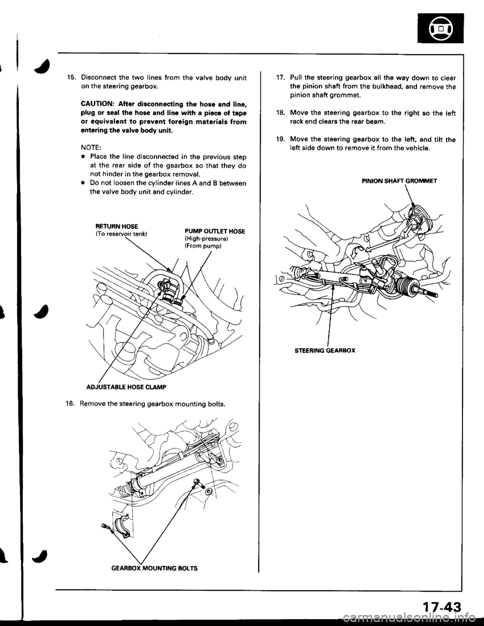
15. Disconnect the two lines from the valve bodv unit
on the steering gearbox.
CAUTION: After disconnscting the hose and line,plug or seal the hose and lino whh I pi6ce ot tape
o. oquivalent to prevont foreign matarials from
6rioring the vslve body unit,
NOTE:
. Place the line disconnected in the previous steD
at the rear side of the gearbox so that they do
not hinder in the gearbox removal.
. Do not loosen the cylinder lines A and B between
the valve body unit 8nd cvlinoer.
ADJUSTABLE HOSE CLAMP
Remove the steering gearbox mounting bolts.16.
\
RETURN HOSE
GEARBOX MOUNTING BOTTS
17-43
't7.
19.
Pull the steering gearbox all the way down to clear
the pinion shaft from the bulkhead, and remove thepinion shaft grommet.
Move the steering gearbox to the right so th€ left
rack end clears the rear beam.
Mov€ the steering gearbox to the loft, and tilt theleft side down to remove it from the vehicle.
PINION SHAFT GBOMMET
STEERING GEARBOX
Page 706 of 1680
Power Steering Gearbox
Reassembly (cont'dl
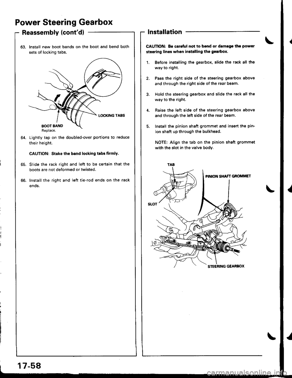
63. Install new boot bands on the boot and bend both
sets of locking tabs.
Lightly tap on the doubled-over portions to reduce
their height.
CAUTION: Stake ihe bsnd locking tabs tirmly.
Slide the rack right and ieft to be certain that the
boots are not deformed or twisted.
Install the right and left tie-rod ends on the rack
enos.
64.
lnstallation
CAUTION: Bo caretul not to bond or damrge the powcr
steering lines when in3t8lling the grlrbox.
1. Before installing the gearbox, slide the rack all the
way to right.
2, Pass the right side of the stsering gearbox above
and through the right side of the rear beam.
3. Hold the steering gearbox and slide the rack 8ll the
way to the right.
4. Rsise the left side of the steering gearbox above
and through the left side of the rear beam.
5. Install the pinion shaft grommet and insert the pin-
ion shaft up through the bulkhesd.
NOTE: Align the tab on the pinion shaft grommet
with the slot in the valve bodY.
oo.
tAa
17-58
Page 708 of 1680
Power Steering Gearbox
Installation (cont'dl
11. Install the steering joint cover with the clamps and
clips.
lnstall the rear beam brace rod and return line
clamp on the rear beam.
NOTE: lnstall the rear beam brace toward the
return line clamp.
12.
CLIP
38 N.m 13.9 kgl'm,28 lbf tl)
17-60
13. Install the three way catalytic converter with the
new gaskets and new self-locking nuts, and connect
the secondary heated oxygen sensor (HO2S) con-
nector.
SECONOARYHEATED OXYGEN SENSOR CONNECTOR
22 N.m {2.2 kgf.m, 16lbIft)
Connect the shift linkage (M/T model: see section
13, A,,/T model; see section 14).
Thread the right and left tie-rod ends onto the rack
an equal number of turns.
14.
Page 942 of 1680
Carpet
Replacement (cont'd)
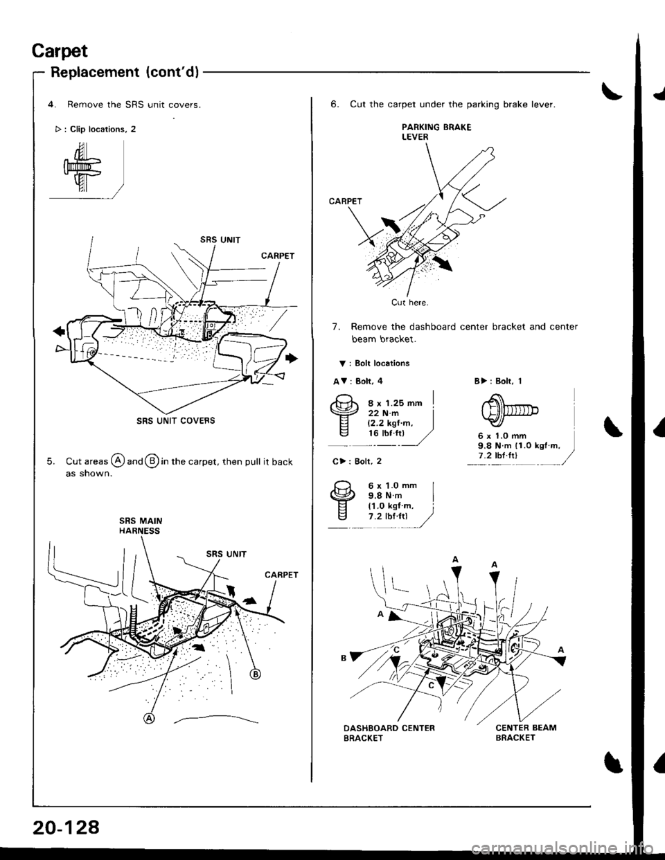
4. Remove the SRS unit covers.
> : Clip locations, 2
SRS UNIT COVEBS
5. Cut areas @ and @ in the carpet, then pull itback
as shown.
20-128
6. Cut the carpet under the parking brake lever.
PARKING ERAKELEVER
CARPET
7. Remove the dashboard center bracket and center
beam bracket.
V i Bolt locations
AV: Bolt, 4
ex r.zsmm I
B>: Bolt, 1
6 x 1.0 mm9.8 N m 11.0 kgt m.7 .2 thl.trl
22 N.m I12.2 kgt'm, Itu-:u ,/
C>: Boll, 2
6 x 1.O mm I9.8Nm I('l.0 kgl m, i7 .2 tbt4tl /,/
Cut here.
Page 955 of 1680
Bumpers
Front Bumper Replacement
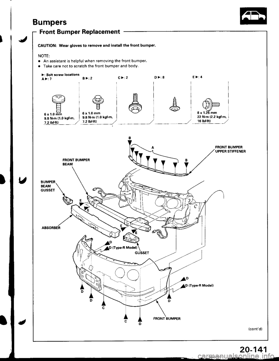
CAUTION: Wear gloves to remove and install the tront bumper.
NOTE:
. An assistant is helpful when removing the front bumper.
. Take care not to scratch the front bumper and body.
>: Boh screw locetion3E>:4A>:7B >12C> 12D>:8
6x1.0mm i9.8 N.m (1.0 kgf m, I
?.2 rbl.ftl J
6x1.0mm9.8 N'm {1.0 kgf'm,8 x 1.25 mm22 N.n l'2.2 kgl-m,
7.2bftrl ._.--r,/-------_,/!6tbt;1t _ _/
BUMPERBEAMGUSSET
\
g
GUSSET
{Type-R Model}
ID
FRONT BUMP€R
{cont'd)