Page 85 of 1680
Valves, Valve Springs and Valve Seals
Removal (cont'dl
3. Installthe special tool as shown
VALVE GUIDE SEAL REMOVERCOMMERCIALLY AVAILABLELISLE P/N 57900 or KD3350
.i
'iii
tI
i{
lf
4. Remove the valve seal.
v,l
lntaks valve Dimsnsions
A Standard (Newl: 30.90 - 31.10 mm
B Standard (New):
C Standard {New):
C Sorvice Limit:
D Standard (Now):
D Service Limil:
B Standard (New):
C Standard {N6w}:
C Service Limit:
D Standsrd lNow):
D Servic€ Limit:
11-217 - 1.221inl
103.80 - 104.10 mm
14.087 - 4.098 in)
6.580 - 6.590 mm(0.2591 - 0.2594 in)
6.55 mm (0.258 inl
1.35 - 1.65 mm(0.053 - 0.065 in)'1.15 mm (0.0'15 inl
Exhaust Vslve Dimonsions
A Standard lNew): 27.90 - 28.10 mm\
11.098 - 1.106 in)
1O4.OO - 10,1.30 mm
l,[.09/t - 4.106 in)
5.550 - 6.560 mm
10.2579 - 0.2583 in)
6.52 mm (0.257 inl
1.65 - 1.95 mm
(0.065 - 0.077 in)
1.45 mm (0.057 in)
Page 86 of 1680
\-
Installation Sequence
Exhaust and intake valve seals are NOT interchanoeable.
NOTE: Place the end of valvespring with closely wound coilstoward the cylinder head.
EXHAUST VALVE SEALIBLACK SPRING}Replace.
@A..'..--uoruEKEEPER'
9-...-'PRTNGREYATNER
VALVE SPRING
INTAKE VALVE SEALIWHITE SPRINGIReplace.
I
PLASTIC MALLET
VALVE GUIDESEAL INSTALLER07GAD - PH70100
,@.t.'( (Sz) I<-- SPRING
V SEAT
NOTE: lnstall the valve spring seatsbefore installing the valve seals.
6-25
Page 87 of 1680

Valve Installation'alve Inslallauon -
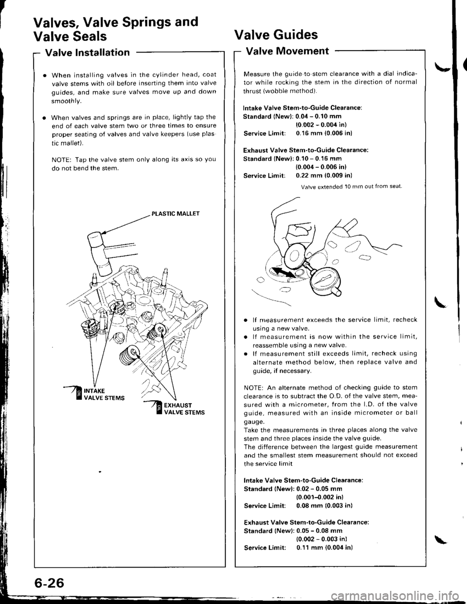
When installing valves in the cylinder head, coat
valve stems with oil belore inserting them into valve
guides, and make sure valves move up and down
smoothly.
When valves and springs are in place, lightly tap the
end of each valve stem two or three times to ensure
proper seating of valves and valve keepers (use plas
tic mallet).
NOTE: Tap the valve stem only along lts axrs so you
do not bend the stem.
PLASTIC MALLET
Valves, Valve Springs and
Valve SealsValve
Valve
Guides
Movement
\-
L
valve tvtovemenr -
Measure the guide to stem clearance with a dial indica-
tor while rocking the stem in the direction of normal
thrust {wobble method).
lntake Valve Stem-to-Guide Clearance:
Standard {Newlr 0.04 - 0.10 mm
10.002 - 0.004 in)
Service Limit: 0.16 mm {0.005 in)
Exhaust Valve Stem-to-Guide Clearance:
Standard {New}: 0.10 - 0.16 mm
(0.004 - 0.006 inl
Service Limit: 0.22 mm (0.009 in)
Valve extended 10 mm out from seat
lf measurement exceeds the service limit, recheck
usrng a new valve.
lf measurement is now within the service limit,
reassemble using a new valve.
lf measurement still exceeds limit, recheck using
alternate method below, then replace valve and
guide, if necessary.
NOTEr An alternate method of checking guide to stem
clearance is to subtract the O.D. of the valve stem, mea-
sured with a micrometer, from the l.D. o{ the valve
guide, measured with an inside micrometer or ball
ga uge.
Take the measurements in three places along the valve
stem and three places inside the valve guide.
The diiference between the largest guide measurement
and the smallest stem measurement should not exceed
the service limit
lntake Valve Stem-to-Guide Clearance:
Standard (Newl: 0.02 - 0.05 mm
10.001-{.002 inl
Service Limit: 0,08 mm (0.003 in)
Exhaust Valve Stem-to-Guide Clearance:
Standard (New): 0.05 - 0.08 mm
{0.002 - 0.003 in)
Service Limit: 0.11 mm {0.004 in)\
Page 88 of 1680

\,
Replacement
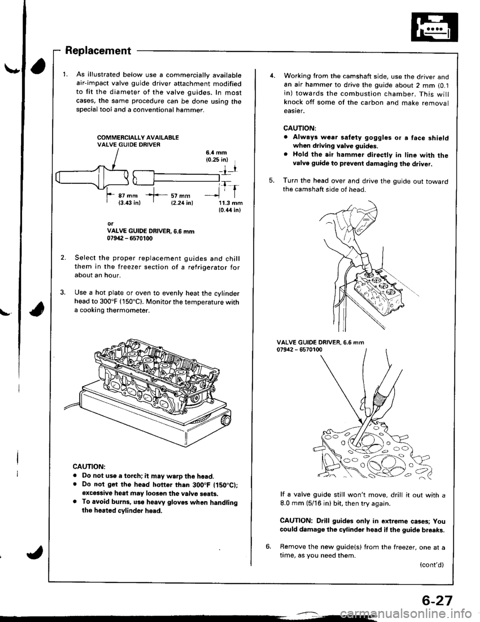
1. As illustrated below use a commercially available
air-impact valve guide driver attachment modified
to fit the diameter of the valve guides, In most
cases, the same procedure can be done using thespecial tool and a conventional hammer.
6.il mm{0.25 inl
rr
*f-::rtl1-r87 mm{3.43 in)11.3 mm10.44 inl
orVALVE GUIDE DBIVER, 6.6 mm07942 - 6570100
Select the proper replacement guides and chillthem in the freezer section of a refrigerator forabout an hour.
Use a hot plate or oven to evenly heat the cylinderhead to 300"F (150"C). Monitor the temperature witha cooking thermometer.
CAUTION:
. Do not use a torch; it may warp the hoad.. Do not ger tho head hotter than 300.F ltS0"C);exces3ive heat may loo3en the valvo seats.. To avoid burns, uss heaw gloves when handlingthe heat€d cylinder head.
12.21inl
6-27
Working trom the camshaft side, use the driver and8n air hammer to drive the guide about 2 mm (0.1
in) towards the combustion chamber. This willknock off some of the carbon and make removaleaster.
CAUTION:
. Always wear safety goggles or a face shieldwhen driving valve guides.
. Hold the air hammer direcfly in line with thevalve guide to prevent damaging the driver.
Turn the head over and drive the guide out towardthe camshaft side of head.
5.
VALVE GUIDE DRIVER.079i12 - 65701006.6 mm
lf a valve guide still won't move. drill it out with a
8.0 mm (5/16 in) bit, then try again.
CAUTION: Drill guides only in extreme cases; You
could damage the cylinder head it the guide breaks.
6. Remove the new guide{s) from the freezer, one at atime, as you need them.
{cont'd)
OO
'o c,
Page 90 of 1680

\
Valve Seats
Reconditioning
ACTUALSEATINGSURFACE
VALVESEAT
Renew the valve seats in the cylinder head using avalve seat cutter.
NOTE: lf guides are worn (see page 6-26), replace
them {see page 6-27) before cutting the valve seats.
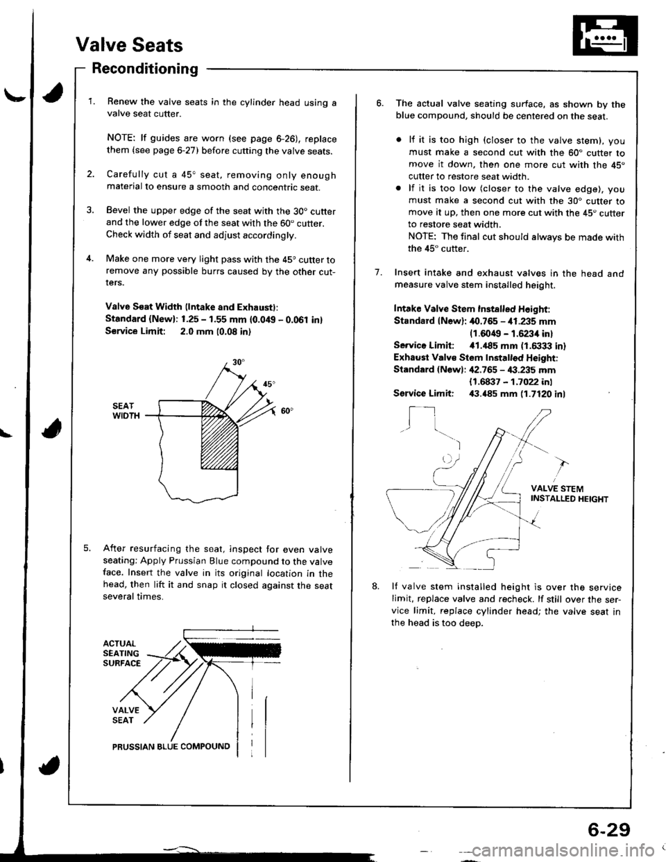
Carefully cut a 45" seat, removing only enoughmaterial to ensure a smooth and concentric seat.
Bevel the upper edge of the seat with the 30. cutterand the lower edge of the seat with the 60. cutter.Check width of seat and adjust accordingly.
Make one more very light pass with the 45o cutter toremove any possible burrs caused by the other cut-rers.
V8lv6 S€at Width (lntake and Exhaustl:
Standard {New}: 1.25 - 1.55 mm {0.0/t{, - 0.061 in}
S€rvice Limit: 2.0 mm 10.08 in)
After resurfacing the seat, inspect for even valveseating: Apply Prussian Blue compound to the valveface. Insert the valve in its original location in thehead, then lift it and snap it closed against the seatseveral times.
PRUSSIAN BLUE COMPOUNO
6-29
o.The actual valve seating surface, as shown by theblue compound, should be centered on the seat.
lf it is too high (closer to the valve stem), you
must make a second cut with the 60" cutter tomove it down, then one more cut with the 45"
cutter to restore seat width.
lf it is too low (closer to the valve edge), you
must make a second cut with the 30. cutter tomove at up, then one more cut with the 45. cutterto restore seat width.
NOTE: The final cut should always be made with
the 45" cutter.
Insert intake and exhaust valves in the head andmeasure valve stem installed height.
Intake Valve Stem Inst8lled Height:
Standard lN6wl: 40.765 - i11.235 mm(1.6049 - 1.6234 in)
Servico Limiti i01.,|85 mm (1.6333 in)
Exhaust Valv€ Stem Installed Height:
Standard {Newl: ,[2.765 - 4:1.235 mm
1.
{1.68i}7 - 1.7022 inl,(1.485 mm 11.7120 inlService Limit:
I_1I
VALVE STEMINSTAI-LED HEIGHT
8.lf valve stem installed height is over the servicelimit, replace valve and recheck. lf still over the ser-vice limit, replace cylinder head; the valve seat in
the head is too deep.
Page 92 of 1680

\-
L
Install the intake manifold and tighten the nuts in acflsscross pattern in 2 or 3 steps. beginning with theinner nuts.
CAUTION: Check lor folds or scratches on the sur-face ol the gasket. Replace with a new gasket ildamaged.GASKETReplace.
INTAKEMANIFOLD
4. Tighten the intake manifold bracket bolts.5. Install the exhaust maniiold and tighten the newself-locking nuts in a crisscross pattern in 2 or 3steps, beginning with the inner nuts.. Use new self-locking nuts.
EXHAUSTMANIFOLD
GASKETReplace.
4
10 x 1.25 mm 8 x 1.25 mm4,{ N.rn 14.5 kgf.m, 24 N.m {2.4 kgtm,33 tbf.ftl '17 tbf.ft)
SELF.LOCKING NUT8 x 1.25 mm31 N.m (3.2 kgt m,23 lbf.ft)Replace.1 .25 mmN.m {2.4 kg{.m,rbrftt
\q
8x2417
",', r, ^-'-"-!,1,,,';-21N.m l2.1kglm, 23 N.m (2.3 ksf.m,17lbf.ftl 17 tbf.ftr
6-31
CAUTION:
. Make sure that the keyways on the camshafts aretacing up and No. 1 piston is at top dead cenier
tTDCt.. Replacethe rocker arms in their original positions.
6. Place the rocker arms on the pivot bolts and thevalve stems.
7.
8.
Install the camshafts, then install the camshaft sealswith the open side (spring) facing in.
Apply liquid gasket to the head mating surfaces otthe No. 1 and No. 6 camshaft holders, then installthem, along with No.2,3, 4, and 5.
NOTE:
. "l" or "E' marks are stamped on the camshaftholders.
. Do not apply oil to the holder mating surface ofcamshaft seals.. Apply liquid gasket to the shaded areas.. The arrows marked on the camshaft holdersshould point to the timing belt.. Clean and dry the cylinder head mating surfacesbefore applying liquid gasket.
INTAKE CAMSHAFT HOLDERS
No.6 No.5No.4No.3 No.2 No. 1
{cont'd)
Page 93 of 1680

Cylinder Head
Installation (cont'dl
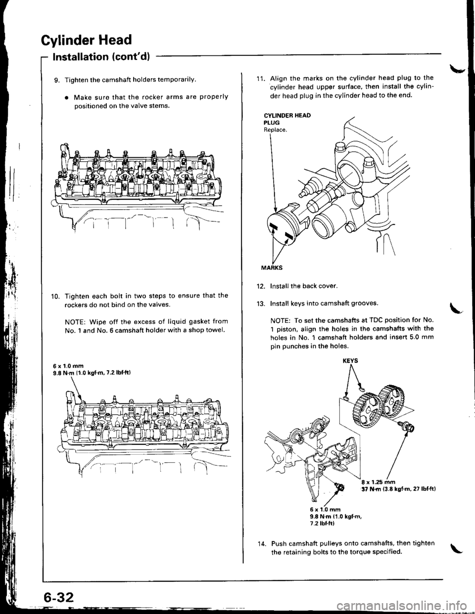
9, Tighten the camshaft holders temporarily.
a Make sure that the rocker arms are properly
positioned on the valve stems
10. Tighten each bolt in two steps to ensure that the
rockers do not bind on the valves.
NOTE: wipe off the excess of liquid gasket from
No. 1 and No. 6 camshaft holder with a shop towel
6x1.0mm9,8 N.m 11.0 kgf m, 7.2 lbt'ftl
\-
11. Align the marks on the cylinder head plug to the
cylinder head upper surface, then install the cylin-
der head plug in the cylinder head to the end.
CYLINDEB HEADPLUGReplace.
13.
lnstall the back cover.
Install keys into camshaft grooves.
NOTE: To set the camshafts at TDC position for No.
1 piston, align the holes in the camshafts with the
holes in No. 1 camshsft holders snd insert 5.0 mm
pin punches in the holes.
8 x 1.25 mmt7 N.|rl {3.8 kst.m,27 lbf.ftl
6x1.0mm9.8 N.m {1.0 kgt m.7.2 tbr.ft)
Push camshaft pulleys onto camshafts, then tighten
the retaining bolts to the torque specified.
KEYS
14.
Page 94 of 1680
15.
16.
17.
Install the timing belt (see page 6-12).
Adjust the valve clearance (see page 6-3).
lnstall the rubber seal in the groove of the cylinderhead cover. Seat the seal in the recesses for thecamshaft first, then work it into the groove aroundthe outside edges.
NOTE:
. Before installing the rubber seal, thoroughlyclean the seal and the groove.
. When installing, make sure the seal is seatedsecurely in the corners of the recesses with nogap.
RUEBER SEAL
18.Apply liquid gasket to the rubber seal at the eightcorners of the recesses.
NOTE:
. Use liquid gasket, Part No. 08718 - OO01 or 08718- 0003.
. Check that the mating surfaces are clean and drybefore applying liquid gasket.. Do not installthe parts if 5 minutes or more naveelapsed since applying liquid gasket. Instead,reapply liquid gasket after removing old residue.. After assembly, wait at least 30 minutes beforefilling the engine with oil.
Apply liquid gasket tothe shaded areas.
(cont'd)
6-33