Page 1465 of 1807

- SFI (2JZ-GTE)FUEL PUMP
SF-5
1331 Author�: Date�:
1997")
Q08242
TOYOTA Hand-Held Tester
DLC3
P11446Fuel Inlet Hose
P12558
Fuel Inlet
Hose
SF0GH-01
Z13307
Fuel Inlet HoseSST
Gasket
SSTSST
Gasket(Union)
- SFI (2JZ-GTE)FUEL PUMP
SF-5
1331 Author�: Date�:
1997 SUPRA (RM502U)
FUEL PUMP
ON-VEHICLE INSPECTION
1. CHECK FUEL PUMP OPERATION
(a) Connect the TOYOTA hand-held tester to the DLC3.
(b) Turn the ignition switch ON and TOYOTA hand-held tes-
ter main switch ON.
NOTICE:
Do not start the engine.
(c) Select the ACTIVE TEST mode on the TOYOTA hand-
held tester.
(d) Please refer to the TOYOTA hand-held tester operator's
manual for further details.
(e) If you have no TOYOTA hand-held tester, connect the
positive (+) and negative (-) leads from the battery to the
fuel pump connector.
(See step 8)
(f) Check that there is pressure in the fuel inlet hose from the
fuel filter.
HINT:
If there is fuel pressure, you will hear the sound of fuel flowing.
If there is no pressure, check the following parts:
�Fuses
�EFI No.2 relay
�Fuel pump
�ECM
�Wiring connections
(g) Turn the ignition switch to LOCK.
(h) Disconnect the TOYOTA hand- held tester from the
DLC3.
2. CHECK FUEL PRESSURE
(a) Check the battery voltage is above 12 V.
(b) Disconnect the negative (-) terminal cable from the bat-
tery.
(c) Remove the union bolt and 2 gaskets, disconnect the fuel
inlet hose from the fuel filter.
CAUTION:
�Put a suitable container or shop towel under the fuel
filter.
�Slowly loosen the union bolt.
(d) Install the fuel inlet hose and SST (pressure gauge) to the
fuel filter with the 3 gaskets and SST (union bolt).
SST 09268-45012
Torque: 29 N´m (300 kgf´cm, 22 ft´lbf)
(e) Wipe off any splattered gasoline.
Page 1466 of 1807
FUEL PUMP
1332 Author�: Date�:
1997 SUPRA (RM502U)
(f) Connect the TOYOTA hand-held tester to the DLC3.
(See step 1 in")
Q08242
TOYOTA Hand-Held Tester
DLC3
P12563
Disconnect
Plug SF-6
- SFI (2JZ-GTE)FUEL PUMP
1332 Author�: Date�:
1997 SUPRA (RM502U)
(f) Connect the TOYOTA hand-held tester to the DLC3.
(See step 1 in check fuel pump operation (a) to (e).)
(g) Reconnect the negative (-) terminal cable to the battery.
(h) Turn the ignition switch ON.
(i) Measure the fuel pressure.
Fuel pressure:
226 - 275 kPa (2.3 - 2.8 kgf/cm
2, 33 - 40 psi)
If pressure is high, replace the fuel pressure regulator.
If pressure is low, check the following parts:
(1) Fuel hoses and connections
(2) Fuel pump
(3) Fuel filter
(4) Fuel pressure regulator
(j) Remove the TOYOTA hand-held tester from the
DLC3.
(k) Start the engine.
(l) Disconnect the vacuum sensing hose from the fuel pres-
sure regulator, and plug the hose end.
(m) Measure the fuel pressure at idle.
Fuel pressure:
226 - 275 kPa (2.3 - 2.8 kgf/cm
2, 33 - 40 psi)
(n) Reconnect the vacuum sensing hose to the fuel pressure
regulator.
(o) Measure the fuel pressure at idle.
Fuel pressure:
167 - 216 kPa (1.7 - 2.2 kgf/cm
2, 24 - 31 psi)
If pressure is not as specified, check the vacuum sensing hose
and fuel pressure regulator.
(p) Stop the engine.
(q) Check that the fuel pressure remains as specified for 5
minutes after the engine has stopped.
Fuel pressure:
147 kPa (1.5 kgf/cm
2, 21 psi) or more
If pressure is not as specified, check the fuel pump, pressure
regulator and/or injectors.
(r) After checking fuel pressure, disconnect the negative (-)
terminal cable from the battery and carefully remove the
SST to prevent gasoline from splashing.
SST 09268-45012
(s) Reinstall the fuel inlet hose to the fuel filter with 2 new gas-
kets and the union bolt.
Torque: 29 N´m (300 kgf´cm, 22 ft´lbf)
(t) Reconnect the negative (-) terminal cable to the battery.
(u) Check for fuel leaks.
3. TAKE OUT FLOOR CARPET
4. REMOVE SPARE WHEEL COVER
5. REMOVE SPARE WHEEL
6. REMOVE SERVICE HOLE COVER
7. DISCONNECT FUEL PUMP & SENDER GAUGE CON-
NECTOR
Page 1469 of 1807
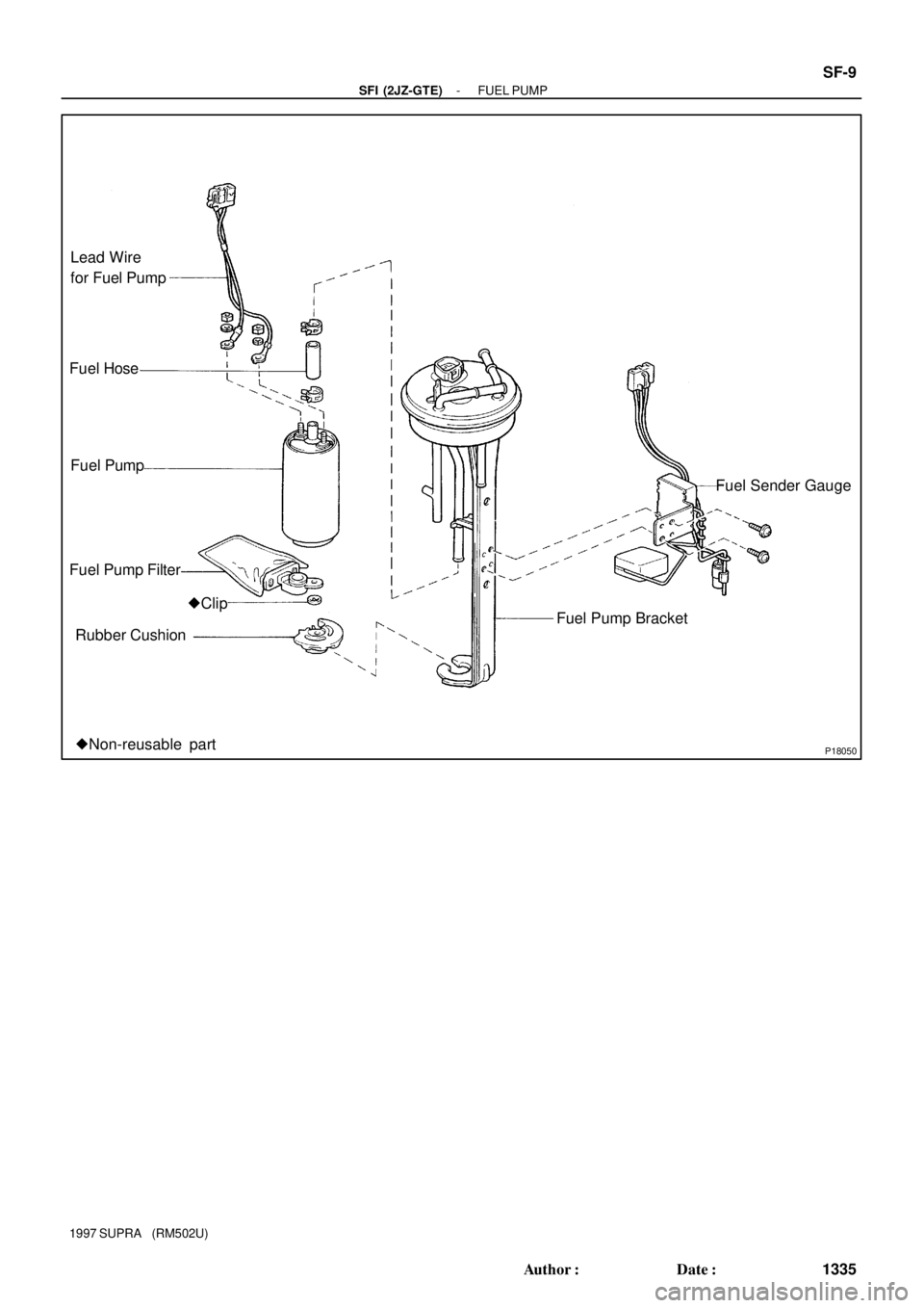
P18050
Fuel Pump FilterFuel Sender Gauge Fuel Hose Lead Wire
for Fuel Pump
Fuel Pump
Rubber Cushion�Clip
Fuel Pump Bracket
�Non-reusable part
- SFI (2JZ-GTE)FUEL PUMP
SF-9
1335 Author�: Date�:
1997 SUPRA (RM502U)
Page 1471 of 1807
P11481
SF0GK-01
P11970
P11482Pull
P11971
Clip
- SFI (2JZ-GTE)FUEL PUMP
SF-1 1
1337 Author�: Date�:
1997 SUPRA (RM502U)
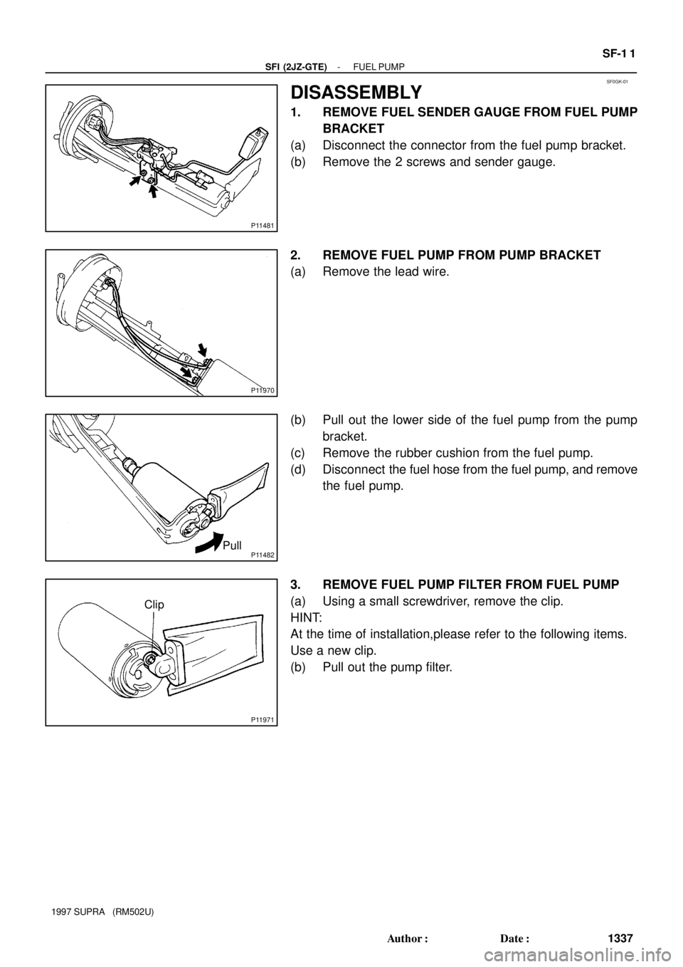
DISASSEMBLY
1. REMOVE FUEL SENDER GAUGE FROM FUEL PUMP
BRACKET
(a) Disconnect the connector from the fuel pump bracket.
(b) Remove the 2 screws and sender gauge.
2. REMOVE FUEL PUMP FROM PUMP BRACKET
(a) Remove the lead wire.
(b) Pull out the lower side of the fuel pump from the pump
bracket.
(c) Remove the rubber cushion from the fuel pump.
(d) Disconnect the fuel hose from the fuel pump, and remove
the fuel pump.
3. REMOVE FUEL PUMP FILTER FROM FUEL PUMP
(a) Using a small screwdriver, remove the clip.
HINT:
At the time of installation,please refer to the following items.
Use a new clip.
(b) Pull out the pump filter.
Page 1484 of 1807
SF0GT-02
P12826
Injector
Fuel Pressure Regulator
SST
(Union)
Fuel Return Hose
(On Vehicle)SST
(Union) Fuel Filter
(On Vehicle)SST
(Hose)SST
Union Delivery Pipe
P11302
Insulator
P12558
Fuel Inlet
Hose
- SFI (2JZ-GTE)INJECTOR
SF-25
1351 Author�: Date�:
1997 SUPRA (RM502U)
INSPECTION
1. INSPECT INJECTOR INJECTION
CAUTION:
Keep injector clear of sparks during the test.
(a) Install the insulator to each injector.
(b) Install the 3 injector holders with the 6 bolts.
Torque: 7.8 N´m (80 kgf´cm, 69 in.´lbf)
(c) Remove the union bolt and 2 gaskets, and disconnect the
fuel inlet hose from the fuel filter outlet.
Page 1485 of 1807
Z13305
SST
(Union)SST
(Hose)Union
Bolt
Gasket
P12559Fuel Return Hose
Z13308
Fuel Return
Hose
SST
(Union)
Gasket
Union
Bolt
Z13304
SST (Union) Gasket
Union
Bolt
SST (Hose) SF-26
- SFI (2JZ-GTE)INJECTOR
1352 Author�: Date�:
1997 SUPRA (RM502U)
(d) Connect SST (hose) to the fuel filter outlet with SST
(union), the 2 gaskets and union bolt.
SST 09268-41046 (90405-09015)
Torque: 29 N´m (300 kgf´cm, 22 ft´lbf)
(e) Disconnect the fuel return hose from the fuel return pipe.
(f) Connect the fuel return hose to the fuel outlet of the pres-
sure regulator on the delivery pipe with SST (union), the
2 gaskets and union bolt.
SST 09268-41046 (09268-41071)
(g) Connect SST (hose) to the fuel inlet of the delivery pipe
with SST (union), the 2 gaskets and union bolt.
SST 09268-41046 (90405-09015)
(h) Put the injector into the graduated cylinder.
Page 1486 of 1807

Connect
P12549
- SFI (2JZ-GTE)INJECTOR
SF-27
1353 Author�: Date�:
1997 SUPRA (RM502U)
(i) Connect the TOYOTA hand-held tester to the DLC3.
(j)")
Q08242
TOYOTA Hand-Held Tester
DLC3
P12548
SST (Wire)
Connect
P12549
- SFI (2JZ-GTE)INJECTOR
SF-27
1353 Author�: Date�:
1997 SUPRA (RM502U)
(i) Connect the TOYOTA hand-held tester to the DLC3.
(j) Turn the ignition switch ON and TOYOTA hand-held tes-
ter main switch ON.
NOTICE:
Do not start the engine.
(k) Select the active test mode on the TOYOTA hand-held
tester.
(l) Please refer to the TOYOTA hand-held tester operator's
manual for further details.
(m) If you have no TOYOTA hand-held tester, connect the
positive (+) and negative (-) leads from the battery to the
fuel pump connector.
(n) Connect SST (wire) to the injector and battery for 15 se-
conds, and measure the injection volume with a gra-
duated cylinder. Test each injector 2 or 3 times.
SST 09842-30060
Injection volume:
111 - 141 cm
3 (6.8 - 8.6 cu in.) per 15 sec.
Difference between each injector:
10 cm
3 (0.6 cu in.) or less
If the injection volume is not as specified, replace the injector.
2. INSPECT LEAKAGE
(a) In the condition above, disconnect the tester probes of
SST (wire) from the battery and check the fuel leakage
from the injector.
SST 09842-30060
Fuel drop:
One drop or less per minutes
(b) Turn the ignition switch to LOCK.
(c) Disconnect the negative (-) terminal cable from the bat-
tery.
(d) Remove the SST.
SST 09268-41046
(e) Reconnect the fuel inlet hose to the fuel filter with 2 new
gaskets and the union bolt.
Torque: 29 N´m (300 kgf´cm, 22 ft´lbf)
(f) Reconnect the fuel return hose to the fuel return pipe.
(g) Remove the 6 bolts, 3 injector holders and 6 insulators.
(h) Disconnect the TOYOTA hand- held tester from the
DLC3.
Page 1514 of 1807
SF0HL-01
P11340
Ohmmeter
Continuity
P11341
Ohmmeter
No Continuity
P11342
Air
E
G
P11343
Air
E
Filter Battery
- SFI (2JZ-GTE)VSV FOR FUEL PRESSURE CONTROL
SF-59
1385 Author�: Date�:
1997 SUPRA (RM502U)
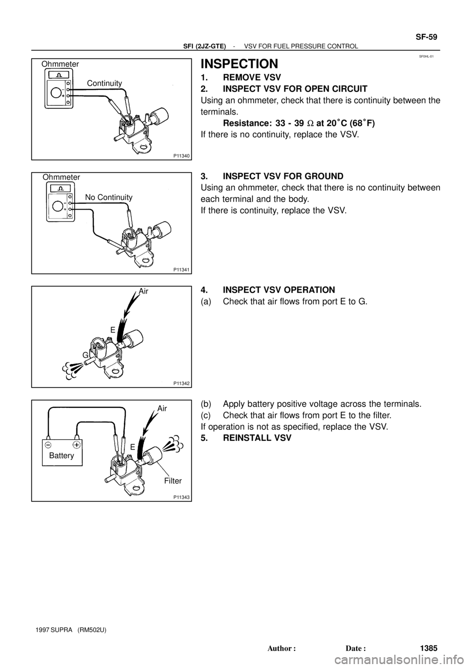
INSPECTION
1. REMOVE VSV
2. INSPECT VSV FOR OPEN CIRCUIT
Using an ohmmeter, check that there is continuity between the
terminals.
Resistance: 33 - 39 W at 20°C (68°F)
If there is no continuity, replace the VSV.
3. INSPECT VSV FOR GROUND
Using an ohmmeter, check that there is no continuity between
each terminal and the body.
If there is continuity, replace the VSV.
4. INSPECT VSV OPERATION
(a) Check that air flows from port E to G.
(b) Apply battery positive voltage across the terminals.
(c) Check that air flows from port E to the filter.
If operation is not as specified, replace the VSV.
5. REINSTALL VSV

Fuel Return Hose
(On Vehicle)SST
(Union) Fuel Filter
(On Vehicle)SST
(Hose)SST
Union Delivery Pipe
P11302
Insulator
P12558
Fuel Inlet
Hose")
SST
(Hose)Union
Bolt
Gasket
P12559Fuel Return Hose
Z13308
Fuel Return
Hose
SST
(Union)
Gasket
Union
Bolt
Z13304
SST (Union) Gasket
Union
Bolt
SST (Hose) SF-26
- SFI (2JZ-GTE)INJECTOR")