Page 270 of 3342
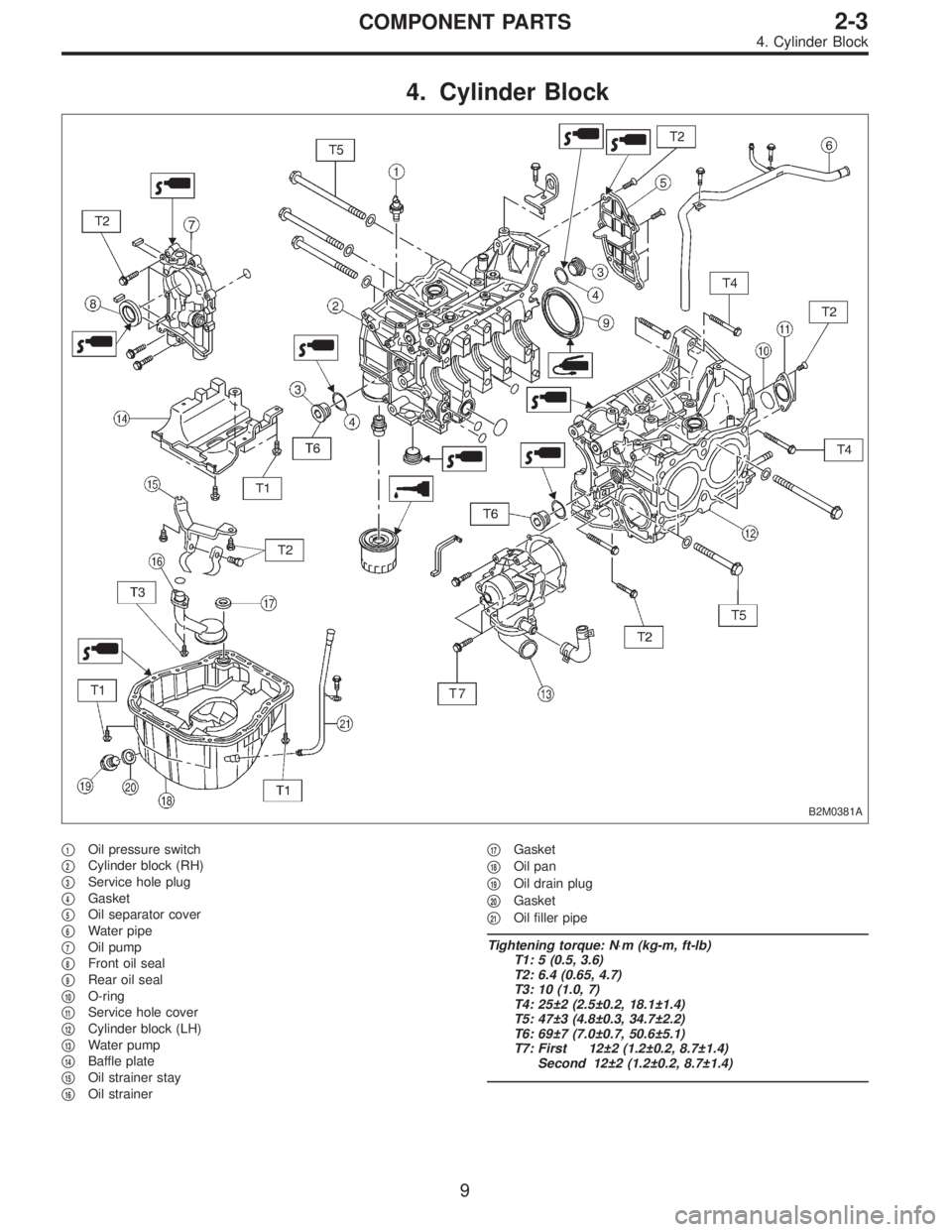
4. Cylinder Block
B2M0381A
�1Oil pressure switch
�
2Cylinder block (RH)
�
3Service hole plug
�
4Gasket
�
5Oil separator cover
�
6Water pipe
�
7Oil pump
�
8Front oil seal
�
9Rear oil seal
�
10O-ring
�
11Service hole cover
�
12Cylinder block (LH)
�
13Water pump
�
14Baffle plate
�
15Oil strainer stay
�
16Oil strainer�
17Gasket
�
18Oil pan
�
19Oil drain plug
�
20Gasket
�
21Oil filler pipe
Tightening torque: N⋅m (kg-m, ft-lb)
T1: 5 (0.5, 3.6)
T2: 6.4 (0.65, 4.7)
T3: 10 (1.0, 7)
T4: 25±2 (2.5±0.2, 18.1±1.4)
T5: 47±3 (4.8±0.3, 34.7±2.2)
T6: 69±7 (7.0±0.7, 50.6±5.1)
T7: First 12±2 (1.2±0.2, 8.7±1.4)
Second 12±2 (1.2±0.2, 8.7±1.4)
9
2-3COMPONENT PARTS
4. Cylinder Block
Page 315 of 3342
G2M0163
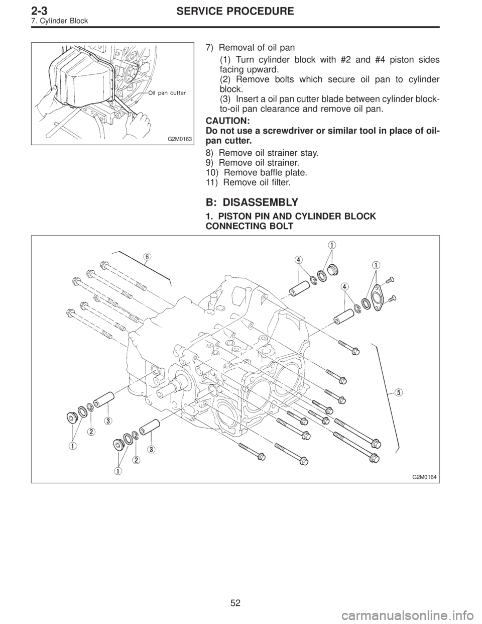
7) Removal of oil pan
(1) Turn cylinder block with #2 and #4 piston sides
facing upward.
(2) Remove bolts which secure oil pan to cylinder
block.
(3) Insert a oil pan cutter blade between cylinder block-
to-oil pan clearance and remove oil pan.
CAUTION:
Do not use a screwdriver or similar tool in place of oil-
pan cutter.
8) Remove oil strainer stay.
9) Remove oil strainer.
10) Remove baffle plate.
11) Remove oil filter.
B: DISASSEMBLY
1. PISTON PIN AND CYLINDER BLOCK
CONNECTING BOLT
G2M0164
52
2-3SERVICE PROCEDURE
7. Cylinder Block
Page 318 of 3342
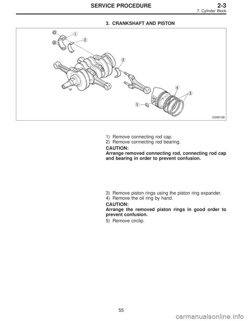
3. CRANKSHAFT AND PISTON
G2M0168
1) Remove connecting rod cap.
2) Remove connecting rod bearing.
CAUTION:
Arrange removed connecting rod, connecting rod cap
and bearing in order to prevent confusion.
3) Remove piston rings using the piston ring expander.
4) Remove the oil ring by hand.
CAUTION:
Arrange the removed piston rings in good order to
prevent confusion.
5) Remove circlip.
55
2-3SERVICE PROCEDURE
7. Cylinder Block
Page 329 of 3342
B2M1211A
4) Installation of piston rings and oil ring
(1) Install oil ring spacer, upper rail and lower rail in this
order by hand. Then install second ring and top ring
with a piston ring expander.
(2) Position the top ring gap at A or B in the Figure.
(3) Position the second ring gap at 180°on the reverse
side for the top ring gap.
B2M1212A
(4) Position the upper rail gap at C or D in the Figure.
(5) Position the expander gap at 180°of the reverse
side for the upper rail gap.
(6) Position the lower rail gap at E or F in the Figure.
CAUTION:
�Ensure ring gaps do not face the same direction.
�Ensure ring gaps are not within the piston skirt area.
G2M0183
5) Install circlip.
Install circlips in piston holes located opposite service
holes in cylinder block, when positioning all pistons in the
corresponding cylinders.
CAUTION:
Use new circlips.
NOTE:
Piston front mark“�”facer toward front of engine.
66
2-3SERVICE PROCEDURE
7. Cylinder Block
Page 336 of 3342
G2M0084
1) Install baffle plate.
2) Install oil strainer and O-ring
3) Install oil strainer stay.
4) Apply fluid packing to matching surfaces and install oil
pan.
Fluid packing:
THREE BOND 1207C or equivalent
G2M0194
5) Apply fluid packing to matching surfaces and install oil
separator cover.
Fluid packing:
THREE BOND 1215 or equivalent
G2M0161
6) Install flywheel or drive plate.
To lock crankshaft, use ST.
ST 498497100 CRANKSHAFT STOPPER
7) Install housing cover.
G2M0076
8) Installation of oil pump
(1) Discard front oil seal after removal. Replace with a
new one by using ST.
ST 499587100 OIL SEAL INSTALLER
73
2-3SERVICE PROCEDURE
7. Cylinder Block
Page 340 of 3342
TROUBLE
Engine will not start.
Rough idle and engine stall
Low output, hesitation and poor acceleration
Surging
Engine does not return to idle.
Dieseling (Run-on)
After burning in exhaust system
Knocking
Excessive engine oil consumption
Excessive fuel consumption Starter does not turn.
Initial combustion does not occur.
Initial combustion occurs.
Engine stalls after initial combustion.
LUBRICATION SYSTEM
22 3 3�Incorrect oil pressure
2�Loosened oil pump attaching bolts and defective
gasket
2�Defective oil filter seal
2�Defective crankshaft oil seal
32�Defective rocker cover gasket
2�Loosened oil drain plug or defective gasket
2�Loosened oil pan fitting bolts or defective oil pan
COOLING SYSTEM
33221�Overheating
333�Over cooling
OTHERS
113 3�Malfunction of Evaporative Emission Control
System
21�Stuck or damaged throttle valve
322 2�Accelerator cable out of adjustment
77
2-3DIAGNOSTICS
1. Engine Trouble in General
Page 350 of 3342
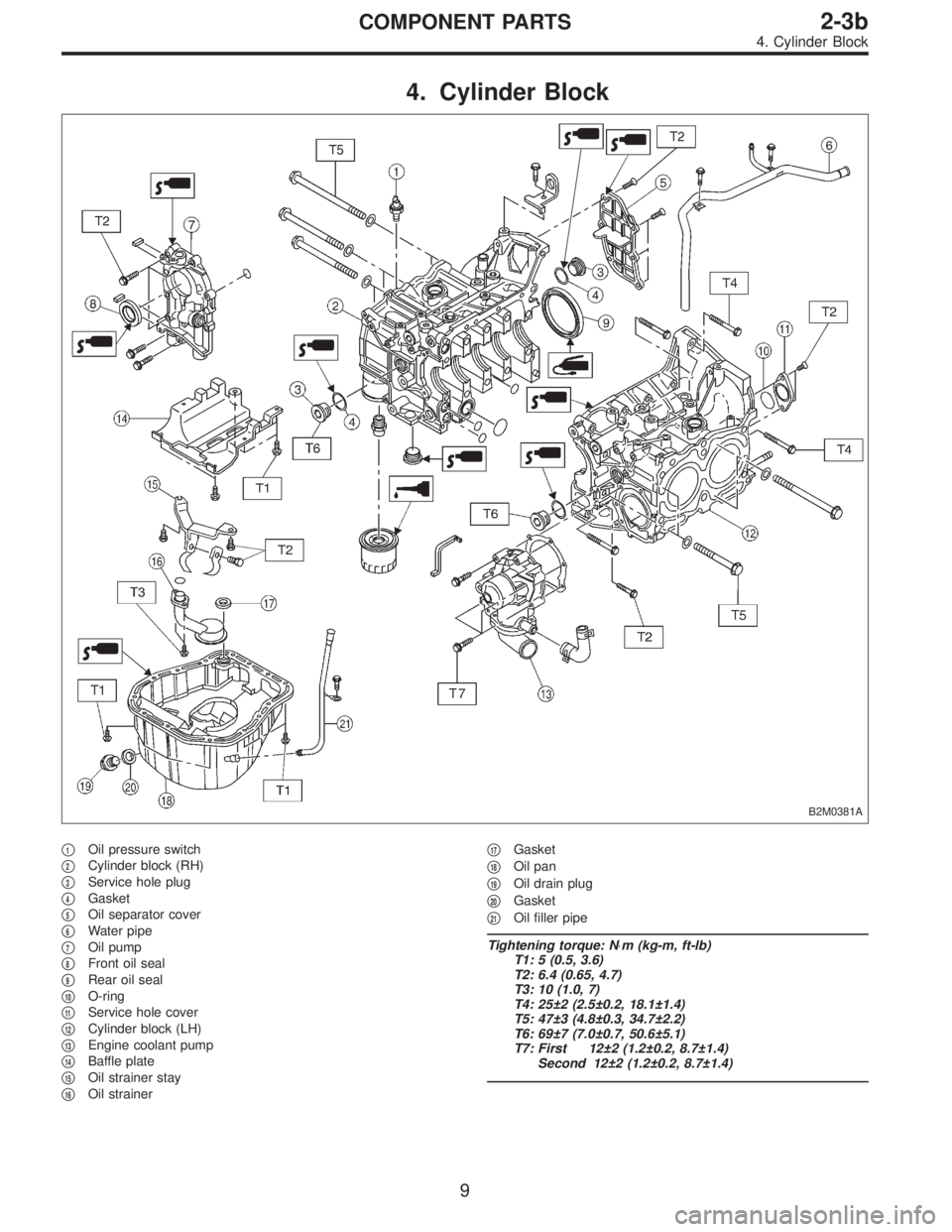
4. Cylinder Block
B2M0381A
�1Oil pressure switch
�
2Cylinder block (RH)
�
3Service hole plug
�
4Gasket
�
5Oil separator cover
�
6Water pipe
�
7Oil pump
�
8Front oil seal
�
9Rear oil seal
�
10O-ring
�
11Service hole cover
�
12Cylinder block (LH)
�
13Engine coolant pump
�
14Baffle plate
�
15Oil strainer stay
�
16Oil strainer�
17Gasket
�
18Oil pan
�
19Oil drain plug
�
20Gasket
�
21Oil filler pipe
Tightening torque: N⋅m (kg-m, ft-lb)
T1: 5 (0.5, 3.6)
T2: 6.4 (0.65, 4.7)
T3: 10 (1.0, 7)
T4: 25±2 (2.5±0.2, 18.1±1.4)
T5: 47±3 (4.8±0.3, 34.7±2.2)
T6: 69±7 (7.0±0.7, 50.6±5.1)
T7: First 12±2 (1.2±0.2, 8.7±1.4)
Second 12±2 (1.2±0.2, 8.7±1.4)
9
2-3bCOMPONENT PARTS
4. Cylinder Block
Page 394 of 3342
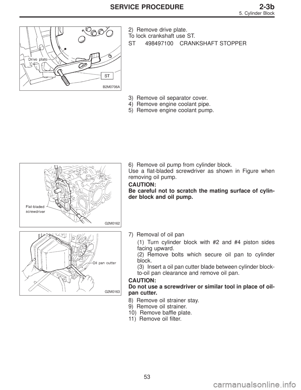
B2M0706A
2) Remove drive plate.
To lock crankshaft use ST.
ST 498497100 CRANKSHAFT STOPPER
3) Remove oil separator cover.
4) Remove engine coolant pipe.
5) Remove engine coolant pump.
G2M0162
6) Remove oil pump from cylinder block.
Use a flat-bladed screwdriver as shown in Figure when
removing oil pump.
CAUTION:
Be careful not to scratch the mating surface of cylin-
der block and oil pump.
G2M0163
7) Removal of oil pan
(1) Turn cylinder block with #2 and #4 piston sides
facing upward.
(2) Remove bolts which secure oil pan to cylinder
block.
(3) Insert a oil pan cutter blade between cylinder block-
to-oil pan clearance and remove oil pan.
CAUTION:
Do not use a screwdriver or similar tool in place of oil-
pan cutter.
8) Remove oil strainer stay.
9) Remove oil strainer.
10) Remove baffle plate.
11) Remove oil filter.
53
2-3bSERVICE PROCEDURE
5. Cylinder Block