Page 2563 of 3342

Function code
Measuring
itemsContents to be monitored Scroll Ref. to 4-4b
Code Abbreviation
FB0 D⋅NEWThe most
recent failures
are displayed.Trouble codes, t")
3. FB MODE (TROUBLE CODES ARE DISPLAYED.)
Function code
Measuring
itemsContents to be monitored Scroll Ref. to 4-4b
Code Abbreviation
FB0 D⋅NEWThe most
recent failures
are displayed.Trouble codes, trouble spots and symptoms for the
most recent failure are displayed.Possible [T10B0]
FB1 D⋅ALLHistorical
troubles are
displayed.Trouble codes, trouble spots and symptoms for all
historical failures are displayed.Possible[T10B0]
4. FC MODE (TROUBLE CODES ARE ERASED.)
Function code
Measuring
itemsContents to be monitored Scroll Ref. to 4-4b
Code Abbreviation
FC0 D⋅CLRTrouble codes
are erased.Function of clearing trouble code stored in memory. Possible[T9K0]
5. FD MODE (SEQUENCE CHECK AND AIR RELEASE
MODE)
Function code
Measuring
itemsContents to be monitored Scroll Ref. to
Code Abbreviation
FD1 A⋅CHKABS
sequence
controlPerform ABS sequence control by operating valve
and pump motor sequentially.Impossible4-4
[W20D0]
FD2 T⋅CHKTCS
sequence
controlPerform TCS sequence control by operating the
valve and pump motor sequentially.Impossible4-4
[W20F0]
FD3 AIRAir bleeding
controlManually operate the valve and pump motor to
bleed air.Impossible4-4
[W19A0]
87
4-4bBRAKES
9. Select Monitor Function Mode
Page 2567 of 3342

LED No. Signal name Display
1Front right inlet solenoid
valveFI
2Front right outlet solenoid
valveRO
3Front left inlet solenoid
valveFI
4Front left outlet solenoid
valveLO
5Traction control solenoid
valve 1T1
6Rear right inlet solenoid
valveRI
7Rear right outlet solenoid
valveRO
8Rear left inlet solenoid
valveRI
9Rear left outlet solenoid
valveLO
10Traction control solenoid
valve 2T2
FI RO FI LO T1
RI RO RI LO T2
1
2345
678910
I: MODE FA1
—ON↔OFF SIGNAL—
Requirement for LED“ON”
LED No. 1 Front right inlet solenoid valve is in function.
LED No. 2 Front right outlet solenoid valve is in function.
LED No. 3 Front left inlet solenoid valve is in function.
LED No. 4 Front left outlet solenoid valve is in function.
LED No. 5 Traction control solenoid valve 1 is in func-
tion.
LED No. 6 Rear right inlet solenoid valve is in function.
LED No. 7 Rear right outlet solenoid valve is in function.
LED No. 8 Rear left inlet solenoid valve is in function.
LED No. 9 Rear left outlet solenoid valve is in function.
LED No. 10 Traction control solenoid valve 2 is in func-
tion.
LED No. Signal name Display
1 ABS warning light AW
2 TCS warning light TW
3 TCS OFF indicator light TO
4TCS operating indicator
lightTI
5——
6 AEC signal EC
7 AEB signal EB
8 AET signal ET
9 EAM signal EM
10 AAT signal AT
AW TW TO TI—
EC EB ET EM AT
1
2345
678910
J: MODE FA2
—ON↔OFF SIGNAL—
Requirement for LED“ON”
LED No. 1 ABS warning light is on.
LED No. 2 TCS warning light is on.
LED No. 3 TCS OFF indicator light is on.
LED No. 4 TCS operating indicator light is on.
LED No. 6 Engine is running at idle. (LED comes on or
goes off depending on vehicle movement.)
LED No. 7 Engine is running at idle. (LED comes on or
goes off depending on vehicle movement.)
LED No. 8 TCS control operates.
LED No. 9 Engine control is permitted.
LED No. 10 ABS control operates.
NOTE:
If the system is normal when idling the engine without
depressing brake pedal, LED No. 6 comes on, LED No. 9
blinks and all other LED’s are off.
91
4-4bBRAKES
9. Select Monitor Function Mode
Page 2568 of 3342
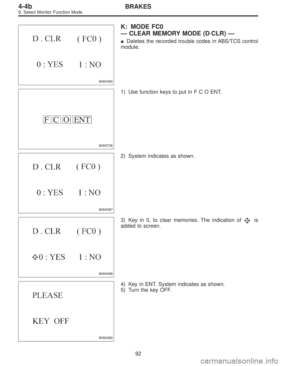
B4M0485
K: MODE FC0
—CLEAR MEMORY MODE (D⋅CLR)—
�Deletes the recorded trouble codes in ABS/TCS control
module.
B4M0736
1) Use function keys to put inFCOENT.
B4M0487
2) System indicates as shown.
B4M0488
3) Key in 0, to clear memories. The indication ofis
added to screen.
B4M0489
4) Key in ENT. System indicates as shown.
5) Turn the key OFF.
92
4-4bBRAKES
9. Select Monitor Function Mode
Page 2572 of 3342
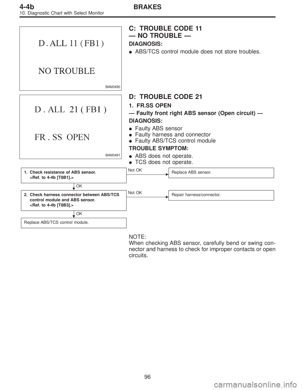
B4M0490
C: TROUBLE CODE 11
—NO TROUBLE—
DIAGNOSIS:
�ABS/TCS control module does not store troubles.
B4M0491
D: TROUBLE CODE 21
1. FR.SS OPEN
—Faulty front right ABS sensor (Open circuit)—
DIAGNOSIS:
�Faulty ABS sensor
�Faulty harness and connector
�Faulty ABS/TCS control module
TROUBLE SYMPTOM:
�ABS does not operate.
�TCS does not operate.
1. Check resistance of ABS sensor.
OK
�Not OK
Replace ABS sensor.
2. Check harness connector between ABS/TCS
control module and ABS sensor.
OK
�Not OK
Repair harness/connector.
Replace ABS/TCS control module.
NOTE:
When checking ABS sensor, carefully bend or swing con-
nector and harness to check for improper contacts or open
circuits.
�
�
96
4-4bBRAKES
10. Diagnostic Chart with Select Monitor
Page 2573 of 3342
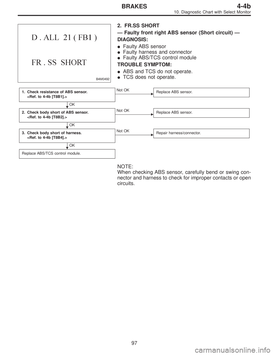
B4M0492
2. FR.SS SHORT
—Faulty front right ABS sensor (Short circuit)—
DIAGNOSIS:
�Faulty ABS sensor
�Faulty harness and connector
�Faulty ABS/TCS control module
TROUBLE SYMPTOM:
�ABS and TCS do not operate.
�TCS does not operate.
1. Check resistance of ABS sensor.
OK
�Not OK
Replace ABS sensor.
2. Check body short of ABS sensor.
OK
�Not OK
Replace ABS sensor.
3. Check body short of harness.
OK
�Not OK
Repair harness/connector.
Replace ABS/TCS control module.
NOTE:
When checking ABS sensor, carefully bend or swing con-
nector and harness to check for improper contacts or open
circuits.
�
�
�
97
4-4bBRAKES
10. Diagnostic Chart with Select Monitor
Page 2574 of 3342
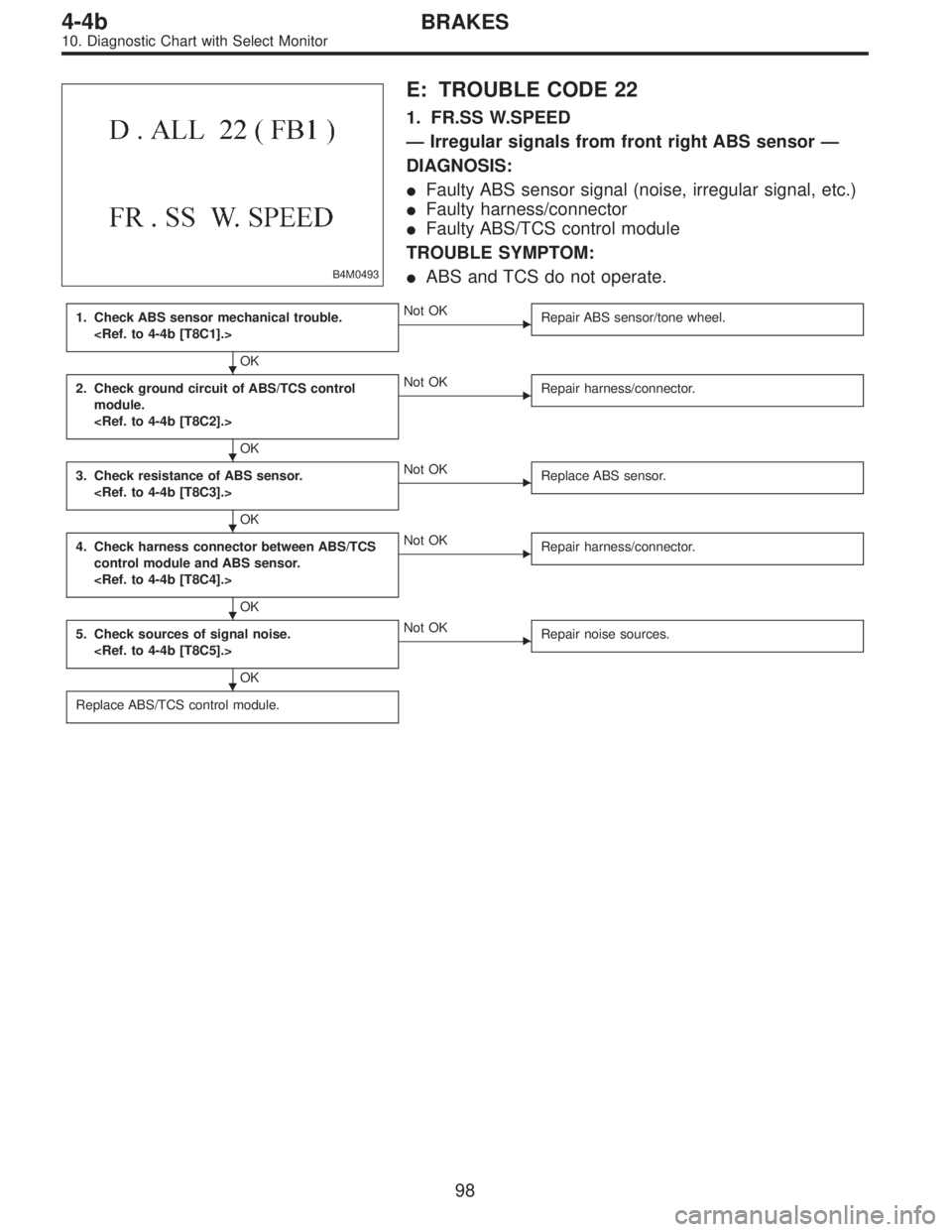
B4M0493
E: TROUBLE CODE 22
1. FR.SS W.SPEED
—Irregular signals from front right ABS sensor—
DIAGNOSIS:
�Faulty ABS sensor signal (noise, irregular signal, etc.)
�Faulty harness/connector
�Faulty ABS/TCS control module
TROUBLE SYMPTOM:
�ABS and TCS do not operate.
1. Check ABS sensor mechanical trouble.
OK
�Not OK
Repair ABS sensor/tone wheel.
2. Check ground circuit of ABS/TCS control
module.
OK
�Not OK
Repair harness/connector.
3. Check resistance of ABS sensor.
OK
�Not OK
Replace ABS sensor.
4. Check harness connector between ABS/TCS
control module and ABS sensor.
OK
�Not OK
Repair harness/connector.
5. Check sources of signal noise.
OK
�Not OK
Repair noise sources.
Replace ABS/TCS control module.
�
�
�
�
�
98
4-4bBRAKES
10. Diagnostic Chart with Select Monitor
Page 2575 of 3342
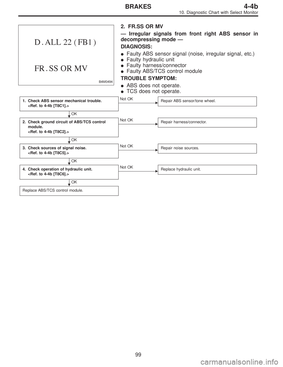
B4M0494
2. FR.SS OR MV
—Irregular signals from front right ABS sensor in
decompressing mode—
DIAGNOSIS:
�Faulty ABS sensor signal (noise, irregular signal, etc.)
�Faulty hydraulic unit
�Faulty harness/connector
�Faulty ABS/TCS control module
TROUBLE SYMPTOM:
�ABS does not operate.
�TCS does not operate.
1. Check ABS sensor mechanical trouble.
OK
�Not OK
Repair ABS sensor/tone wheel.
2. Check ground circuit of ABS/TCS control
module.
OK
�Not OK
Repair harness/connector.
3. Check sources of signal noise.
OK
�Not OK
Repair noise sources.
4. Check operation of hydraulic unit.
OK
�Not OK
Replace hydraulic unit.
Replace ABS/TCS control module.
�
�
�
�
99
4-4bBRAKES
10. Diagnostic Chart with Select Monitor
Page 2576 of 3342
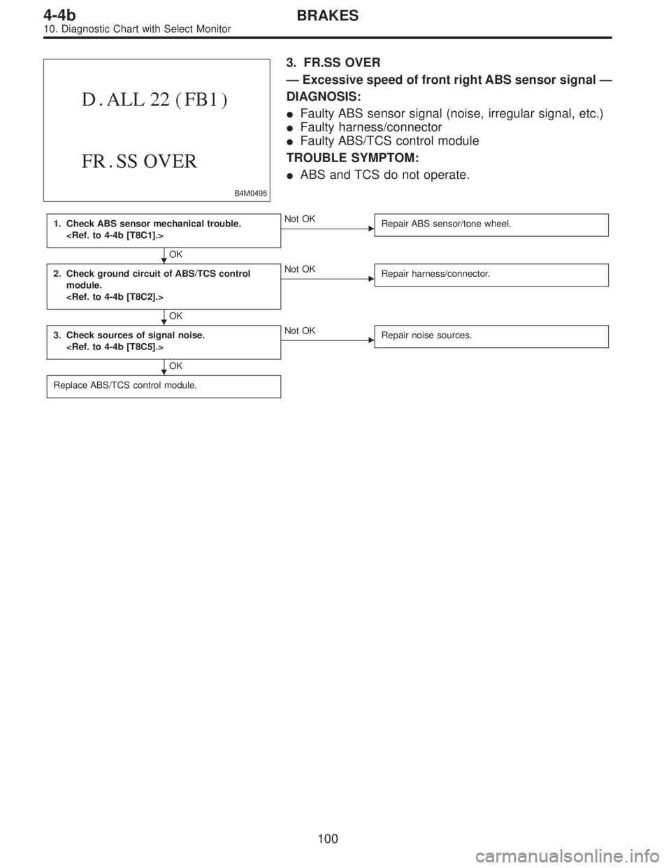
B4M0495
3. FR.SS OVER
—Excessive speed of front right ABS sensor signal—
DIAGNOSIS:
�Faulty ABS sensor signal (noise, irregular signal, etc.)
�Faulty harness/connector
�Faulty ABS/TCS control module
TROUBLE SYMPTOM:
�ABS and TCS do not operate.
1. Check ABS sensor mechanical trouble.
OK
�Not OK
Repair ABS sensor/tone wheel.
2. Check ground circuit of ABS/TCS control
module.
OK
�Not OK
Repair harness/connector.
3. Check sources of signal noise.
OK
�Not OK
Repair noise sources.
Replace ABS/TCS control module.
�
�
�
100
4-4bBRAKES
10. Diagnostic Chart with Select Monitor