Page 2521 of 3342
5. CHECK SOURCES OF SIGNAL NOISE.
1) Check that the mobile phone, personal radio and other
wireless apparatus are correctly installed.
2) Check that the antenna and other possible noise
sources are distant enough from the sensor harness.
3) Check that the sealed wires of the front harness sensor
(in the engine room) are securely grounded.
4) Check that between ABS/TCS control module and the
rear sensor harness has the correct twist pitch.
Twist pitch:
25 mm (0.98 in) or less
6. CHECK HYDRAULIC UNIT OPERATIONS.
1) Operate the ABS sequence control and check that the
brake fluid pressure at the malfunctioning brake line
increases and decreases properly.
45
4-4bBRAKES
8. Diagnostics Chart with Trouble Code
Page 2522 of 3342
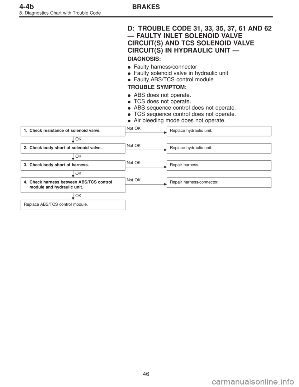
D: TROUBLE CODE 31, 33, 35, 37, 61 AND 62
—FAULTY INLET SOLENOID VALVE
CIRCUIT(S) AND TCS SOLENOID VALVE
CIRCUIT(S) IN HYDRAULIC UNIT—
DIAGNOSIS:
�Faulty harness/connector
�Faulty solenoid valve in hydraulic unit
�Faulty ABS/TCS control module
TROUBLE SYMPTOM:
�ABS does not operate.
�TCS does not operate.
�ABS sequence control does not operate.
�TCS sequence control does not operate.
�Air bleeding mode does not operate.
1. Check resistance of solenoid valve.
OK
�Not OK
Replace hydraulic unit.
2. Check body short of solenoid valve.
OK
�Not OK
Replace hydraulic unit.
3. Check body short of harness.
OK
�Not OK
Repair harness.
4. Check harness between ABS/TCS control
module and hydraulic unit.
OK
�Not OK
Repair harness/connector.
Replace ABS/TCS control module.
�
�
�
�
46
4-4bBRAKES
8. Diagnostics Chart with Trouble Code
Page 2524 of 3342
 Turn ignition switch OFF.
2) Disconnect connector from hydraulic unit.
3) Measure resistance between hydraulic unit terminals.
TROUBLE CODE / Connect")
B4M0723A
2. CHECK BODY SHORT OF SOLENOID VALVE.
1) Turn ignition switch OFF.
2) Disconnect connector from hydraulic unit.
3) Measure resistance between hydraulic unit terminals.
TROUBLE CODE / Connector & terminal:
31 / (F15) No. 3—body
33 / (F15) No. 4—body
35 / (F15) No. 1—body
37 / (F15) No. 2—body
61 / (F15) No. 12—body
62 / (F15) No. 11—body
Specified resistance: 1 MΩor more
B4M0419A
3. CHECK BODY SHORT OF HARNESS.
1) Turn ignition switch OFF.
2) Disconnect connector from hydraulic unit.
3) Disconnect connector from ABS/TCS control module.
4) Measure resistance between ABS/TCS control module
connector terminals.
TROUBLE CODE / Connector & terminal:
31 / (P5) No. 2—body
33 / (P4) No. 2—body
35 / (P4) No. 4—body
37 / (P5) No. 7—body
61 / (P4) No. 5—body
62 / (P5) No. 6—body
Specified resistance: 1 MΩor more
B4M0420A
4. CHECK HARNESS BETWEEN ABS/TCS CONTROL
MODULE AND HYDRAULIC UNIT.
1) Turn ignition switch OFF.
2) Connect connector to hydraulic unit.
3) Disconnect connector from ABS/TCS control module.
4) Measure resistance between ABS/TCS control module
connector terminals.
TROUBLE CODE / Connector & terminal:
31 / (P5) No. 2—(P6) No. 6
33 / (P4) No. 2—(P6) No. 6
48
4-4bBRAKES
8. Diagnostics Chart with Trouble Code
Page 2526 of 3342
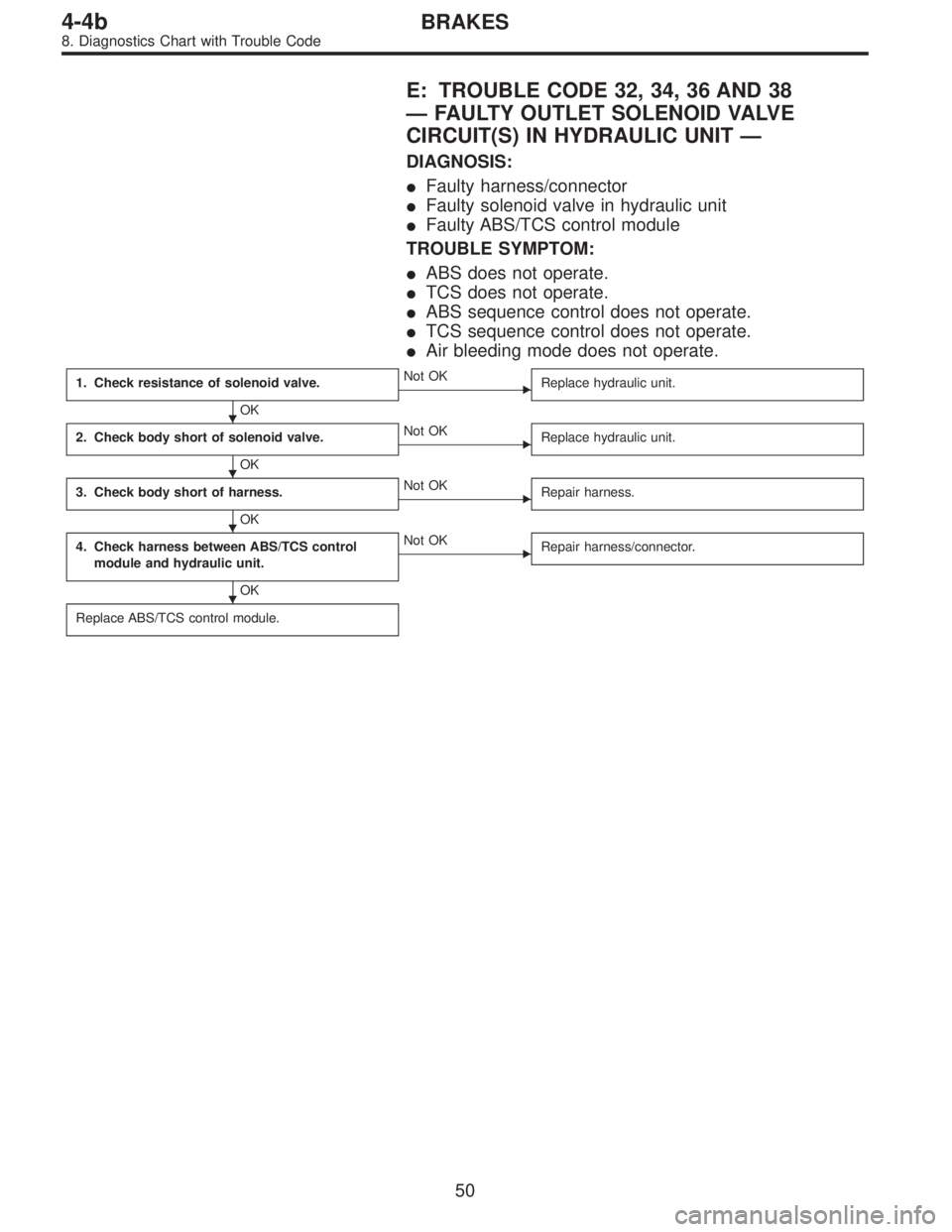
E: TROUBLE CODE 32, 34, 36 AND 38
—FAULTY OUTLET SOLENOID VALVE
CIRCUIT(S) IN HYDRAULIC UNIT—
DIAGNOSIS:
�Faulty harness/connector
�Faulty solenoid valve in hydraulic unit
�Faulty ABS/TCS control module
TROUBLE SYMPTOM:
�ABS does not operate.
�TCS does not operate.
�ABS sequence control does not operate.
�TCS sequence control does not operate.
�Air bleeding mode does not operate.
1. Check resistance of solenoid valve.
OK
�Not OK
Replace hydraulic unit.
2. Check body short of solenoid valve.
OK
�Not OK
Replace hydraulic unit.
3. Check body short of harness.
OK
�Not OK
Repair harness.
4. Check harness between ABS/TCS control
module and hydraulic unit.
OK
�Not OK
Repair harness/connector.
Replace ABS/TCS control module.
�
�
�
�
50
4-4bBRAKES
8. Diagnostics Chart with Trouble Code
Page 2528 of 3342
B4M0424A
3. CHECK BODY SHORT OF HARNESS.
1) Turn ignition switch OFF.
2) Disconnect connector from hydraulic unit.
3) Disconnect connector from ABS/TCS control module.
4) Measure resistance between ABS/TCS control module
connector terminals.
TROUBLE CODE / Connector & terminal:
32 / (P5) No. 3—body
34 / (P4) No. 1—body
36 / (P4) No. 3—body
38 / (P5) No. 8—body
Specified resistance: 1 MΩor more
B4M0425A
4. CHECK HARNESS BETWEEN ABS/TCS CONTROL
MODULE AND HYDRAULIC UNIT.
1) Turn ignition switch OFF.
2) Connect connector to hydraulic unit.
3) Disconnect connector from ABS/TCS control module.
4) Measure resistance between ABS/TCS control module
connector terminals.
TROUBLE CODE / Connector & terminal:
32 / (P5) No. 3—(P6) No. 6
34 / (P4) No. 1—(P6) No. 6
36 / (P4) No. 3—(P6) No. 6
38 / (P5) No. 8—(P6) No. 6
Specified resistance: 3.7±1.0Ω
52
4-4bBRAKES
8. Diagnostics Chart with Trouble Code
Page 2529 of 3342
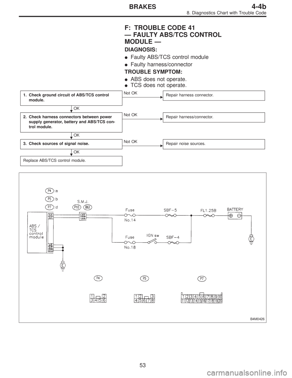
F: TROUBLE CODE 41
—FAULTY ABS/TCS CONTROL
MODULE—
DIAGNOSIS:
�Faulty ABS/TCS control module
�Faulty harness/connector
TROUBLE SYMPTOM:
�ABS does not operate.
�TCS does not operate.
1. Check ground circuit of ABS/TCS control
module.
OK
�Not OK
Repair harness connector.
2. Check harness connectors between power
supply generator, battery and ABS/TCS con-
trol module.
OK
�Not OK
Repair harness/connector.
3. Check sources of signal noise.
OK
�Not OK
Repair noise sources.
Replace ABS/TCS control module.
B4M0426
�
�
�
53
4-4bBRAKES
8. Diagnostics Chart with Trouble Code
Page 2530 of 3342
B4M0405A
1. CHECK GROUND CIRCUIT OF ABS/TCS CONTROL
MODULE.
1) Turn ignition switch OFF.
2) Disconnect connector from ABS/TCS control module.
3) Measure resistance between ABS/TCS control module
connector and body.
Connector & terminal / Specified resistance:
(P4) No. 6—body / 1Ωor less
(P5) No. 5—body / 1Ωor less
(P7) No. 15—body / 1Ωor less
2. CHECK HARNESS CONNECTORS BETWEEN
POWER SUPPLY GENERATOR, BATTERY AND ABS/
TCS CONTROL MODULE.
Check for poor contacts in plug-in connectors. Refer to
“Basic checks”in“FOREWORD”.
54
4-4bBRAKES
8. Diagnostics Chart with Trouble Code
Page 2531 of 3342
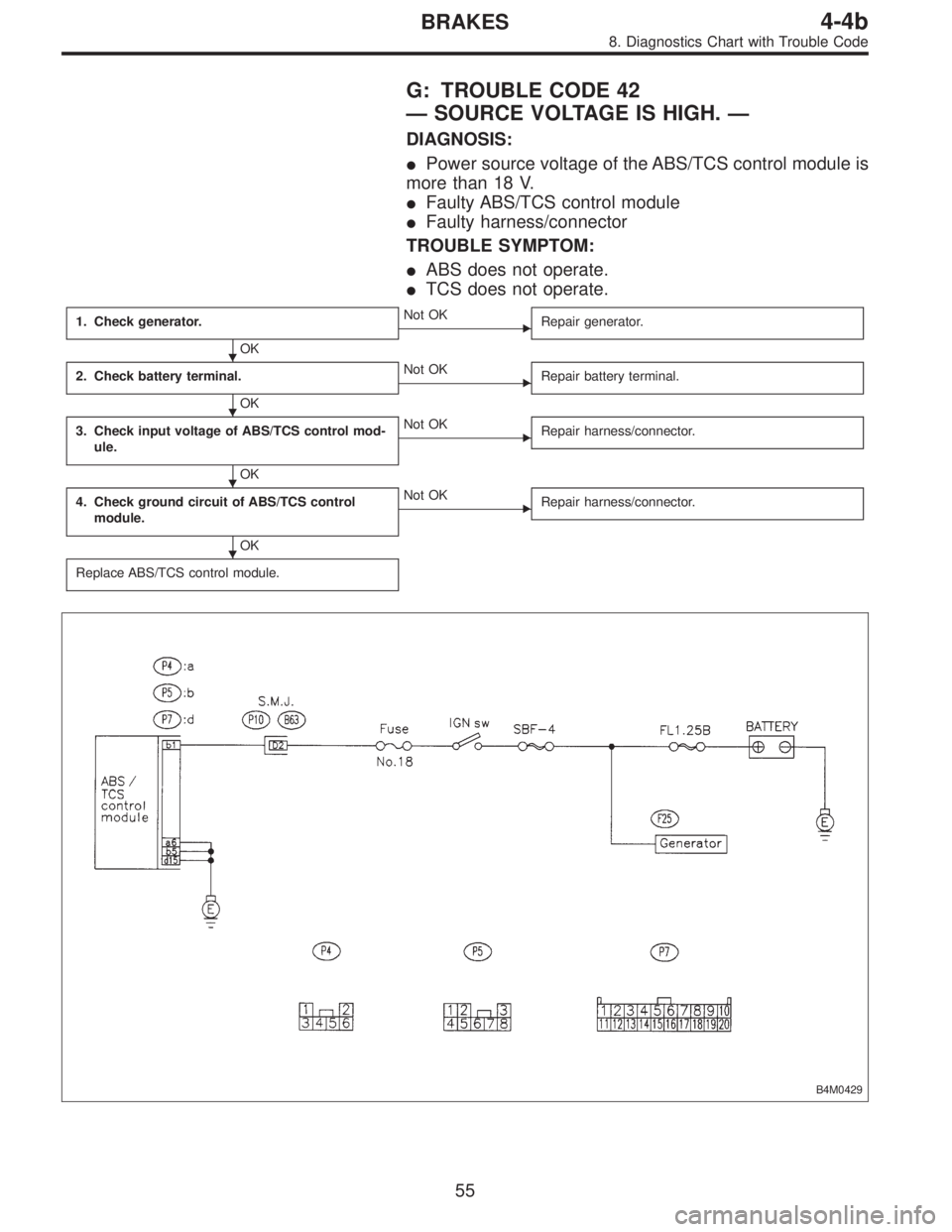
G: TROUBLE CODE 42
—SOURCE VOLTAGE IS HIGH.—
DIAGNOSIS:
�Power source voltage of the ABS/TCS control module is
more than 18 V.
�Faulty ABS/TCS control module
�Faulty harness/connector
TROUBLE SYMPTOM:
�ABS does not operate.
�TCS does not operate.
1. Check generator.
OK
�Not OK
Repair generator.
2. Check battery terminal.
OK
�Not OK
Repair battery terminal.
3. Check input voltage of ABS/TCS control mod-
ule.
OK
�Not OK
Repair harness/connector.
4. Check ground circuit of ABS/TCS control
module.
OK
�Not OK
Repair harness/connector.
Replace ABS/TCS control module.
B4M0429
�
�
�
�
55
4-4bBRAKES
8. Diagnostics Chart with Trouble Code
 Check that the mobile phone, personal radio and other
wireless apparatus are correctly installed.
2) Check that the antenna and other possible noise
sources are di")
 Turn ignition switch OFF.
2) Disconnect connector from hydraulic unit.
3) Disconnect connector from ABS/TCS control module.
4) Measure resistance between AB")
 Turn ignition switch OFF.
2) Disconnect connector from ABS/TCS control module.
3) Measure resistance between ABS/TCS control module
conne")