Page 896 of 3342
G3M0446
2) Remove the oil pump cover.
NOTE:
Lightly tap the end of the stator shaft to remove the cover.
G3M0447
3) Remove the retainer and return spring. Then remove
the rotor, two vane rings and nine vanes.
G3M0448
4) Remove the cam ring and control piston.
Also remove the O-ring, friction ring, two side seals, and
plain seal.
G3M0449
5) Remove two seal rings (R) and two seal rings (H).
B: INSPECTION
1) Make sure that each component is free of harmful
gouges, cuts, and dust.
90
3-2SERVICE PROCEDURE
7. Oil Pump Assembly
Page 897 of 3342
G3M0450
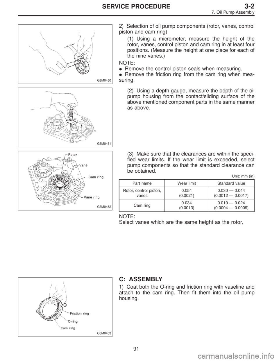
2) Selection of oil pump components (rotor, vanes, control
piston and cam ring)
(1) Using a micrometer, measure the height of the
rotor, vanes, control piston and cam ring in at least four
positions. (Measure the height at one place for each of
the nine vanes.)
NOTE:
�Remove the control piston seals when measuring.
�Remove the friction ring from the cam ring when mea-
suring.
G3M0451
(2) Using a depth gauge, measure the depth of the oil
pump housing from the contact/sliding surface of the
above mentioned component parts in the same manner
as above.
G3M0452
(3) Make sure that the clearances are within the speci-
fied wear limits. If the wear limit is exceeded, select
pump components so that the standard clearance can
be obtained.
Unit: mm (in)
Part name Wear limit Standard value
Rotor, control piston,
vanes0.054
(0.0021)0.030—0.044
(0.0012—0.0017)
Cam ring0.034
(0.0013)0.010—0.024
(0.0004—0.0009)
NOTE:
Select vanes which are the same height as the rotor.
G3M0453
C: ASSEMBLY
1) Coat both the O-ring and friction ring with vaseline and
attach to the cam ring. Then fit them into the oil pump
housing.
91
3-2SERVICE PROCEDURE
7. Oil Pump Assembly
Page 898 of 3342
G3M0454
2) Install the vane ring, rotor and vanes into the housing
in this sequence.
G3M0455
3) Install the return spring and retainer between the hous-
ing and cam ring.
G3M0456
4) Install the control piston to the oil pump housing.
NOTE:
Fit the seal in the piston groove, with the red seals facing
the top side. (Two side seals and one plain seal are
attached.)
5) Set the rotor at the center of the housing bore. Apply
ATF abundantly to each rotary portion.
G3M0446
6) Install the oil pump cover.
Tightening torque:
25±2 N⋅m (2.5±0.2 kg-m, 18.1±1.4 ft-lb)
NOTE:
�Align both pivots with the pivot holes of the cover, and
install the cover being careful not to apply undue force to
the pivots.
�After assembling, turn the oil pump shaft to check for
smooth rotation of the rotor.
G3M0449
NOTE:
�Install the oil seal retainer and seal rings (R) and (H)
after adjusting the drive pinion backlash and tooth contact.
92
3-2SERVICE PROCEDURE
7. Oil Pump Assembly
Page 997 of 3342
G3M0446
2) Remove the oil pump cover.
NOTE:
Lightly tap the end of the stator shaft to remove the cover.
G3M0447
3) Remove the retainer and return spring. Then remove
the rotor, two vane rings and nine vanes.
G3M0448
4) Remove the cam ring and control piston.
Also remove the O-ring, friction ring, two side seals, and
plain seal.
G3M0449
5) Remove two seal rings (R) and two seal rings (H).
B: INSPECTION
1) Make sure that each component is free of harmful
gouges, cuts, and dust.
90
3-2SERVICE PROCEDURE
7. Oil Pump Assembly
Page 998 of 3342

G3M0450
2) Selection of oil pump components (rotor, vanes, control
piston and cam ring)
(1) Using a micrometer, measure the height of the
rotor, vanes, control piston and cam ring in at least four
positions. (Measure the height at one place for each of
the nine vanes.)
NOTE:
�Remove the control piston seals when measuring.
�Remove the friction ring from the cam ring when mea-
suring.
G3M0451
(2) Using a depth gauge, measure the depth of the oil
pump housing from the contact/sliding surface of the
above mentioned component parts in the same manner
as above.
G3M0452
(3) Make sure that the clearances are within the speci-
fied wear limits. If the wear limit is exceeded, select
pump components so that the standard clearance can
be obtained.
Unit: mm (in)
Part name Wear limit Standard value
Rotor, control piston,
vanes0.054
(0.0021)0.030—0.044
(0.0012—0.0017)
Cam ring0.034
(0.0013)0.010—0.024
(0.0004—0.0009)
NOTE:
Select vanes which are the same height as the rotor.
G3M0453
C: ASSEMBLY
1) Coat both the O-ring and friction ring with vaseline and
attach to the cam ring. Then fit them into the oil pump
housing.
91
3-2SERVICE PROCEDURE
7. Oil Pump Assembly
Page 999 of 3342
G3M0454
2) Install the vane ring, rotor and vanes into the housing
in this sequence.
G3M0455
3) Install the return spring and retainer between the hous-
ing and cam ring.
G3M0456
4) Install the control piston to the oil pump housing.
NOTE:
Fit the seal in the piston groove, with the red seals facing
the top side. (Two side seals and one plain seal are
attached.)
5) Set the rotor at the center of the housing bore. Apply
ATF abundantly to each rotary portion.
G3M0446
6) Install the oil pump cover.
Tightening torque:
25±2 N⋅m (2.5±0.2 kg-m, 18.1±1.4 ft-lb)
NOTE:
�Align both pivots with the pivot holes of the cover, and
install the cover being careful not to apply undue force to
the pivots.
�After assembling, turn the oil pump shaft to check for
smooth rotation of the rotor.
G3M0449
NOTE:
�Install the oil seal retainer and seal rings (R) and (H)
after adjusting the drive pinion backlash and tooth contact.
92
3-2SERVICE PROCEDURE
7. Oil Pump Assembly
Page 1135 of 3342
G4M0217
9) Remove disc rotor from hub.
If disc rotor seizes up within hub, drive disc rotor out by
installing an 8-mm bolt in screw hole on the rotor.
G4M0218
10) Remove cotter pin and castle nut which secure tie-rod
end to housing knuckle arm.
G4M0219
11) Using a puller, remove tie-rod ball joint from knuckle
arm.
G4M0220
12) On A.B.S. equipped models, remove A.B.S. sensor
assembly and harness in advance.
CAUTION:
Be sure to use soft jaws (such as aluminum plates)
when placing the mating surfaces of housing and strut
in a vise.
G4M0221
13) Remove transverse link ball joint from housing.
10
4-2SERVICE PROCEDURE
1. Front Axle
Page 1140 of 3342
E: INSTALLATION
1) Install transverse link ball joint to housing.
Tightening torque:
44±6 N⋅m (4.5±0.6 kg-m, 32.5±4.3 ft-lb)
2) While aligning alignment mark on camber adjusting bolt
head, connect housing and strut.
CAUTION:
Use a new self-locking nut.
Tightening torque:
147±15 N⋅m (15±1.5 kg-m, 108±11 ft-lb)
3) Install speed sensor and harness on housing (only
vehicle equipped with A.B.S.).
4) Install disc rotor on hub.
5) Install disc brake caliper on housing.
Tightening torque:
59±10 N⋅m (6±1 kg-m, 43±7 ft-lb)
6) Install front drive shaft.
7) Connect stabilizer link.
G4M0236
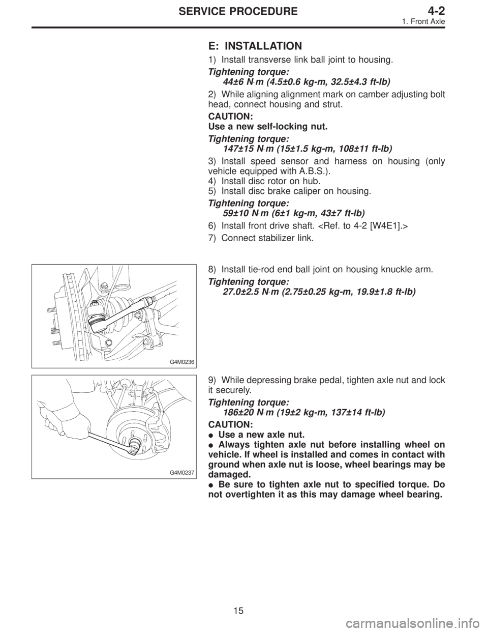
8) Install tie-rod end ball joint on housing knuckle arm.
Tightening torque:
27.0±2.5 N⋅m (2.75±0.25 kg-m, 19.9±1.8 ft-lb)
G4M0237
9) While depressing brake pedal, tighten axle nut and lock
it securely.
Tightening torque:
186±20 N⋅m (19±2 kg-m, 137±14 ft-lb)
CAUTION:
�Use a new axle nut.
�Always tighten axle nut before installing wheel on
vehicle. If wheel is installed and comes in contact with
ground when axle nut is loose, wheel bearings may be
damaged.
�Be sure to tighten axle nut to specified torque. Do
not overtighten it as this may damage wheel bearing.
15
4-2SERVICE PROCEDURE
1. Front Axle


