Page 2395 of 3342
OBD0527
CQ: DTC P1500
—RADIATOR FAN RELAY 1 CIRCUIT LOW
INPUT—
WIRING DIAGRAM:
B2M1296
NOTE:
Check radiator fan relay 1 circuit.
544
2-7ON-BOARD DIAGNOSTICS II SYSTEM
11. Diagnostic Chart with Trouble Code for RHD Vehicles
Page 2396 of 3342
OBD0538
CR: DTC P1502
—RADIATOR FAN FUNCTION PROBLEM—
WIRING DIAGRAM:
B2M1297
NOTE:
Check radiator fan control system.
545
2-7ON-BOARD DIAGNOSTICS II SYSTEM
11. Diagnostic Chart with Trouble Code for RHD Vehicles
Page 2400 of 3342
OBD0501
CV: DTC P1700
—THROTTLE POSITION SENSOR CIRCUIT
MALFUNCTION—
WIRING DIAGRAM:
B2M0613
NOTE:
Check throttle position sensor circuit for automatic trans-
mission.
549
2-7ON-BOARD DIAGNOSTICS II SYSTEM
11. Diagnostic Chart with Trouble Code for RHD Vehicles
Page 2401 of 3342
B2M0669
CW: DTC P1701
—CRUISE CONTROL SET SIGNAL CIRCUIT
MALFUNCTION—
WIRING DIAGRAM:
OBD0512
NOTE:
Check cruise control set signal circuit.
550
2-7ON-BOARD DIAGNOSTICS II SYSTEM
11. Diagnostic Chart with Trouble Code for RHD Vehicles
Page 2408 of 3342
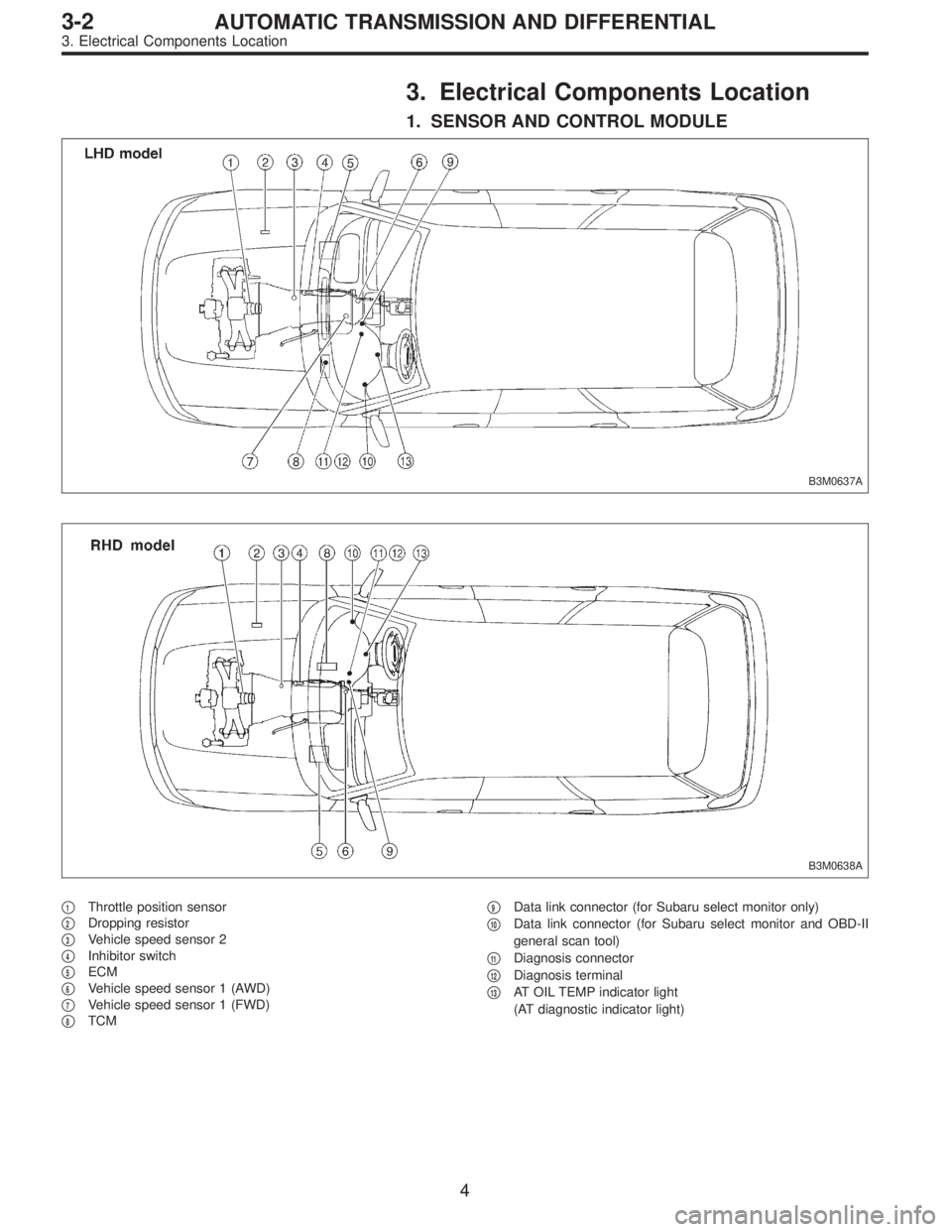
3. Electrical Components Location
1. SENSOR AND CONTROL MODULE
B3M0637A
B3M0638A
�1Throttle position sensor
�
2Dropping resistor
�
3Vehicle speed sensor 2
�
4Inhibitor switch
�
5ECM
�
6Vehicle speed sensor 1 (AWD)
�
7Vehicle speed sensor 1 (FWD)
�
8TCM�
9Data link connector (for Subaru select monitor only)
�
10Data link connector (for Subaru select monitor and OBD-II
general scan tool)
�
11Diagnosis connector
�
12Diagnosis terminal
�
13AT OIL TEMP indicator light
(AT diagnostic indicator light)
4
3-2AUTOMATIC TRANSMISSION AND DIFFERENTIAL
3. Electrical Components Location
Page 2409 of 3342
B2M0155AOBD0046A
B2M0211A
B3M0182C
B3M0183AB2M1043C
B3M0184AB3M0185A
5
3-2AUTOMATIC TRANSMISSION AND DIFFERENTIAL
3. Electrical Components Location
Page 2410 of 3342
B3M0443GB3M0445C
OBD0005COBD0006A
H3M1161AOBD0008D
6
3-2AUTOMATIC TRANSMISSION AND DIFFERENTIAL
3. Electrical Components Location
Page 2413 of 3342

I/O Signal
OBD0093A
Check with ignition switch ON.
ContentConnector
No.Terminal
No.Measuring conditions Voltage (V)
Back-up power supply B56 14 Ignition switch OFF")
5. Transmission Control Module (TCM)
I/O Signal
OBD0093A
Check with ignition switch ON.
ContentConnector
No.Terminal
No.Measuring conditions Voltage (V)
Back-up power supply B56 14 Ignition switch OFF 10—16
Ignition power supplyB54 6
Ignition switch ON (with engine OFF) 10—16
B55 1
Inhibitor switch“P”range switch B56 9Select lever in“P”range Less than 1
Select lever in any other than“P”
range (except“N”range)More than 8
“N”range switch B56 8Select lever in“N”range Less than 1
Select lever in any other than“N”
range (except“P”range)More than 8
“R”range switch B56 10Select lever in“R”range Less than 1
Select lever in any other than“R”
rangeMore than 6
“D”range switch B54 1Select lever in“D”range Less than 1
Select lever in any other than“D”
rangeMore than 6
“3”range switch B54 2Select lever in“3”range Less than 1
Select lever in any other than“3”
rangeMore than 6
“2”range switch B54 3Select lever in“2”range Less than 1
Select lever in any other than“2”
rangeMore than 6
“1”range switch B54 4Select lever in“1”range Less than 1
Select lever in any other than“1”
rangeMore than 6
Diagnosis switch B56 6Diagnosis connector connected Less than 1
Diagnosis connector disconnected More than 6
Brake switch B56 7Brake pedal depressed. More than 10.5
Brake pedal released. Less than 1
ABS signal B56 5ABS switch ON Less than 1
ABS switch OFF More than 6.5
AT diagnostic signal B55 12Ignition switch ON (With engine OFF) Less than 1
Ignition switch ON (With engine ON) More than 10
9
3-2AUTOMATIC TRANSMISSION AND DIFFERENTIAL
5. Transmission Control Module (TCM) I/O Signal
![SUBARU LEGACY 1997 Service Repair Manual OBD0527
CQ: DTC P1500
—RADIATOR FAN RELAY 1 CIRCUIT LOW
INPUT—
WIRING DIAGRAM:
B2M1296
NOTE:
Check radiator fan relay 1 circuit.
<Ref. to 2-7 [T10CT0].>
544
2-7ON-BOARD DIAGNOSTICS II SYSTEM
11. D](/manual-img/17/57434/w960_57434-2394.png "SUBARU LEGACY 1997 Service Repair Manual OBD0527
CQ: DTC P1500
—RADIATOR FAN RELAY 1 CIRCUIT LOW
INPUT—
WIRING DIAGRAM:
B2M1296
NOTE:
Check radiator fan relay 1 circuit.
<Ref. to 2-7 [T10CT0].>
544
2-7ON-BOARD DIAGNOSTICS II SYSTEM
11. D")
![SUBARU LEGACY 1997 Service Repair Manual OBD0538
CR: DTC P1502
—RADIATOR FAN FUNCTION PROBLEM—
WIRING DIAGRAM:
B2M1297
NOTE:
Check radiator fan control system.
<Ref. to 2-7 [T10CU0].>
545
2-7ON-BOARD DIAGNOSTICS II SYSTEM
11. Diagnostic](/manual-img/17/57434/w960_57434-2395.png "SUBARU LEGACY 1997 Service Repair Manual OBD0538
CR: DTC P1502
—RADIATOR FAN FUNCTION PROBLEM—
WIRING DIAGRAM:
B2M1297
NOTE:
Check radiator fan control system.
<Ref. to 2-7 [T10CU0].>
545
2-7ON-BOARD DIAGNOSTICS II SYSTEM
11. Diagnostic")
![SUBARU LEGACY 1997 Service Repair Manual OBD0501
CV: DTC P1700
—THROTTLE POSITION SENSOR CIRCUIT
MALFUNCTION—
WIRING DIAGRAM:
B2M0613
NOTE:
Check throttle position sensor circuit for automatic trans-
mission.
<Ref. to 2-7 [T10CY0].>
549](/manual-img/17/57434/w960_57434-2399.png "SUBARU LEGACY 1997 Service Repair Manual OBD0501
CV: DTC P1700
—THROTTLE POSITION SENSOR CIRCUIT
MALFUNCTION—
WIRING DIAGRAM:
B2M0613
NOTE:
Check throttle position sensor circuit for automatic trans-
mission.
<Ref. to 2-7 [T10CY0].>
549")
![SUBARU LEGACY 1997 Service Repair Manual B2M0669
CW: DTC P1701
—CRUISE CONTROL SET SIGNAL CIRCUIT
MALFUNCTION—
WIRING DIAGRAM:
OBD0512
NOTE:
Check cruise control set signal circuit.
<Ref. to 2-7 [T10CZ0].>
550
2-7ON-BOARD DIAGNOSTICS II](/manual-img/17/57434/w960_57434-2400.png "SUBARU LEGACY 1997 Service Repair Manual B2M0669
CW: DTC P1701
—CRUISE CONTROL SET SIGNAL CIRCUIT
MALFUNCTION—
WIRING DIAGRAM:
OBD0512
NOTE:
Check cruise control set signal circuit.
<Ref. to 2-7 [T10CZ0].>
550
2-7ON-BOARD DIAGNOSTICS II")