Page 644 of 3342
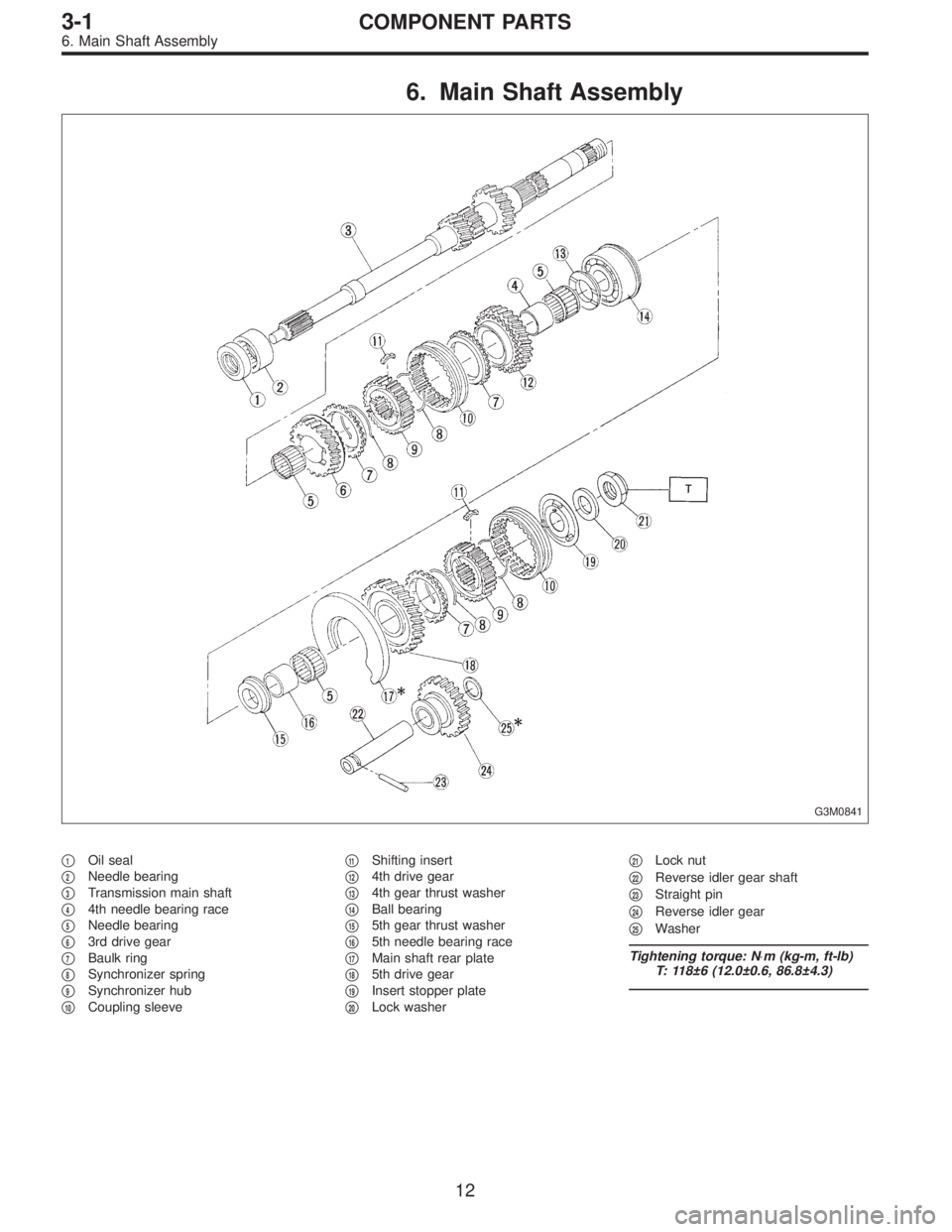
6. Main Shaft Assembly
G3M0841
�1Oil seal
�
2Needle bearing
�
3Transmission main shaft
�
44th needle bearing race
�
5Needle bearing
�
63rd drive gear
�
7Baulk ring
�
8Synchronizer spring
�
9Synchronizer hub
�
10Coupling sleeve�
11Shifting insert
�
124th drive gear
�
134th gear thrust washer
�
14Ball bearing
�
155th gear thrust washer
�
165th needle bearing race
�
17Main shaft rear plate
�
185th drive gear
�
19Insert stopper plate
�
20Lock washer�
21Lock nut
�
22Reverse idler gear shaft
�
23Straight pin
�
24Reverse idler gear
�
25Washer
Tightening torque: N⋅m (kg-m, ft-lb)
T: 118±6 (12.0±0.6, 86.8±4.3)
12
3-1COMPONENT PARTS
6. Main Shaft Assembly
Page 648 of 3342
 The following job should be followed before disassem-
bly:
(1) Clean oil, grease, dirt and dust from transmission.
(2) Remove drain plug�
1to drain oil. After draining,
reti")
B3M0037A
B: PRECAUTIONS
1) The following job should be followed before disassem-
bly:
(1) Clean oil, grease, dirt and dust from transmission.
(2) Remove drain plug�
1to drain oil. After draining,
retighten it as before.
CAUTION:
Replace gasket with a new one.
Tightening torque:
44±3 N⋅m (4.5±0.3 kg-m, 32.5±2.2 ft-lb)
G3M0517
(3) Attach transmission to ST.
ST 499937100 TRANSMISSION STAND SET
2) Rotating parts should be coated with oil prior to assem-
bly.
3) All disassembled parts, if to be reused, should be rein-
stalled in the original positions and directions.
4) Gaskets and lock washers must be replaced with new
ones.
5) Liquid gasket should be used where specified to pre-
vent leakage.
6) Fill transmission gear oil through the oil level gauge
hole up to upper point level gauge.
C: INSPECTION
Disassembled parts should be washed clean first and then
inspected carefully.
1) Bearings
Replace bearings in the following cases:
�Bearings whose balls, outer races and inner races are
broken or rusty.
�Worn bearings
�Bearings that fail to turn smoothly or make abnormal
noise when turned after gear oil lubrication.
B3M0038A
The ball bearing�3on the rear side of the drive pinion shaft
�
2should be checked for smooth rotation before the drive
pinion assembly is disassembled. In this case, because a
preload is working on the bearing, its rotation feels like it is
slightly dragging unlike the other bearings.
�Bearings having other defects
16
3-1SERVICE PROCEDURE
1. General
Page 663 of 3342
 Assembly of rear case is in the reverse order of disas-
sembly.
G3M0952
Tightening torque: N⋅m (kg-m, ft-lb)
T1: 6.4±0.5 (0.65±0.05, 4.7±0.4)
T2: 10±1 (1.0±0.1, 7.2±0.7)
T3: 25�")
B: ASSEMBLY
1) Assembly of rear case is in the reverse order of disas-
sembly.
G3M0952
Tightening torque: N⋅m (kg-m, ft-lb)
T1: 6.4±0.5 (0.65±0.05, 4.7±0.4)
T2: 10±1 (1.0±0.1, 7.2±0.7)
T3: 25±5 (2.5±0.5, 18.1±3.6)
2) Installation of shifter arm�6
Install shifter arm into the partition from the front while
inserting selector arm into the opening in reverse check
sleeve. Pass shaft through hole in selector arm until its end
comes out of the rear of transmission case assembly.
CAUTION:
Apply a coat of gear oil to shifter arm. Also make sure
oil seal is positioned properly.
3) Adjustment of neutral position
NOTE:
After assembling and installing rear case, adjust neutral
position.
(1) Shift gear into 3rd gear position.
(2) Shifter arm turns lightly toward the 1st/2nd gear
side but heavily toward the reverse gear side because
of the function of the return spring, until arm contacts
the stopper.
(3) Make adjustment so that the heavy stroke (reverse
side) is a little more than the light stroke (1st/2nd side).
(4) To adjust, remove bolts holding reverse check
sleeve assembly to the case, move sleeve assembly
outward, and place adjustment shim (0 to 1 ea.)
between sleeve assembly and case to adjust the clear-
ance.
31
3-1SERVICE PROCEDURE
3. Rear Case (FWD Model)
Page 666 of 3342
G3M0598
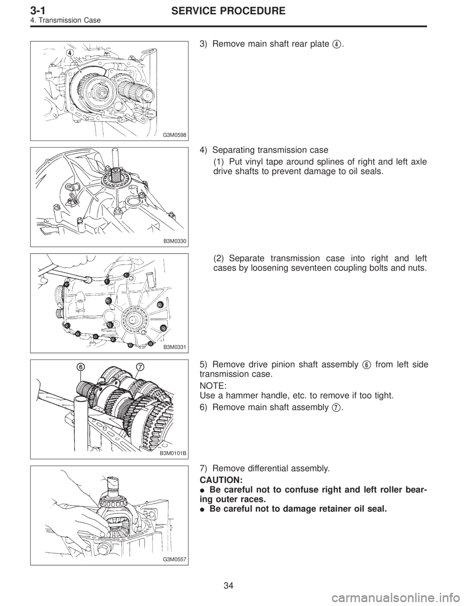
3) Remove main shaft rear plate�4.
B3M0330
4) Separating transmission case
(1) Put vinyl tape around splines of right and left axle
drive shafts to prevent damage to oil seals.
B3M0331
(2) Separate transmission case into right and left
cases by loosening seventeen coupling bolts and nuts.
B3M0101B
5) Remove drive pinion shaft assembly�6from left side
transmission case.
NOTE:
Use a hammer handle, etc. to remove if too tight.
6) Remove main shaft assembly�
7.
G3M0557
7) Remove differential assembly.
CAUTION:
�Be careful not to confuse right and left roller bear-
ing outer races.
�Be careful not to damage retainer oil seal.
34
3-1SERVICE PROCEDURE
4. Transmission Case
Page 668 of 3342
 Drive out spring pin�6, and pull out 3-4 fork rod�7and
shifter fork�
8.
NOTE:
When removing rod, keep other rods in neutral. Also, when
pulling out straight pin, remove it toward inside of")
B3M0333B
3) Drive out spring pin�6, and pull out 3-4 fork rod�7and
shifter fork�
8.
NOTE:
When removing rod, keep other rods in neutral. Also, when
pulling out straight pin, remove it toward inside of case so
that it may not hit against case.
4) Drive out straight pin�
9, and pull out 1-2 fork rod�10and
shifter fork�
11.
G3M0602
5) Pull out straight pin�12, and remove idler gear shaft�13,
reverse idler gear�
14and washer�15.
6) Remove outer snap ring�
16, and pull out reverse shifter
rod arm�
17from reverse fork rod�18. Then take out ball,
spring and interlock plunger from rod.
And then remove rod.
NOTE:
When pulling out reverse shifter rod arm, be careful not to
let ball pop out of arm.
7) Remove reverse shifter lever�
19.
G3M0546
8) Remove differential side retainers using ST.
ST 499787000 WRENCH ASSY
G3M0547
9) Remove outer snap ring�20and pull out speedometer
driven gear�
21. Next, remove vehicle speed sensor 2, oil
seal, speedometer shaft�
22and washer.
36
3-1SERVICE PROCEDURE
4. Transmission Case
Page 672 of 3342
G3M0552
9) Position balls�17, checking ball springs�18and gaskets
�
19into 3-4 and 1-2 rod holes, and install plugs�20.
CAUTION:
Replace gasket with a new one.
G3M0547
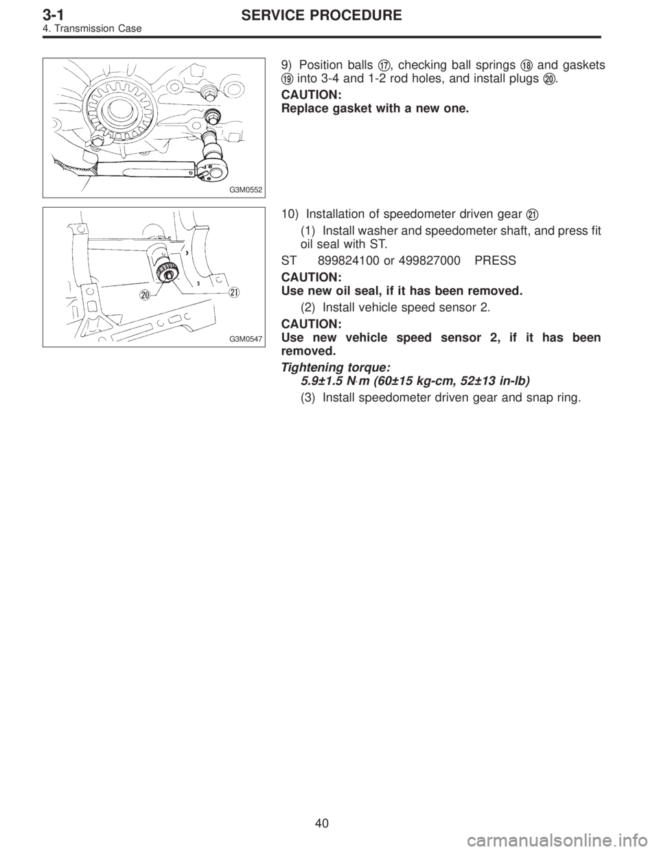
10) Installation of speedometer driven gear�21
(1) Install washer and speedometer shaft, and press fit
oil seal with ST.
ST 899824100 or 499827000 PRESS
CAUTION:
Use new oil seal, if it has been removed.
(2) Install vehicle speed sensor 2.
CAUTION:
Use new vehicle speed sensor 2, if it has been
removed.
Tightening torque:
5.9±1.5 N⋅m (60±15 kg-cm, 52±13 in-lb)
(3) Install speedometer driven gear and snap ring.
40
3-1SERVICE PROCEDURE
4. Transmission Case
Page 675 of 3342
 Install differential assembly�3on left hand transmission
case.
CAUTION:
Be careful not to fold the sealing lip of oil seal.
NOTE:
Wrap the left and right splined sections of axle shaft with")
G3M0557
3) Install differential assembly�3on left hand transmission
case.
CAUTION:
Be careful not to fold the sealing lip of oil seal.
NOTE:
Wrap the left and right splined sections of axle shaft with
vinyl tape to prevent scratches.
G3M0558
4) Install needle bearing and oil seal onto the front of
transmission main shaft assembly�
4, and position in left
side transmission case.
CAUTION:
�Wrap clutch splined section with vinyl tape to pre-
vent damage to oil seal.
�Apply grease (Unilube #2 or equivalent) to the seal-
ing lip of oil seal.
NOTE:
�Align the end face of seal with surface A of left side
transmission main case when installing oil seal.
�Be careful not to drop oil seal when installing right side
transmission main case.
�Make sure straight pin is positioned in hole in needle
bearing’s outer race.
G3M0575
5) Install drive pinion shaft assembly�5with shims
selected before into transmission case.
NOTE:
Ensure that the knock pin of the case is fitted into the hole
in the bearing outer race.
43
3-1SERVICE PROCEDURE
4. Transmission Case
Page 677 of 3342
 Combination of transmission case
(1) Wipe off grease, oil and dust on the mating sur-
faces of transmission cases with white gasoline, and
apply liquid gasket, and then put case ri")
B3M0399A
B3M0331
8) Combination of transmission case
(1) Wipe off grease, oil and dust on the mating sur-
faces of transmission cases with white gasoline, and
apply liquid gasket, and then put case right side and left
side together.
Liquid gasket:
THREE BOND 1215 or equivalent
(2) Tighten 17 bolts with bracket, clip, etc. as shown in
the figure.
Tightening torque:
8 mm bolt
25±2 N⋅m (2.5±0.2 kg-m, 18.1±1.4 ft-lb)
�10 mm bolt
39±3 N⋅m (4.0±0.3 kg-m, 28.9±2.2 ft-lb)
NOTE:
�Insert bolts from the bottom and tighten nuts at the top.
�Put cases together so that drive pinion shim and input
shaft holder shim are not caught up in between.
�Confirm that counter gear and speedometer gear are
meshed.
G3M0597
9) Tighten ball bearing attachment bolts.
Tightening torque:
29±3 N⋅m (3.0±0.3 kg-m, 21.7±2.2 ft-lb)
G3M0563
10) Backlash adjustment of hypoid gear and preload
adjustment of roller bearing
NOTE:
Support drive pinion assembly with ST.
ST 498427100 STOPPER
45
3-1SERVICE PROCEDURE
4. Transmission Case