Page 123 of 3342

Start
the
engine
.
2)
Idle
the
engine
.")
BRAKES
[ABS
5
.3i
TYPE]
[T1
0C4]
4-4d
10
.
Diagnostics
Chart
with
Select
Monitor
1~
\
v
ILIA
m(l
(l
n
!~
5r
J
%
B4M0430
1
10C1
I
CHECKGENERATOR
.I
1)
Start
the
engine
.
2)
Idle
the
engine
.
3)
Measure
voltage
between
generator
and
chassis
ground
.
Terminal
Generator
B
terminal
(+)
-
Chassis
ground
(
)
:
CHECK
;
Is
the
voltage
between
10
and
15
V?
Go
tostep
10C2
.
No
:
Repair
generator
.
10C2
CHECK
BATTERY
TERMINAL
.
Turn
ignition
switch
to
OFF
.
CHECK
:
Is
there
poor
contact
at
battery
terminal?
,rES
:
Repair
battery
terminal
.
No
:
Go
to
step
10C3
.
10C3
CHECK
I
MONITOR
.
MMUNICATION
OF
SELECT
Using
the
select
monitor,
check
whether
communication
to
other
system(suchas
engine,
AT,
etc
.)
can
be
executed
normally
.
CHECK
:
Are
the
name
and
year
ofthe
system
dis-
played
on
theselect
monitor?
Go
to
step
10C4
.
No
:
Repair
select
monitor
communication
cable
and
connector
.
10C4
CHECK
I
CONNECTOR
.
INSTALLATION
OF
ABSCM&H/U
Turn
ignition
switch
to
OFF
.
CHECK
:
Is
ABSCM&HIU
connector
inserted
into
ABSCM&HlU
until
the
clamp
locks
onto
it?
Go
to
step
10C5
.
n~o
:
Insert
ABSCM&H/U
connector
into
ABSCM&H/U
until
the
clamp
locks
onto
it
.
105
Page 131 of 3342
![SUBARU LEGACY 1997 Service Repair Manual
4-4d
[T1oHyl
BRAKES
[ABS
5
.3i
TYPE]
10
.
Diagnostics
Chart
with
Select
Monitor
FR
(F05)
30
km/h
B4M0922
I1
0H1
(CHECK
OUTPUT
SELECT
MONITORF
ABS
SENSOR
USING
Read
the
ABS
sensoroutput
corres](/manual-img/17/57434/w960_57434-130.png "SUBARU LEGACY 1997 Service Repair Manual
4-4d
[T1oHyl
BRAKES
[ABS
5
.3i
TYPE]
10
.
Diagnostics
Chart
with
Select
Monitor
FR
(F05)
30
km/h
B4M0922
I1
0H1
(CHECK
OUTPUT
SELECT
MONITORF
ABS
SENSOR
USING
Read
the
ABS
sensoroutput
corres")
4-4d
[T1oHyl
BRAKES
[ABS
5
.3i
TYPE]
10
.
Diagnostics
Chart
with
Select
Monitor
FR
(F05)
30
km/h
B4M0922
I1
0H1
(CHECK
OUTPUT
SELECT
MONITORF
ABS
SENSOR
USING
Read
the
ABS
sensoroutput
corresponding
to
the
faulty
system
in
the
select
monitor
function
mode
.
NOTE
:
The
select
monitor
display
shows
that
the
front
right
wheel
is
rotating
at
30km/h
.
CHECK
:
Does
the
speed
indicated
on
the
display
change
in
response
to
the
speedometer
reading
during
acceleration/deceleration
when
the
steering
wheel
isin
the
straight-
ahead
position?
YES
:
Go
to
step
10H2
.
No
:
Go
to
step
10H9
.
1OH2
I
HECK
INSTALLATION
OF
ABS
SENSOR
.
Tighteningtorque
:
32
f
10
N~
m
(3.3
f
1
.0
kg-m,
24
±
7
ft-Ib)
CHECK
:
Are
the
ABS
sensor
installation
bolts
tight-
ened
securely?
,rES
:
Go
to
step
10H3
.
No
:
Tighten
ABS
sensor
installation
bolts
securely
.
10H3
I
CHECK
INSTALLATION
OFTONE
WHEEL
.
Tightening
torque
:
13±3
N~m
(1
.3±0
.3
kg-m,
9±2
.2
ft-Ib)
CHECK
:
Are
the
tone
wheel
installation
bolts
tight-
ened
securely?
ves
:
Go
to
step
10H4
.
No
:
Tightentone
wheel
installation
bolts
securely
.
114
Page 135 of 3342
![SUBARU LEGACY 1997 Service Repair Manual
4-4d
[r1oHy3l
BRAKES
[ABS
5
.31
TYPE]
10
.
Diagnostics
Chart
withSelect
Monitor
F49
B4M1240A
I
I
-
r10H13
CHECK
BATTERY
SHORT
OFHARNESS
.
Measure
voltage
between
ABSCM&H/U
connector
and
chassis](/manual-img/17/57434/w960_57434-134.png "SUBARU LEGACY 1997 Service Repair Manual
4-4d
[r1oHy3l
BRAKES
[ABS
5
.31
TYPE]
10
.
Diagnostics
Chart
withSelect
Monitor
F49
B4M1240A
I
I
-
r10H13
CHECK
BATTERY
SHORT
OFHARNESS
.
Measure
voltage
between
ABSCM&H/U
connector
and
chassis")
4-4d
[r1oHy3l
BRAKES
[ABS
5
.31
TYPE]
10
.
Diagnostics
Chart
withSelect
Monitor
F49
B4M1240A
I
I
-
r10H13
CHECK
BATTERY
SHORT
OFHARNESS
.
Measure
voltage
between
ABSCM&H/U
connector
and
chassis
ground
.
Connector
&
terminal
Trouble
code
21
I
(F49)
No
.
11
(+)
-
Chassis
ground
Trouble
code
23
/
(F49)
No
.
9
(+)
-
Chassis
ground
Trouble
code
25
/
(F49)
No
.
14
(+)
-
Chassis
ground
l-)~
Trouble
code
27
/
(F49)
No
.
7
(+)
-
Chassis
ground
CHECK
:
Is
thevoltage
less
than
1
V?
,rES
:
Go
to
step
10H14
.
No
:
Repair
harness
between
ABSCM&H/U
and
ABS
sensor
.
I10H14
CHECK
BATTERY
SHORT
OFHARNESS
.
1)
Turn
ignition
switch
to
ON
.
2)
Measure
voltage
between
ABSCM&H/U
connector
and
chassis
ground
.
Connector
&
terminal
Trouble
code
21
/
(F49)
No
.
11
(+)
-
Chassis
ground
Trouble
code
23
/
(F49)
No
.
9
(+)
-
Chassis
ground
(-)
Trouble
code
25
I
(F49)
No
.
14
(+)
-
Chassis
ground
Trouble
code
27
/
(F49)
No
.
7
(+)
-
Chassis
ground
(-)
CHECK
:
Is
thevoltage
less
than
1
V?
,rES
:
Go
to
step
10H15
.
No
:
Repair
harness
between
ABSCM&H/U
and
ABS
sensor
.
1
10H15
I
CHECK
INSTALLATION
OF
ABS
SENSOR
.
Tightening
torque
:
32
±
10
N~m
(3
.3
f
1
.0
kg-m,
24
f
7
ft-Ib)
CHECK
:
Are
the
ABS
sensor
installation
bolts
tight-
ened
securely?
,res
:
Go
to
step
10H16
.
No
:
Tighten
ABS
sensor
installation
bolts
securely
.
118
Page 136 of 3342
BRAKES
LABS
5
.31
TYPE]
[T10H18]
4-4d
10
.
Diagnostics
Chart
with
Select
Monitor
G4M0700I
G4M0701
I
10H16
I
CHECK
INSTALLATION
OF
TONE
WHEEL
.
Tightening
torque
:
13
f
3
N~m
(1
.3
f
0
.3
kg-m,
9
f
2
.2
ft-Ib)
CHECK
:
Are
thetone
wheel
installation
bolts
tight-
ened
securely?
vES
:
Go
to
step
10H17
.
No
:
Tightentone
wheel
installation
bolts
securely
.
(CHECK
ABS
SENSOR
GAP
.
Measure
tone
wheel-to-poke
piece
gap
over
entire
perim-
eterof
the
wheel
.
CHECK
:
Is
the
gap
within
the
specifications
shown
in
the
following
table?
Front
wheel
Rear
wheel
Specifications
0
.9
-
1
.4
mm
(0
.035
-
0
.055
in)
0
.7
-
1
.2
mm
(0
.028
-
0
.047
in)
,rES
:
Go
tostep
10H18
.
No
:
Adjust
the
gap
.
NOTE
:
Adjustthe
gap
using
spacers
(Part
No
.
26755AA000)
.
If
spacers
cannot
correct
the
gap,
replace
worn
sensor
or
worn
tone
wheel
.
10H18
CHECK
HUB
RUNOUT
.
Measure
hub
runout
.
CHECK
:
Is
the
runout
less
than0
.05
mm
(0
.0020
in)?
Go
tostep
10H19
.
No
:
Repair
hub
.
119
T
Sensorgap
Sensor
gap
Page 142 of 3342
BRAKES
[ABS
5
.31
TYPE]
[r1oLs1
4-4d
10
.
Diagnostics
Chart
with
Select
Monitor
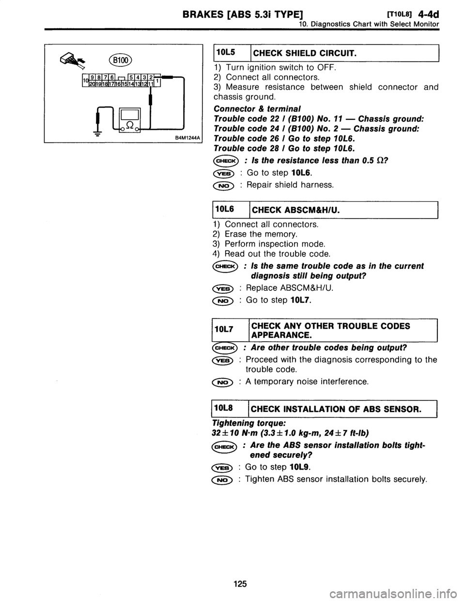
8100
1
91817161
5
1
4
1
3
21
2
191
76
51
11
11
J
84M1244A
10L5
CHECK
SHIELD
CIRCUIT
.
1)
Turn
ignition
switch
to
OFF
.
2)
Connect
all
connectors
.
3)
Measure
resistance
between
shield
connector
and
chassis
ground
.
Connector
&
terminal
Trouble
code
22
I
(8100)
No
.
11
-
Chassis
ground
:
Trouble
code
24
!
(8100)
No
.
2
-
Chassis
ground
:
Trouble
code
26
l
Go
to
step
10L6
.
Trouble
code
28
I
Go
to
step
10L6
.
CHECK
:
Is
the
resistance
less
than0
.5
S2?
Go
to
step
10L6
.
No
:
Repair
shield
harness
.
10L6
CHECK
ABSCM&H/U
.
1)
Connect
all
connectors
.
2)
Erase
the
memory
.
3)
Perform
inspection
mode
.
4)
Read
out
the
trouble
code
.
CHECK
:
Is
the
same
trouble
code
as
in
the
current
diagnosis
still
being
output?
Replace
ABSCM&H/U
.
No
:
Go
to
step
10L7
.
10L7
CHECK
ANY
OTHER
TROUBLE
CODES
APPEARANCE
.
CHECK
:
Are
othertrouble
codes
being
output?
Proceed
withthe
diagnosis
corresponding
to
the
trouble
code
.
No
:
A
temporary
noise
interference
.
11011-8
1
CHECK
INSTALLATION
OF
ABS
SENSOR
.
I
Tightening
torque
:
32
f
10
N~m
(3
.3
f
1
.0
kg-m,
24
f
7
ft-Ib)
Are
the
ABS
sensor
installation
bolts
tight-
ened
securely?
Go
to
step
10L9
.
Tighten
ABS
sensor
installation
bolts
securely
.
125
Page 143 of 3342
4-4d
[TIoL9]
BRAKES
[ABS
5
.31
TYPE]
10
.
Diagnostics
Chart
with
Select
Monitor
G4M0700I
G4M0701
I
10L9
I
CHECK
INSTALLATION
OFTONE
WHEEL
.
Tightening
torque
:
13
f
3
N~m
(1
.3
f
0
.3
kg-m,
9
f
2
.2
ft-Ib)
CHECK
:
Are
thetone
wheel
installation
bolts
tight-
ened
securely?
vES
:
Go
to
step
10L10
.
No
:
Tighten
tone
wheel
installation
bolts
securely
.
1
10L10
I
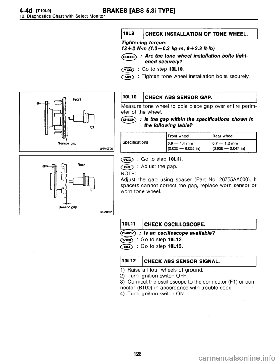
CHECK
ABS
SENSOR
GAP
.
Measure
tone
wheel
to
pole
piece
gap
over
entire
perim-
eter
of
the
wheel
.
CHECK
;
Is
the
gap
within
the
specifications
shown
in
the
following
table?
Front
wheel
Rear
wheel
Specifications
0
.9
-
1
.4
mm
(0
.035
-
0
.055
in)
0
.7
-
1
.2
mm
(0
.028
-
0
.047
in)
vES
:
Go
to
step
10L11
.
No
:
Adjust
the
gap
.
NOTE
:
Adjustthe
gap
using
spacer
(Part
No
.
26755AA000)
.
If
spacers
cannot
correct
the
gap,
replace
worn
sensor
or
worn
tone
wheel
.
1
10L11
I
CHECK
OSCILLOSCOPE
.
I
CHECK
;
Is
an
oscilloscopeavailable?
,rES
:
Go
to
step
10L12
.
No
:
Go
to
step
10L13
.
1
10L12
I
CHECK
ABS
SENSOR
SIGNAL
.
1)
Raise
all
four
wheels
of
ground
.
2)
Turn
ignition
switch
OFF
.
3)
Connect
the
oscilloscope
to
the
connector
(F1)
or
con-
nector
(B100)
in
accordance
with
trouble
code
.
4)
Turn
ignition
switch
ON
.
126
t
Sensorgap
Sensorgap
Page 150 of 3342
BRAKES
[ABS
5
.31
TYPE]
[T10M5]
4-4d
10
.
Diagnostics
Chart
with
Select
Monitor
iomi
CHECK
(FREE
Y'FOR
THE
AILONG
TIMEVE
TURNED
CHECK
:
Check
if
the
wheels
have
been
turned
freely
for
more
than
one
minute,
suchas
when
the
vehicle
is
jacked-up,
under
full-lock
corner-
ing
or
when
fire
is
not
in
contact
with
road
surface
.
,rES
:
The
ABS
is
normal
.
Erase
the
trouble
code
.
NOTE
:
When
the
wheels
turn
freelyfor
a
long
time,
such
as
when
the
vehicle
is
towed
or
jacked-up,
or
when
steering
wheel
is
continuously
turned
all
the
way,
this
trouble
code
may
sometimes
occur
.
No
:
Go
to
step
10M2
.
10M2
CHECK
TIRE
SPECIFICATIONS
.
Turn
ignition
switch
to
OFF
.
CHECK
:
Are
the
fire
specifications
correct?
,rES
:
Go
to
step
10M3
.
No
:
Replace
tire
.
1
10M3
I
CHECK
WEAR
OF
TIRE
.
Is
the
fire
worn
excessively?
vES
:
Replace
tire
.
No
:
Go
to
step
10M4
.
1
10M4
I
CHECK
TIRE
PRESSURE
.
CHECK
:
Is
the
fire
pressure
correct?
Go
to
step
10M5
.
No
:
Adjust
fire
pressure
.
1
10M5
I
CHECK
INSTALLATION
OF
ABS
SENSOR
.
Tightening
torque
:
32
f
10
N~m
(3
.3
f
1
.0
kg-m,
24
f
7
ft-Ib)
CHECK
:
Are
the
ABS
sensor
installation
bolts
tight-
ened
securely?
,rES
:
Go
to
step
10M6
.
No
:
Tighten
ABS
sensor
installation
bolts
securely
.
133
Page 151 of 3342
![SUBARU LEGACY 1997 Service Repair Manual
4-4d
[rionns1
BRAKES
[ABS
5
.31
TYPE]
10
.
Diagnostics
Chart
withSelect
Monitor
G4M0700
I
G4M0701
I
1
101111116
I
CHECK
INSTALLATION
OF
TONE
WHEEL
.
Tightening
torque
:
13
±
3
N~m
(1.3
f
0
.3
k](/manual-img/17/57434/w960_57434-150.png "SUBARU LEGACY 1997 Service Repair Manual
4-4d
[rionns1
BRAKES
[ABS
5
.31
TYPE]
10
.
Diagnostics
Chart
withSelect
Monitor
G4M0700
I
G4M0701
I
1
101111116
I
CHECK
INSTALLATION
OF
TONE
WHEEL
.
Tightening
torque
:
13
±
3
N~m
(1.3
f
0
.3
k")
4-4d
[rionns1
BRAKES
[ABS
5
.31
TYPE]
10
.
Diagnostics
Chart
withSelect
Monitor
G4M0700
I
G4M0701
I
1
101111116
I
CHECK
INSTALLATION
OF
TONE
WHEEL
.
Tightening
torque
:
13
±
3
N~m
(1.3
f
0
.3
kg-m,
9
±
2
.2
ft-Ib)
CHECK
:
Are
thetone
wheel
installation
bolts
tight-
ened
securely?
,rES
:
Go
to
step
10M7
.
No
:
Tightentone
wheel
installation
bolts
securely
.
CHECK
ABS
SENSOR
GAP
.
Measure
tone
wheel
to
pole
piece
gap
over
entire
perim-
eterof
the
wheel
.
CHECK
:
Is
the
gap
within
the
specifications
shown
in
the
following
fable?
Front
wheel
Rear
wheel
Specifications
0
.9
-
1
.4
mm
(0
.035
-
0
.055
in)
0
.7
-
1
.2
mm
(0
.028
-
0
.047
in)
Go
tostep
10M8
.
No
:
Adjustthe
gap
.
NOTE
:
Adjustthe
gap
using
spacer
(Part
No
.
26755AA000)
.
If
spacers
cannot
correct
the
gap,
replace
worn
sensor
or
worn
tone
wheel
.
1111011111118
1
CHECK
OSCILLOSCOPE
.
I
i
CHECK
:
Is
an
oscilloscope
available?
Go
to
step
10M9
.
No
:
Go
to
step
10M10
.
10M9
CHECK
ABS
SENSOR
SIGNAL
.
1)
Raise
all
four
wheels
of
ground
.
2)
Turn
ignition
switch
OFF
.
3)
Connect
the
oscilloscope
to
the
connector
(F1)
or
con
nector
(B100)
in
accordance
with
trouble
code
.
4)
Turn
ignition
switch
ON
.
134
Sensor
gap
Sensor
gap
![SUBARU LEGACY 1997 Service Repair Manual
BRAKES
LABS
5
.31
TYPE]
[T10H18]
4-4d
10
.
Diagnostics
Chart
with
Select
Monitor
G4M0700I
G4M0701
I
10H16
I
CHECK
INSTALLATION
OF
TONE
WHEEL
.
Tightening
torque
:
13
f
3
N~m
(1
.3
f
0
.3
kg-m,](/manual-img/17/57434/w960_57434-135.png "SUBARU LEGACY 1997 Service Repair Manual
BRAKES
LABS
5
.31
TYPE]
[T10H18]
4-4d
10
.
Diagnostics
Chart
with
Select
Monitor
G4M0700I
G4M0701
I
10H16
I
CHECK
INSTALLATION
OF
TONE
WHEEL
.
Tightening
torque
:
13
f
3
N~m
(1
.3
f
0
.3
kg-m,")