Page 420 of 3342
TROUBLE
Engine will not start.
Rough idle and engine stall
Low output, hesitation and poor acceleration
Surging
Engine does not return to idle.
Dieseling (Run-on)
After burning in exhaust system
Knocking
Excessive engine oil consumption
Excessive fuel consumption Starter does not turn.
Initial combustion does not occur.
Initial combustion occurs.
Engine stalls after initial combustion.
LUBRICATION SYSTEM
22 3 3�Incorrect oil pressure
2�Loosened oil pump attaching bolts and defective
gasket
2�Defective oil filter seal
2�Defective crankshaft oil seal
32�Defective rocker cover gasket
2�Loosened oil drain plug or defective gasket
2�Loosened oil pan fitting bolts or defective oil pan
COOLING SYSTEM
33221�Overheating
333�Over cooling
OTHERS
113 3�Malfunction of Evaporative Emission Control
System
21�Stuck or damaged throttle valve
322 2�Accelerator cable out of adjustment
79
2-3bDIAGNOSTICS
1. Engine Trouble in General
Page 421 of 3342
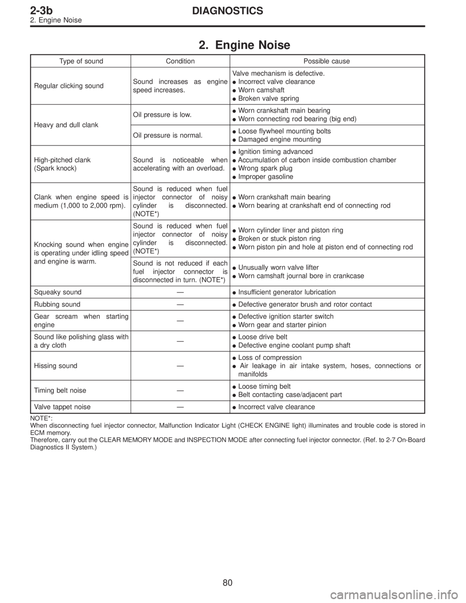
2. Engine Noise
Type of sound Condition Possible cause
Regular clicking soundSound increases as engine
speed increases.Valve mechanism is defective.
�Incorrect valve clearance
�Worn camshaft
�Broken valve spring
Heavy and dull clankOil pressure is low.�Worn crankshaft main bearing
�Worn connecting rod bearing (big end)
Oil pressure is normal.�Loose flywheel mounting bolts
�Damaged engine mounting
High-pitched clank
(Spark knock)Sound is noticeable when
accelerating with an overload.�Ignition timing advanced
�Accumulation of carbon inside combustion chamber
�Wrong spark plug
�Improper gasoline
Clank when engine speed is
medium (1,000 to 2,000 rpm).Sound is reduced when fuel
injector connector of noisy
cylinder is disconnected.
(NOTE*)�Worn crankshaft main bearing
�Worn bearing at crankshaft end of connecting rod
Knocking sound when engine
is operating under idling speed
and engine is warm.Sound is reduced when fuel
injector connector of noisy
cylinder is disconnected.
(NOTE*)�Worn cylinder liner and piston ring
�Broken or stuck piston ring
�Worn piston pin and hole at piston end of connecting rod
Sound is not reduced if each
fuel injector connector is
disconnected in turn. (NOTE*)�Unusually worn valve lifter
�Worn camshaft journal bore in crankcase
Squeaky sound—�Insufficient generator lubrication
Rubbing sound—�Defective generator brush and rotor contact
Gear scream when starting
engine—�Defective ignition starter switch
�Worn gear and starter pinion
Sound like polishing glass with
a dry cloth—�Loose drive belt
�Defective engine coolant pump shaft
Hissing sound—�Loss of compression
�Air leakage in air intake system, hoses, connections or
manifolds
Timing belt noise—�Loose timing belt
�Belt contacting case/adjacent part
Valve tappet noise—�Incorrect valve clearance
NOTE*:
When disconnecting fuel injector connector, Malfunction Indicator Light (CHECK ENGINE light) illuminates and trouble code is stored in
ECM memory.
Therefore, carry out the CLEAR MEMORY MODE and INSPECTION MODE after connecting fuel injector connector. (Ref. to 2-7 On-Board
Diagnostics II System.)
80
2-3bDIAGNOSTICS
2. Engine Noise
Page 615 of 3342
3. Transmission
A: REMOVAL
1. Open front hood fully, and support it with stay.
2. Disconnect battery ground terminal.
3. Remove air intake duct and chamber.
4. Disconnect connectors and cables.
5. Remove starter.
6. Remove pitching stopper.
AT model
7. Separate torque converter from drive plate.
8. Remove ATF level gauge.
9. Remove transmission connector bracket.
Hydraulic clutch model
10. Remove operating cylinder.
11. Set special tools.
12. Remove bolt which holds right upper side of transmission to
engine.
Hydraulic clutch model
13. Remove clutch damper.
14. Remove exhaust system.
�Front exhaust pipe
�Center exhaust pipe
�Rear exhaust pipe [AWD]
AT model
15. Drain ATF to remove ATF drain plug.
16. Disconnect ATF cooler hose from pipe on transmission side,
and remove ATF level gauge guide.
AWD model
17. Remove propeller shaft.
�A
�
�
�
�
�
�
�
�
�
�
�
�
�
�
27
2-11SERVICE PROCEDURE
3. Transmission
Page 618 of 3342
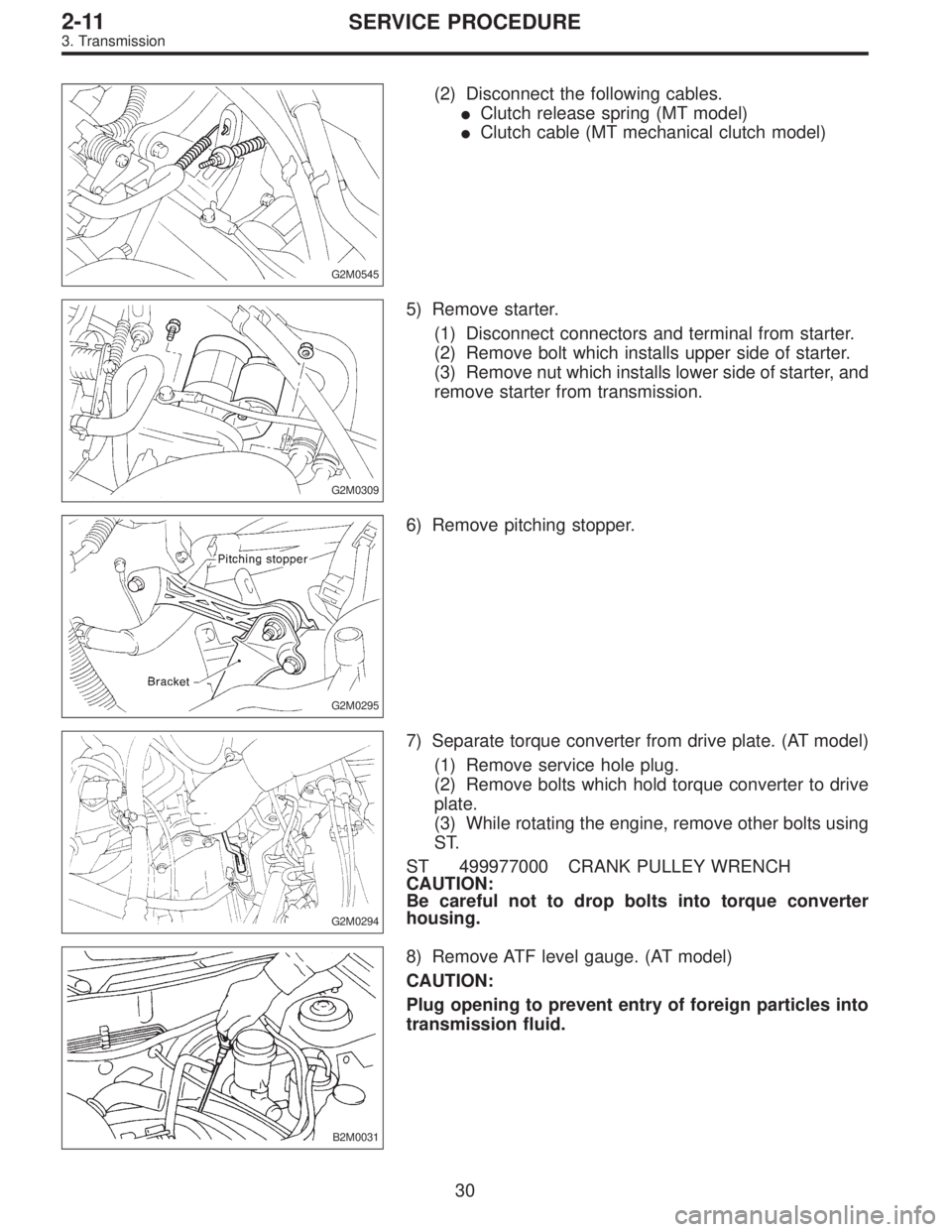
G2M0545
(2) Disconnect the following cables.
�Clutch release spring (MT model)
�Clutch cable (MT mechanical clutch model)
G2M0309
5) Remove starter.
(1) Disconnect connectors and terminal from starter.
(2) Remove bolt which installs upper side of starter.
(3) Remove nut which installs lower side of starter, and
remove starter from transmission.
G2M0295
6) Remove pitching stopper.
G2M0294
7) Separate torque converter from drive plate. (AT model)
(1) Remove service hole plug.
(2) Remove bolts which hold torque converter to drive
plate.
(3) While rotating the engine, remove other bolts using
ST.
ST 499977000 CRANK PULLEY WRENCH
CAUTION:
Be careful not to drop bolts into torque converter
housing.
B2M0031
8) Remove ATF level gauge. (AT model)
CAUTION:
Plug opening to prevent entry of foreign particles into
transmission fluid.
30
2-11SERVICE PROCEDURE
3. Transmission
Page 626 of 3342
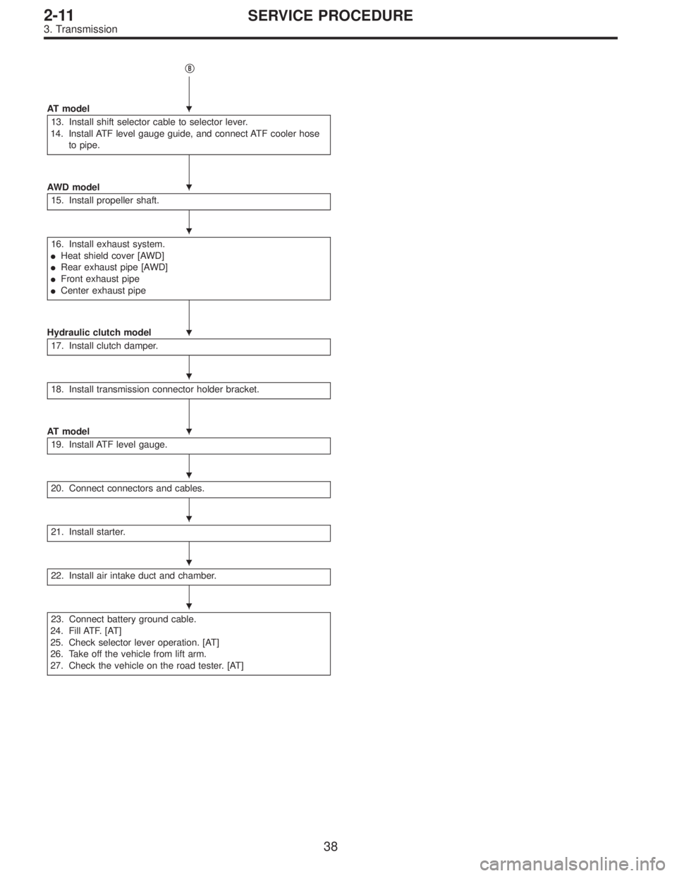
�B
AT model
13. Install shift selector cable to selector lever.
14. Install ATF level gauge guide, and connect ATF cooler hose
to pipe.
AWD model
15. Install propeller shaft.
16. Install exhaust system.
�Heat shield cover [AWD]
�Rear exhaust pipe [AWD]
�Front exhaust pipe
�Center exhaust pipe
Hydraulic clutch model
17. Install clutch damper.
18. Install transmission connector holder bracket.
AT model
19. Install ATF level gauge.
20. Connect connectors and cables.
21. Install starter.
22. Install air intake duct and chamber.
23. Connect battery ground cable.
24. Fill ATF. [AT]
25. Check selector lever operation. [AT]
26. Take off the vehicle from lift arm.
27. Check the vehicle on the road tester. [AT]
�
�
�
�
�
�
�
�
�
�
38
2-11SERVICE PROCEDURE
3. Transmission
Page 633 of 3342
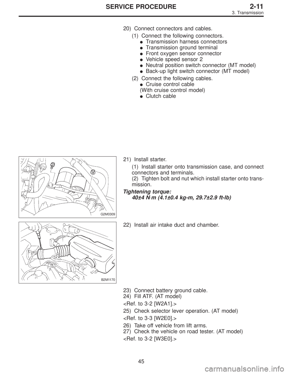
20) Connect connectors and cables.
(1) Connect the following connectors.
�Transmission harness connectors
�Transmission ground terminal
�Front oxygen sensor connector
�Vehicle speed sensor 2
�Neutral position switch connector (MT model)
�Back-up light switch connector (MT model)
(2) Connect the following cables.
�Cruise control cable
(With cruise control model)
�Clutch cable
G2M0309
21) Install starter.
(1) Install starter onto transmission case, and connect
connectors and terminals.
(2) Tighten bolt and nut which install starter onto trans-
mission.
Tightening torque:
40±4 N⋅m (4.1±0.4 kg-m, 29.7±2.9 ft-lb)
B2M1170
22) Install air intake duct and chamber.
23) Connect battery ground cable.
24) Fill ATF. (AT model)
25) Check selector lever operation. (AT model)
26) Take off vehicle from lift arms.
27) Check the vehicle on road tester. (AT model)
45
2-11SERVICE PROCEDURE
3. Transmission
Page 734 of 3342
G3M0291
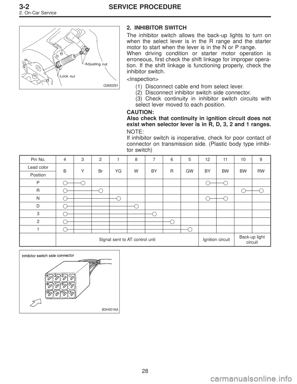
2. INHIBITOR SWITCH
The inhibitor switch allows the back-up lights to turn on
when the select lever is in the R range and the starter
motor to start when the lever is in the N or P range.
When driving condition or starter motor operation is
erroneous, first check the shift linkage for improper opera-
tion. If the shift linkage is functioning properly, check the
inhibitor switch.
(1) Disconnect cable end from select lever.
(2) Disconnect inhibitor switch side connector.
(3) Check continuity in inhibitor switch circuits with
select lever moved to each position.
CAUTION:
Also check that continuity in ignition circuit does not
exist when selector lever is in R, D, 3, 2 and 1 ranges.
NOTE:
If inhibitor switch is inoperative, check for poor contact of
connector on transmission side. (Plastic body type inhibi-
tor switch)
PinNo. 432187651211109
Lead color
B Y Br YG W BY R GW BY BW BW RW
Position
P��
��
R����
N����
D��
3��
2��
1��
Signal sent to AT control unit Ignition circuitBack-up light
circuit
B3H0016A
28
3-2SERVICE PROCEDURE
2. On-Car Service
Page 834 of 3342
G3M0291
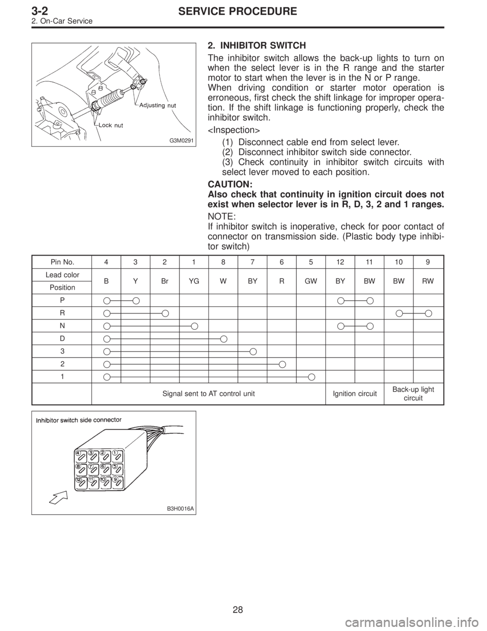
2. INHIBITOR SWITCH
The inhibitor switch allows the back-up lights to turn on
when the select lever is in the R range and the starter
motor to start when the lever is in the N or P range.
When driving condition or starter motor operation is
erroneous, first check the shift linkage for improper opera-
tion. If the shift linkage is functioning properly, check the
inhibitor switch.
(1) Disconnect cable end from select lever.
(2) Disconnect inhibitor switch side connector.
(3) Check continuity in inhibitor switch circuits with
select lever moved to each position.
CAUTION:
Also check that continuity in ignition circuit does not
exist when selector lever is in R, D, 3, 2 and 1 ranges.
NOTE:
If inhibitor switch is inoperative, check for poor contact of
connector on transmission side. (Plastic body type inhibi-
tor switch)
PinNo. 432187651211109
Lead color
B Y Br YG W BY R GW BY BW BW RW
Position
P��
��
R����
N����
D��
3��
2��
1��
Signal sent to AT control unit Ignition circuitBack-up light
circuit
B3H0016A
28
3-2SERVICE PROCEDURE
2. On-Car Service