Page 2645 of 3342
8C7CHECK POOR CONTACT IN CONNEC-
TOR BETWEEN ABSCM AND ABS SEN-
SOR.
: Is there poor contact in connectors between
ABSCM and ABS sensor?
: Repair connector.
: Go to step8C8.
8C8
CHECK SOURCES OF SIGNAL NOISE.
: Is the car telephone or the wireless trans-
mitter properly installed?
: Go to next.
: Properly install the car telephone or the wireless
transmitter.
: Are noise sources (such as an antenna)
installed near the sensor harness?
: Install the noise sources apart from the sensor
harness.
: Go to step8C9.
B4M1038A
8C9
CHECK SHIELD CIRCUIT.
1) Connect all connectors.
2) Measure resistance between shield connector and
chassis ground.
: Trouble code/Connector & terminal
22/(B100) No. 11—Chassis ground
24/(B100) No. 2—Chassis ground
26/(P1) No. 8—Chassis ground
28/(P1) No. 3—Chassis ground
Is resistance less than 0.5Ω?
: Go to step8C10.
: Repair shield harness.
40
4-4cBRAKES [ABS 5.3 TYPE]
8. Diagnostics Chart with Trouble Code
Page 2665 of 3342
B4M0838A
8G1
CHECK GROUND CIRCUIT OF ABSCM.
1) Turn ignition switch to OFF.
2) Disconnect connector from ABSCM.
3) Measure resistance between ABSCM and chassis
ground.
: Connector & terminal
(F49) No. 1—Chassis ground
(F49) No. 55—Chassis ground
Is resistance less than 0.5Ω?
: Go to step8G2.
: Repair ABSCM ground harness.
8G2CHECK POOR CONTACT IN CONNEC-
TORS BETWEEN BATTERY, IGNITION
SWITCH AND ABSCM.
: Is there poor contact in connectors between
battery, ignition switch and ABSCM?
: Repair connector.
: Go to step8G3.
8G3
CHECK SOURCES OF SIGNAL NOISE.
: Is the car telephone or the wireless trans-
mitter properly installed?
: Go to next.
: Properly install the car telephone or the wireless
transmitter.
: Are noise sources (such as an antenna)
installed near the sensor harness?
: Install the noise sources apart from the sensor
harness.
: Go to step8G4.
60
4-4cBRAKES [ABS 5.3 TYPE]
8. Diagnostics Chart with Trouble Code
Page 2749 of 3342

B4M0922
10L1CHECK OUTPUT OF ABS SENSOR
USING SELECT MONITOR.
Read the ABS sensor output corresponding to the faulty
system in the select monitor function mode.
NOTE:
The select monitor display shows that the front right wheel
is rotating at 30 km/h.
: Does the speed indicated on the display
change in response to the speedometer
reading during acceleration/deceleration
when the steering wheel is in the straight-
ahead position?
: Go to step10L2.
: Go to step10L3.
10L2CHECK POOR CONTACT IN CONNEC-
TOR BETWEEN ABSCM AND ABS SEN-
SOR.
: Is there poor contact in connectors between
ABSCM and ABS sensor?
: Repair connector.
: Go to step10L3.
10L3
CHECK SOURCES OF SIGNAL NOISE.
: Is the car telephone or the wireless trans-
mitter properly installed?
: Go to next.
: Properly install the car telephone or the wireless
transmitter.
: Are noise sources (such as an antenna)
installed near the sensor harness?
: Install the noise sources apart from the sensor
harness.
: Go to step10L4.
144
4-4cBRAKES [ABS 5.3 TYPE]
10. Diagnostics Chart with Select Monitor
Page 2755 of 3342
10L13
CHECK SOURCES OF SIGNAL NOISE.
: Is the car telephone or the wireless trans-
mitter properly installed?
: Go to next.
: Properly install the car telephone or the wireless
transmitter.
: Are noise sources (such as an antenna)
installed near the sensor harness?
: Install the noise sources apart from the sensor
harness.
: Go to step10L14.
B4M1038A
10L14
CHECK SHIELD CIRCUIT.
1) Connect all connectors.
2) Measure resistance between shield connector and
chassis ground.
: Trouble code/Connector & terminal
22/(B100) No. 11—Chassis ground
24/(B100) No. 2—Chassis ground
26/(P1) No. 8—Chassis ground
28/(P1) No. 3—Chassis ground
Is resistance less than 0.5Ω?
: Go to step10L15.
: Repair shield harness.
150
4-4cBRAKES [ABS 5.3 TYPE]
10. Diagnostics Chart with Select Monitor
Page 2787 of 3342
B4M0838A
10V1
CHECK GROUND CIRCUIT OF ABSCM.
1) Turn ignition switch to OFF.
2) Disconnect connector from ABSCM.
3) Measure resistance between ABSCM and chassis
ground.
: Connector & terminal
(F49) No. 1—Chassis ground
(F49) No. 55—Chassis ground
Is resistance less than 0.5Ω?
: Go to step10V2.
: Repair ABSCM ground harness.
10V2CHECK POOR CONTACT IN CONNEC-
TORS BETWEEN BATTERY, IGNITION
SWITCH AND ABSCM.
: Is there poor contact in connectors between
battery, ignition switch and ABSCM?
: Repair connector.
: Go to step10V3.
10V3
CHECK SOURCES OF SIGNAL NOISE.
: Is the car telephone or the wireless trans-
mitter properly installed?
: Go to next.
: Properly install the car telephone or the wireless
transmitter.
: Are noise sources (such as an antenna)
installed near the sensor harness?
: Install the noise sources apart from the sensor
harness.
: Go to step10V4.
182
4-4cBRAKES [ABS 5.3 TYPE]
10. Diagnostics Chart with Select Monitor
Page 2916 of 3342
![SUBARU LEGACY 1997 Service Repair Manual 8I14CHECK POOR CONTACT IN CONNEC-
TORS.
: Is there poor contact in connectors between
ABSCM&H/U and ABS sensor? <Ref. to
FOREWORD [T3C1].>
: Repair connector.
: Go to step8I15.
8I15
CHECK SOURCES OF S SUBARU LEGACY 1997 Service Repair Manual 8I14CHECK POOR CONTACT IN CONNEC-
TORS.
: Is there poor contact in connectors between
ABSCM&H/U and ABS sensor? <Ref. to
FOREWORD [T3C1].>
: Repair connector.
: Go to step8I15.
8I15
CHECK SOURCES OF S](/manual-img/17/57434/w960_57434-2915.png)
8I14CHECK POOR CONTACT IN CONNEC-
TORS.
: Is there poor contact in connectors between
ABSCM&H/U and ABS sensor?
FOREWORD [T3C1].>
: Repair connector.
: Go to step8I15.
8I15
CHECK SOURCES OF SIGNAL NOISE.
: Is the car telephone or the wireless trans-
mitter properly installed?
: Go to step8I16.
: Properly install the car telephone or the wireless
transmitter.
8I16
CHECK SOURCES OF SIGNAL NOISE.
: Are noise sources (such as an antenna)
installed near the sensor harness?
: Install the noise sources apart from the sensor
harness.
: Go to step8I17.
B4M1244A
8I17
CHECK SHIELD CIRCUIT.
1) Connect all connectors.
2) Measure resistance between shield connector and
chassis ground.
Connector & terminal
Trouble code 22 / (B100) No. 11—Chassis ground:
Trouble code 24 / (B100) No. 2—Chassis ground:
Trouble code 26 / Go to step 8I18.
Trouble code 28 / Go to step 8I18.
: Is the resistance less than 0.5Ω?
: Go to step8I18.
: Repair shield harness.
40
4-4dBRAKES [ABS 5.3i TYPE]
8. Diagnostics Chart with Trouble Code by ABS Warning Light
Page 2930 of 3342

B4M1243A
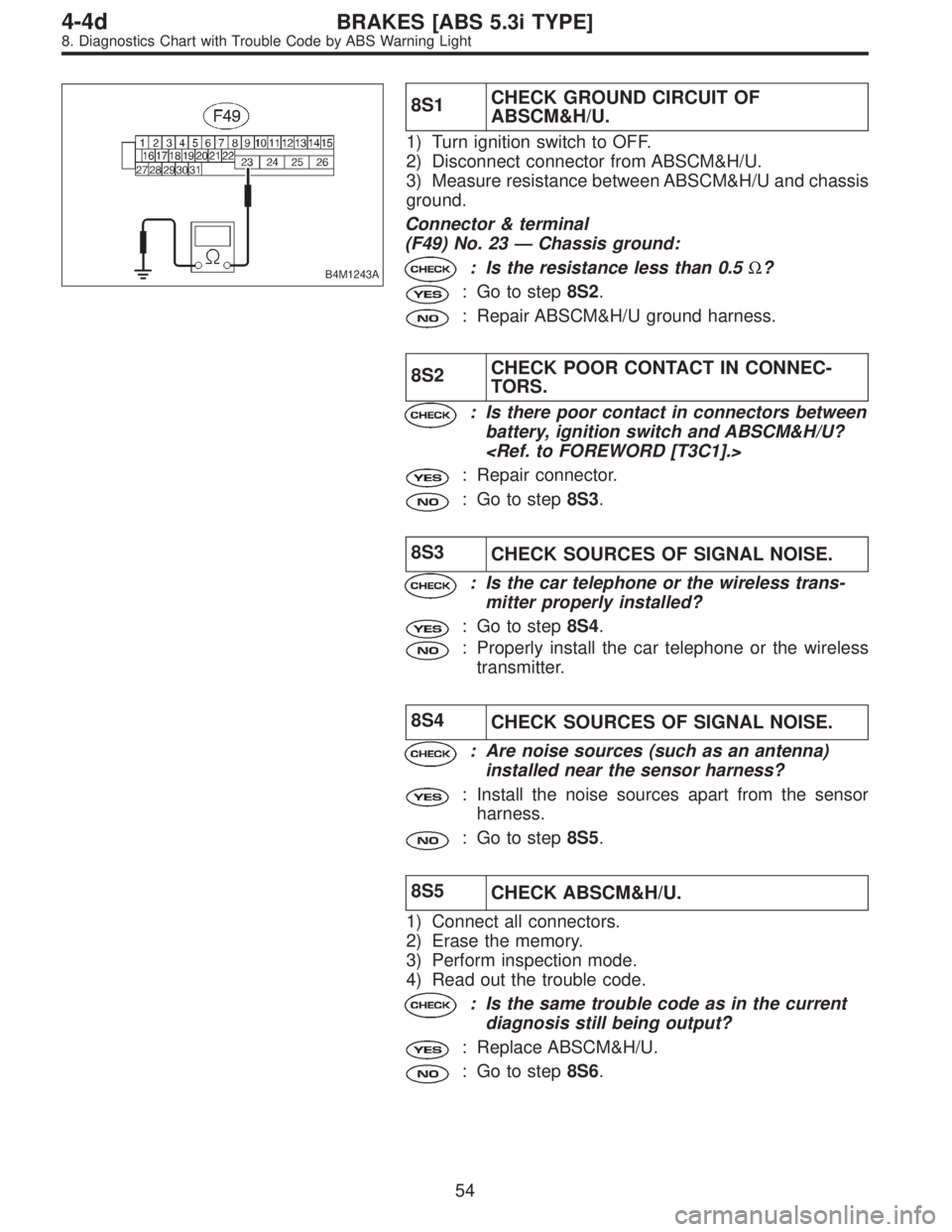
8S1CHECK GROUND CIRCUIT OF
ABSCM&H/U.
1) Turn ignition switch to OFF.
2) Disconnect connector from ABSCM&H/U.
3) Measure resistance between ABSCM&H/U and chassis
ground.
Connector & terminal
(F49) No. 23—Chassis ground:
: Is the resistance less than 0.5Ω?
: Go to step8S2.
: Repair ABSCM&H/U ground harness.
8S2CHECK POOR CONTACT IN CONNEC-
TORS.
: Is there poor contact in connectors between
battery, ignition switch and ABSCM&H/U?
: Repair connector.
: Go to step8S3.
8S3
CHECK SOURCES OF SIGNAL NOISE.
: Is the car telephone or the wireless trans-
mitter properly installed?
: Go to step8S4.
: Properly install the car telephone or the wireless
transmitter.
8S4
CHECK SOURCES OF SIGNAL NOISE.
: Are noise sources (such as an antenna)
installed near the sensor harness?
: Install the noise sources apart from the sensor
harness.
: Go to step8S5.
8S5
CHECK ABSCM&H/U.
1) Connect all connectors.
2) Erase the memory.
3) Perform inspection mode.
4) Read out the trouble code.
: Is the same trouble code as in the current
diagnosis still being output?
: Replace ABSCM&H/U.
: Go to step8S6.
54
4-4dBRAKES [ABS 5.3i TYPE]
8. Diagnostics Chart with Trouble Code by ABS Warning Light
Page 2987 of 3342

B4M0922
10L1CHECK OUTPUT OF ABS SENSOR
USING SELECT MONITOR.
Read the ABS sensor output corresponding to the faulty
system in the select monitor function mode.
NOTE:
The select monitor display shows that the front right wheel
is rotating at 30 km/h.
: Does the speed indicated on the display
change in response to the speedometer
reading during acceleration/deceleration
when the steering wheel is in the straight-
ahead position?
: Go to step10L2.
: Go to step10L8.
10L2CHECK POOR CONTACT IN CONNEC-
TORS.
Turn ignition switch to OFF.
: Is there poor contact in connectors between
ABSCM&H/U and ABS sensor?
: Repair connector.
: Go to step10L3.
10L3
CHECK SOURCES OF SIGNAL NOISE.
: Is the car telephone or the wireless trans-
mitter properly installed?
: Go to step10L4.
: Properly install the car telephone or the wireless
transmitter.
10L4
CHECK SOURCES OF SIGNAL NOISE.
: Are noise sources (such as an antenna)
installed near the sensor harness?
: Install the noise sources apart from the sensor
harness.
: Go to step10L5.
111
4-4dBRAKES [ABS 5.3i TYPE]
10. Diagnostics Chart with Select Monitor