Page 1815 of 3342
C: DIAGNOSTICS PROCEDURE No. 1
Check that stop lights do not remain on when brake
pedal is released.
OK
�Not OK
Check stop light system.
Disconnect connector from shift lock control module.
Check that shift lock does not occur when shift lever
is moved to“P”.
OK
�Not OK
Replace shift lock control module.
Disconnect connector from“P”position switch.
Disconnect connector from shift lock solenoid.
Check that shift lock does not occur when shift lever
is moved to“P”.
OK
�Not OK
Short in wiring harness of shift lock solenoid.
Check selector lever assembly.
�
�
�
�
�
�
70
6-2DIAGNOSTICS
2. AT Shift Lock System
Page 2469 of 3342

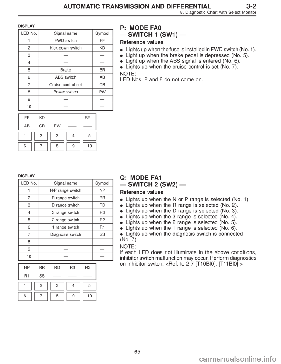
DISPLAY
LED No. Signal name Symbol
1 FWD switch FF
2 Kick-down switch KD
3——
4——
5 Brake BR
6 ABS switch AB
7 Cruise control set CR
8 Power switch PW
9——
10——
FF KD—— ——BR
AB CR PW—— ——
1
2345
678910
P: MODE FA0
—SWITCH 1 (SW1)—
Reference values
�Lights up when the fuse is installed in FWD switch (No. 1).
�Light up when the brake pedal is depressed (No. 5).
�Light up when the ABS signal is entered (No. 6).
�Lights up when the cruise control is set (No. 7).
NOTE:
LED Nos. 2 and 8 do not come on.
DISPLAY
LED No. Signal name Symbol
1 N/P range switch NP
2 R range switch RR
3 D range switch RD
4 3 range switch R3
5 2 range switch R2
6 1 range switch R1
7 Diagnosis switch SS
8——
9——
10——
NP RR RD R3 R2
R1 SS—— —— ——
1
2345
678910
Q: MODE FA1
—SWITCH 2 (SW2)—
Reference values
�Lights up when the N or P range is selected (No. 1).
�Lights up when the R range is selected (No. 2).
�Lights up when the D range is selected (No. 3).
�Lights up when the 3 range is selected (No. 4).
�Lights up when the 2 range is selected (No. 5).
�Lights up when the 1 range is selected (No. 6).
�Lights up when the diagnosis switch is connected
(No. 7).
NOTE:
If each LED does not illuminate in the above conditions,
inhibitor switch malfunction may occur. Perform diagnostics
on inhibitor switch.
65
3-2AUTOMATIC TRANSMISSION AND DIFFERENTIAL
8. Diagnostic Chart with Select Monitor
Page 2490 of 3342

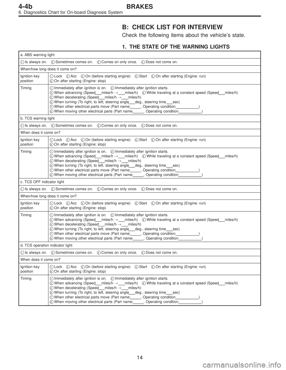
B: CHECK LIST FOR INTERVIEW
Check the following items about the vehicle’s state.
1. THE STATE OF THE WARNING LIGHTS
a. ABS warning light
�
1Is always on.�2Sometimes comes on.�3Comes on only once.�4Does not come on.
When/how long does it come on?
Ignition key
position�
1Lock�2Acc�3On (before starting engine)�4Start�5On after starting (Engine: run)
�6On after starting (Engine: stop)
Timing�
1Immediately after ignition is on.�2Immediately after ignition starts.
�3When advancing (Speedmiles/h,miles/h)�4While traveling at a constant speed (Speedmiles/h)
�5When decelerating (Speedmiles/h,miles/h)
�6When turning (To right, to left, steering angledeg., steering timesec)
�7When other electrical parts move (Part name:, Operating condition)
�8When moving other electrical parts (Part name:, Operating condition)
b. TCS warning light
�
1Is always on.�2Sometimes comes on.�3Comes on only once.�4Does not come on.
When does it come on?
Ignition key
position�
1Lock�2Acc�3On (before starting engine)�4Start�5On after starting (Engine: run)
�6On after starting (Engine: stop)
Timing�
1Immediately after ignition is on.�2Immediately after ignition starts.
�3When advancing (Speedmiles/h,miles/h)�4While traveling at a constant speed (Speedmiles/h)
�5When decelerating (Speedmiles/h,miles/h)
�6When turning (To right, to left, steering angledeg., steering timesec)
�7When other electrical parts move (Part name:, Operating condition)
�8When moving other electrical parts (Part name:, Operating condition)
c. TCS OFF indicator light
�
1Is always on.�2Sometimes comes on.�3Comes on only once.�4Does not come on.
When/how long does it come on?
Ignition key
position�
1Lock�2Acc�3On (before starting engine)�4Start�5On after starting (Engine: run)
�6On after starting (Engine: stop)
Timing�
1Immediately after ignition is on.�2Immediately after ignition starts.
�3When advancing (Speedmiles/h,miles/h)�4While traveling at a constant speed (Speedmiles/h)
�5When decelerating (Speedmiles/h,miles/h)
�6When turning (To right, to left, steering angledeg., steering timesec)
�7When other electrical parts move (Part name:, Operating condition)
�8When moving other electrical parts (Part name:, Operating condition)
d. TCS operation indicator light
�
1Is always on.�2Sometimes comes on.�3Comes on only once.�4Does not come on.
When does it come on?
Ignition key
position�
1Lock�2Acc�3On (before starting engine)�4Start�5On after starting (Engine: run)
�6On after starting (Engine: stop)
Timing�
1Immediately after ignition is on.�2Immediately after ignition starts.
�3When advancing (Speedmiles/h,miles/h)�4While traveling at a constant speed (Speedmiles/h)
�5When decelerating (Speedmiles/h,miles/h)
�6When turning (To right, to left, steering angledeg., steering timesec)
�7When other electrical parts move (Part name:, Operating condition)
�8When moving other electrical parts (Part name:, Operating condition)
14
4-4bBRAKES
6. Diagnostics Chart for On-board Diagnosis System
Page 2496 of 3342
B: ABS AND TCS WARNING LIGHT DO NOT
GO OFF.
—TCS OFF AND TCS OPERATING
INDICATOR LIGHTS COME ON AND GO OFF
PROPERLY WHEN STARTING THE ENGINE,
WHILE ABS WARNING AND TCS WARNING
LIGHTS KEEP ON.—
1. Check brake fluid level.
OK
�Not OK
Add to brake fluid.
2. Check brake fluid level sensor.
OK
�Not OK
Replace master cylinder.
3. Check harness connector between ABS/TCS
control module and alternator.
OK
�Not OK
Replace harness connector.
Replace ABS/TCS control module.
B4M0389
�
�
�
20
4-4bBRAKES
7. Diagnostics Chart for Warning Light Circuit Failure
Page 2498 of 3342
C: TCS WARNING LIGHT AND TCS
INDICATOR OFF AND TCS OPERATING
INDICATOR LIGHTS COME ON AND GO OFF
PROPERLY, WHILE ABS WARNING LIGHT
DOES NOT GO OFF.
—TCS WARNING LIGHT AND TCS OFF
INDICATOR AND TCS OPERATING
INDICATOR LIGHTS COME ON AND GO OFF
PROPERLY WHEN STARTING THE ENGINE,
WHILE ABS WARNING LIGHT DOES NOT GO
OFF.—
1. Check harness connector between ABS/TCS
control module and ABS warning light.�Repair harness connector.
Replace ABS/TCS control module.
B4M0392
�
22
4-4bBRAKES
7. Diagnostics Chart for Warning Light Circuit Failure
Page 2502 of 3342
E: TCS OFF INDICATOR LIGHT DOES NOT
GO OFF.
—ABS WARNING, TCS WARNING AND TCS
OPERATING INDICATOR LIGHTS COME ON
AND GO OFF PROPERLY WHEN STARTING
THE ENGINE, BUT TCS OFF INDICATOR
DOES NOT GO OFF FOR MORE THAN 30
SECONDS AFTER ENGINE RUNNING.—
Does malfunction indicator lamp (Check engine
lamp) come on?
No
�Ye s
Conduct OBD II diagnosis.
1. Check harness connector between ABS/TCS
control module and TCS OFF indicator light.
OK
�Not OK
Repair harness/connector.
Replace ABS/TCS control module.
B4M0396
�
�
26
4-4bBRAKES
7. Diagnostics Chart for Warning Light Circuit Failure
Page 2504 of 3342
F: TCS OPERATING INDICATOR LIGHT DOES
NOT GO OFF.
—WHEN STARTING THE ENGINE, ABS
WARNING, TCS WARNING AND TCS OFF
INDICATOR LIGHTS COME ON AND GO OFF
PROPERLY BUT TCS OPERATING
INDICATOR LIGHT ONLY KEEPS ON.—
1. Check harness connector between ABS/TCS
control module and TCS operating indicator
light.
OK
�Not OK
Repair harness/connector.
Replace ABS/TCS control module.
B4M0398
�
28
4-4bBRAKES
7. Diagnostics Chart for Warning Light Circuit Failure
Page 2508 of 3342
H: ABS WARNING, TCS WARNING, TCS
OPERATING INDICATOR AND/OR TCS OFF
INDICATOR LIGHTS DO NOT COME ON.
—TROUBLE IN WARNING LIGHT DRIVE
CIRCUIT—
DIAGNOSIS:
�Faulty ABS warning light
�Faulty TCS warning light
�Faulty TCS OFF light
�Faulty TCS operating indicator light
�Faulty harness connector
�Faulty ABS/TCS control module
TROUBLE SYMPTOM:
�Warning light does not illuminate.
�Impossible to read trouble code.
Check warning light bulb.
OK
�Not OK
Repair warning light bulb.
1. Check warning light power supply.
OK
�Not OK
Repair ABS warning light power line.
2. Check input voltage of ABS/TCS control mod-
ule.
OK
�Not OK
Repair harness/connector.
3. Check ground line of ABS/TCS control mod-
ule.
OK
�Not OK
Repair ground line.
Replace ABS/TCS control module.
�
�
�
�
32
4-4bBRAKES
7. Diagnostics Chart for Warning Light Circuit Failure