Page 2947 of 3342

8X1
CHECK STOP LIGHTS COME ON.
Depress the brake pedal.
: Do stop lights come on?
: Go to step8X2.
: Repair stop lights circuit.
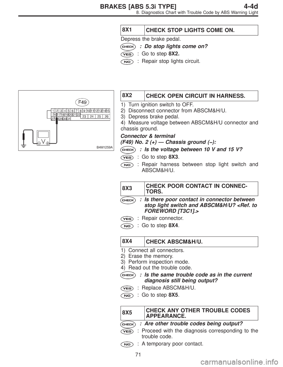
B4M1259A
8X2
CHECK OPEN CIRCUIT IN HARNESS.
1) Turn ignition switch to OFF.
2) Disconnect connector from ABSCM&H/U.
3) Depress brake pedal.
4) Measure voltage between ABSCM&H/U connector and
chassis ground.
Connector & terminal
(F49) No. 2 (+)—Chassis ground (�):
: Is the voltage between 10 V and 15 V?
: Go to step8X3.
: Repair harness between stop light switch and
ABSCM&H/U.
8X3CHECK POOR CONTACT IN CONNEC-
TORS.
: Is there poor contact in connector between
stop light switch and ABSCM&H/U?
FOREWORD [T3C1].>
: Repair connector.
: Go to step8X4.
8X4
CHECK ABSCM&H/U.
1) Connect all connectors.
2) Erase the memory.
3) Perform inspection mode.
4) Read out the trouble code.
: Is the same trouble code as in the current
diagnosis still being output?
: Replace ABSCM&H/U.
: Go to step8X5.
8X5CHECK ANY OTHER TROUBLE CODES
APPEARANCE.
: Are other trouble codes being output?
: Proceed with the diagnosis corresponding to the
trouble code.
: A temporary poor contact.
71
4-4dBRAKES [ABS 5.3i TYPE]
8. Diagnostics Chart with Trouble Code by ABS Warning Light
Page 3038 of 3342
B4M0973
10AF1CHECK OUTPUT OF STOP LIGHT
SWITCH USING SELECT MONITOR.
1) Press [F], [0] and [9] on the select monitor.
2) Depress the brake pedal.
3) Read the stop light switch output on the select monitor
display.
: Is the reading indicated on monitor display
less than 1.5 V?
: Go to step10AF2.
: Go to step10AF3.
B4M1265
10AF2CHECK OUTPUT OF STOP LIGHT
SWITCH USING SELECT MONITOR.
1) Release the brake pedal.
2) Read the stop light switch output on the select monitor
display.
: Is the reading indicated on monitor display
between 10 V and 15 V?
: Go to step10AF5.
: Go to step10AF3.
10AF3
CHECK IF STOP LIGHTS COME ON.
Depress the brake pedal.
: Do stop lights turn on?
: Go to step10AF4.
: Repair stop lights circuit.
162
4-4dBRAKES [ABS 5.3i TYPE]
10. Diagnostics Chart with Select Monitor
Page 3164 of 3342

LED No. Signal name Display
1 SET/COAST switch SE
2 RESUME/ACCEL switch RE
3 Stop light switch ST
4�Brake switch
�Clutch switch (MT)BR
5 Inhibitor switch (AT) N
6——
7——
8——
9——
10——
SE RE ST BR N
—————
1
2345
678910
1. CHECK THE SIGNAL USING A SELECT MONITOR.
1) Turn ignition switch to ON.
2) Turn cruise control main switch to ON.
3) Set select monitor in“FA 0”mode.
4) Check signals for proper operation.
(1) When pushing the SET switch:
LED No. 1 goes out—lights.
(2) When pushing the RESUME switch:
LED No. 2 goes out—lights.
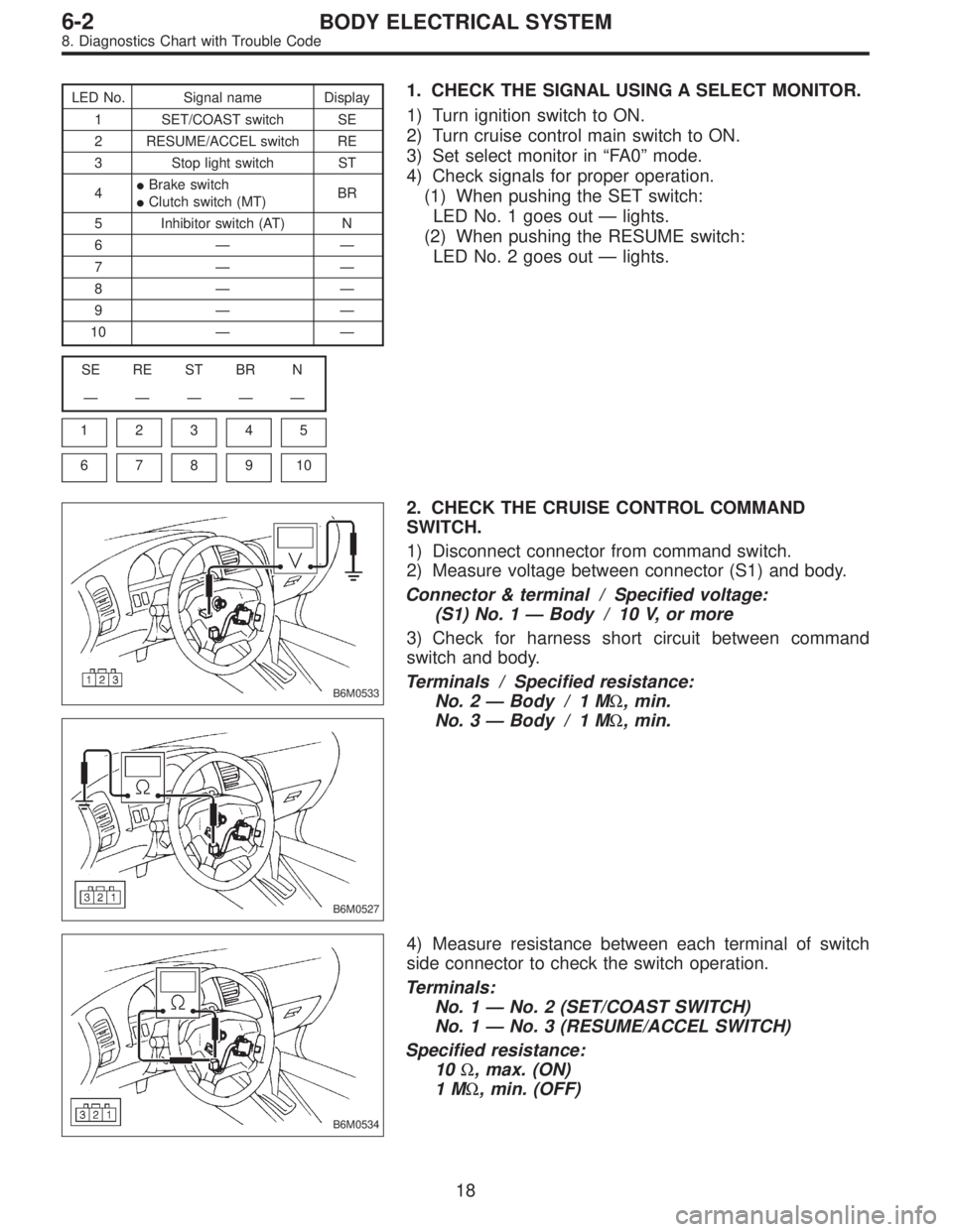
B6M0533
B6M0527
2. CHECK THE CRUISE CONTROL COMMAND
SWITCH.
1) Disconnect connector from command switch.
2) Measure voltage between connector (S1) and body.
Connector & terminal / Specified voltage:
(S1) No. 1—Body / 10 V, or more
3) Check for harness short circuit between command
switch and body.
Terminals / Specified resistance:
No. 2—Body / 1 MΩ, min.
No. 3—Body / 1 MΩ, min.
B6M0534
4) Measure resistance between each terminal of switch
side connector to check the switch operation.
Terminals:
No. 1—No. 2 (SET/COAST SWITCH)
No. 1—No. 3 (RESUME/ACCEL SWITCH)
Specified resistance:
10Ω, max. (ON)
1MΩ, min. (OFF)
18
6-2BODY ELECTRICAL SYSTEM
8. Diagnostics Chart with Trouble Code
Page 3166 of 3342

LED No. Signal name Display
1 SET/COAST switch SE
2 RESUME/ACCEL switch RE
3 Stop light switch ST
4�Brake switch
�Clutch switch (MT)BR
5 Inhibitor switch (AT) N
6——
7——
8——
9——
10——
SE RE ST BR N
—————
1
2345
678910
1. CHECK THE SIGNAL USING A SELECT MONITOR.
1) Turn ignition switch to ON.
2) Turn cruise control main switch to ON.
3) Apply parking brake securely.
4) Set select monitor in“FA 0”mode.
5) Release the clutch pedal. (MT model)
6) Depress the brake pedal and check signals for proper
operation.
Stop light switch: LED No. 3 goes out—lights.
Brake switch : LED No. 4 goes out—lights.
7) Release the brake pedal.
8) Depress the clutch pedal and check signal for proper
operation. (MT model)
Clutch switch: LED No. 4 goes out—lights.
9) Set the selector lever from D to N position and check
signal for proper operation. (AT model)
Inhibitor switch: LED No. 5 goes out—lights.
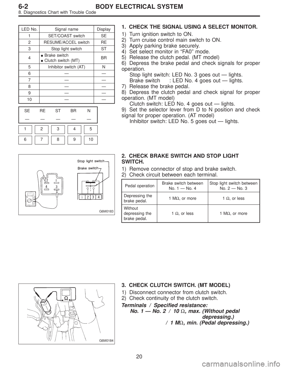
G6M0183
2. CHECK BRAKE SWITCH AND STOP LIGHT
SWITCH.
1) Remove connector of stop and brake switch.
2) Check circuit between each terminal.
Pedal operationBrake switch between
No. 1—No. 4Stop light switch between
No. 2—No. 3
Depressing the
brake pedal.1MΩ,ormore 1Ω, or less
Without
depressing the
brake pedal.1Ω, or less 1 MΩ,ormore
G6M0184
3. CHECK CLUTCH SWITCH. (MT MODEL)
1) Disconnect connector from clutch switch.
2) Check continuity of the clutch switch.
Terminals / Specified resistance:
No. 1—No. 2 / 10Ω, max. (Without pedal
depressing.)
/1MΩ, min. (Pedal depressing.)
20
6-2BODY ELECTRICAL SYSTEM
8. Diagnostics Chart with Trouble Code