Page 3135 of 3342

M: TROUBLE CODE 43
DIAGNOSIS:
�Airbag main harness circuit (Driver) is shorted to power
supply.
�Airbag module harness (Driver) is shorted to power sup-
ply.
�Roll connector is shorted to power supply.
�Airbag control module is faulty.
1. Airbag main harness inspection
CAUTION:
Before performing diagnostics on airbag system, turn
ignition switch“OFF”, disconnect battery ground ter-
minal and then wait at least 20 seconds.
After 20 seconds elapse, remove instrument panel
lower cover, and disconnect (AB3) and (AB8), (AB9)
and (AB10).
G5M0559
1. AIRBAG MAIN HARNESS INSPECTION
1) Disconnect connector (AB6) from airbag control module
, and connect it to test harness B2
connector (8B).
2) Connect battery ground cable and turn ignition switch
“ON”(engine off).
3) Measure voltage across each test harness B2 connec-
tor (5B) terminal and chassis ground.
: Connector & terminal
(5B) No. 1 (+)—Chassis ground ():
Is voltage less than 1 V?
: Go to next.
: Replace airbag main harness.
: Connector & terminal
(5B) No. 14 (+)—Chassis ground ():
Is voltage less than 1 V?
: Replace airbag control module.
: Replace airbag main harness.
32
5-5bSUPPLEMENTAL RESTRAINT SYSTEM (ELECTRIC SENSOR TYPE)
5. Diagnostics Chart with Trouble Code
Page 3136 of 3342

N: AIRBAG WARNING LIGHT REMAINS ON.
DIAGNOSIS:
�Airbag warning light is faulty.
�Airbag control module to airbag warning light harness
circuit is shorted or open.
�Grounding circuit is faulty.
�Airbag control module is faulty.
�(AB1) and (B31) are not connected properly.
1. Double lock inspection for connectors (AB1)
and (B31)
2. Inspection of body harness, connector and
airbag warning light
3. Grounding circuit inspection
CAUTION:
Before performing diagnostics on airbag system, turn
ignition switch“OFF”, disconnect battery ground
cable and then wait at least 20 seconds.
B5M0122B
1. DOUBLE LOCK INSPECTION FOR CONNECTORS
(AB1) AND (B31)
1) Remove front pillar lower trim (Driver side).
2) Check double lock of connectors (AB1) and (B31).
: Is there poor contact in double lock of con-
nectors (AB1) and (B31)?
: Repair poor contact in double lock of connectors
(AB1) and (B31).
: Go to step2.
�
�
33
5-5bSUPPLEMENTAL RESTRAINT SYSTEM (ELECTRIC SENSOR TYPE)
5. Diagnostics Chart with Trouble Code
Page 3137 of 3342

B5M0123B
2. INSPECTION OF BODY HARNESS, CONNECTOR
AND AIRBAG WARNING LIGHT
1) Turn ignition switch“OFF”and connect body harness
connector (B31) to test connector A connector (1A).
G5M0455
2) Connect battery ground cable and turn ignition switch
“ON”, (engine off) and connect connectors (3A) and (4A).
: Does the airbag warning light come off?
: Go to step 3).
: Go to next.
B5M0124A
: Is there anything unusual to body harness?
: Repair body harness.
: Replace airbag warning light module�1.
NOTE:
After problem has been eliminated, disconnect connectors
(3A) and (4A).
G5M0559
3) Turn ignition switch“OFF”, disconnect battery ground
cable and then wait at least 20 seconds, and re-connect
connectors (AB1) and (B31).
4) Remove instrument panel lower cover and disconnect
(AB3) with (AB8), then disconnect connector (AB6) from
airbag control module, and connect
it to test harness B2 connector (8B).
G5M0458
5) Connect battery ground cable and turn ignition switch
“ON,”(engine off) and connect connectors (6B) and (7B).
: Does the airbag warning light come on?
: Go to step3.
: Replace airbag main harness.
NOTE:
After problem has been eliminated, disconnect connectors
(6B) and (7B).
34
5-5bSUPPLEMENTAL RESTRAINT SYSTEM (ELECTRIC SENSOR TYPE)
5. Diagnostics Chart with Trouble Code
Page 3139 of 3342
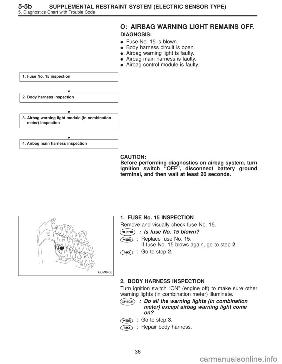
O: AIRBAG WARNING LIGHT REMAINS OFF.
DIAGNOSIS:
�Fuse No. 15 is blown.
�Body harness circuit is open.
�Airbag warning light is faulty.
�Airbag main harness is faulty.
�Airbag control module is faulty.
1. Fuse No. 15 inspection
2. Body harness inspection
3. Airbag warning light module (in combination
meter) inspection
4. Airbag main harness inspection
CAUTION:
Before performing diagnostics on airbag system, turn
ignition switch“OFF”, disconnect battery ground
terminal, and then wait at least 20 seconds.
G5M0460
1. FUSE No. 15 INSPECTION
Remove and visually check fuse No. 15.
: Is fuse No. 15 blown?
: Replace fuse No. 15.
If fuse No. 15 blows again, go to step2.
: Go to step2.
2. BODY HARNESS INSPECTION
Turn ignition switch“ON”(engine off) to make sure other
warning lights (in combination meter) illuminate.
: Do all the warning lights (in combination
meter) except airbag warning light come
on?
: Go to step3.
: Repair body harness.
�
�
�
36
5-5bSUPPLEMENTAL RESTRAINT SYSTEM (ELECTRIC SENSOR TYPE)
5. Diagnostics Chart with Trouble Code
Page 3159 of 3342
B6M0180
1. CHECK CRUISE CONTROL MAIN SWITCH.
1) Remove cruise control main switch.
2) Measure resistance between cruise control main switch
terminals.
Terminals / Specified resistance:
No. 1—No. 6 / Approx. 50Ω
B6M0528A
B6M0531A
2. CHECK CIRCUIT BETWEEN CRUISE CONTROL
MODULE AND CRUISE CONTROL MAIN SWITCH
INDICATOR LIGHT.
1) Turn the ignition switch to ON.
2) Turn cruise control main switch to ON.
3) Measure voltage between cruise control main switch
connector and the body.
Connector & terminal / Specified voltage:
(i19) No. 1—Body / 10 V, or more
4) Turn the ignition switch and cruise control main switch
to OFF.
5) Remove the connector from the cruise control main
switch.
6) Measure resistance of ground circuit between the
cruise control main switch connector and body.
Connector & terminal / Specified resistance:
(i19) No. 6—Body / 10Ω, max.
13
6-2BODY ELECTRICAL SYSTEM
7. Diagnostics Chart for Power Line
Page 3161 of 3342
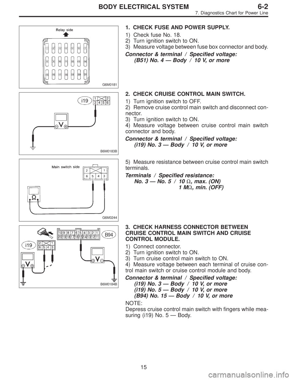
G6M0181
1. CHECK FUSE AND POWER SUPPLY.
1) Check fuse No. 18.
2) Turn ignition switch to ON.
3) Measure voltage between fuse box connector and body.
Connector & terminal / Specified voltage:
(B51) No. 4—Body / 10 V, or more
B6M0183B
2. CHECK CRUISE CONTROL MAIN SWITCH.
1) Turn ignition switch to OFF.
2) Remove cruise control main switch and disconnect con-
nector.
3) Turn ignition switch to ON.
4) Measure voltage between cruise control main switch
connector and body.
Connector & terminal / Specified voltage:
(i19) No. 3—Body / 10 V, or more
G6M0244
5) Measure resistance between cruise control main switch
terminals.
Terminals / Specified resistance:
No. 3—No. 5 / 10Ω, max. (ON)
1MΩ, min. (OFF)
B6M0184B
3. CHECK HARNESS CONNECTOR BETWEEN
CRUISE CONTROL MAIN SWITCH AND CRUISE
CONTROL MODULE.
1) Connect connector.
2) Turn ignition switch to ON.
3) Turn cruise control main switch to ON.
4) Measure voltage between each terminal of cruise con-
trol main switch or cruise control module and body.
Connector & terminal / Specified voltage:
(i19) No. 3—Body / 10 V, or more
(i19) No. 5—Body / 10 V, or more
(B94) No. 15—Body / 10 V, or more
NOTE:
Depress cruise control main switch with fingers while mea-
suring (i19) No. 5—Body.
15
6-2BODY ELECTRICAL SYSTEM
7. Diagnostics Chart for Power Line
Page 3166 of 3342
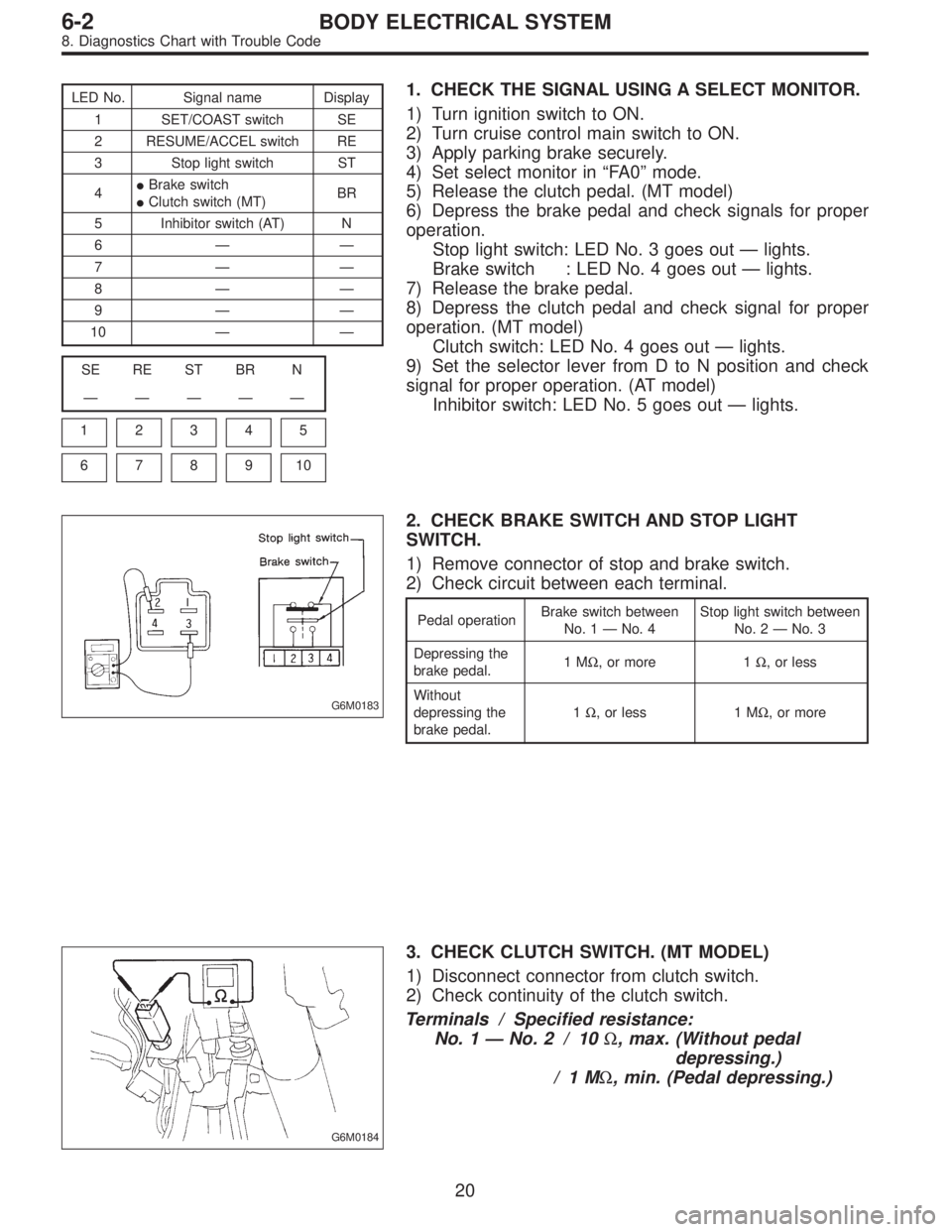
LED No. Signal name Display
1 SET/COAST switch SE
2 RESUME/ACCEL switch RE
3 Stop light switch ST
4�Brake switch
�Clutch switch (MT)BR
5 Inhibitor switch (AT) N
6——
7——
8——
9——
10——
SE RE ST BR N
—————
1
2345
678910
1. CHECK THE SIGNAL USING A SELECT MONITOR.
1) Turn ignition switch to ON.
2) Turn cruise control main switch to ON.
3) Apply parking brake securely.
4) Set select monitor in“FA 0”mode.
5) Release the clutch pedal. (MT model)
6) Depress the brake pedal and check signals for proper
operation.
Stop light switch: LED No. 3 goes out—lights.
Brake switch : LED No. 4 goes out—lights.
7) Release the brake pedal.
8) Depress the clutch pedal and check signal for proper
operation. (MT model)
Clutch switch: LED No. 4 goes out—lights.
9) Set the selector lever from D to N position and check
signal for proper operation. (AT model)
Inhibitor switch: LED No. 5 goes out—lights.
G6M0183
2. CHECK BRAKE SWITCH AND STOP LIGHT
SWITCH.
1) Remove connector of stop and brake switch.
2) Check circuit between each terminal.
Pedal operationBrake switch between
No. 1—No. 4Stop light switch between
No. 2—No. 3
Depressing the
brake pedal.1MΩ,ormore 1Ω, or less
Without
depressing the
brake pedal.1Ω, or less 1 MΩ,ormore
G6M0184
3. CHECK CLUTCH SWITCH. (MT MODEL)
1) Disconnect connector from clutch switch.
2) Check continuity of the clutch switch.
Terminals / Specified resistance:
No. 1—No. 2 / 10Ω, max. (Without pedal
depressing.)
/1MΩ, min. (Pedal depressing.)
20
6-2BODY ELECTRICAL SYSTEM
8. Diagnostics Chart with Trouble Code
Page 3170 of 3342
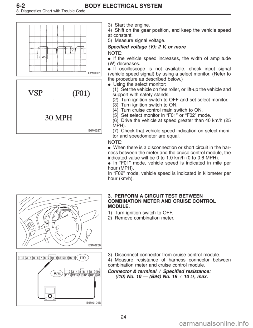
G2M0931
B6M0287
3) Start the engine.
4) Shift on the gear position, and keep the vehicle speed
at constant.
5) Measure signal voltage.
Specified voltage (V): 2 V, or more
NOTE:
�If the vehicle speed increases, the width of amplitude
(W) decreases.
�If oscilloscope is not available, check input signal
(vehicle speed signal) by using a select monitor. (Refer to
the procedure as described below.)
�Using the select monitor:
(1) Set the vehicle on free roller, or lift-up the vehicle and
support with safety stands.
(2) Turn ignition switch to OFF and set select monitor.
(3) Turn ignition switch to ON.
(4) Turn cruise control main switch to ON.
(5) Set select monitor in“F01”or“F02”mode.
(6) Drive the vehicle at speed greater than 40 km/h (25
MPH).
(7) Check that vehicle speed indication on select moni-
tor and speedometer are equal.
NOTE:
�When there is a disconnection or short circuit in the har-
ness between the meter and the cruise control module, the
indicated value will be 0 to 1.0 km/h (0 to 0.6 MPH).
�In“F01”mode, vehicle speed is indicated in mile per
hour (MPH).
In“F02”mode, vehicle speed is indicated in kilometer per
hour (km/h).
B3M0250
3. PERFORM A CIRCUIT TEST BETWEEN
COMBINATION METER AND CRUISE CONTROL
MODULE.
1) Turn ignition switch to OFF.
2) Remove combination meter.
B6M0194B
3) Disconnect connector from cruise control module.
4) Measure resistance of harness connector between
combination meter and cruise control module.
Connector & terminal / Specified resistance:
(i10) No. 10—(B94) No. 19 / 10Ω, max.
24
6-2BODY ELECTRICAL SYSTEM
8. Diagnostics Chart with Trouble Code
