Page 3178 of 3342
B6M0243
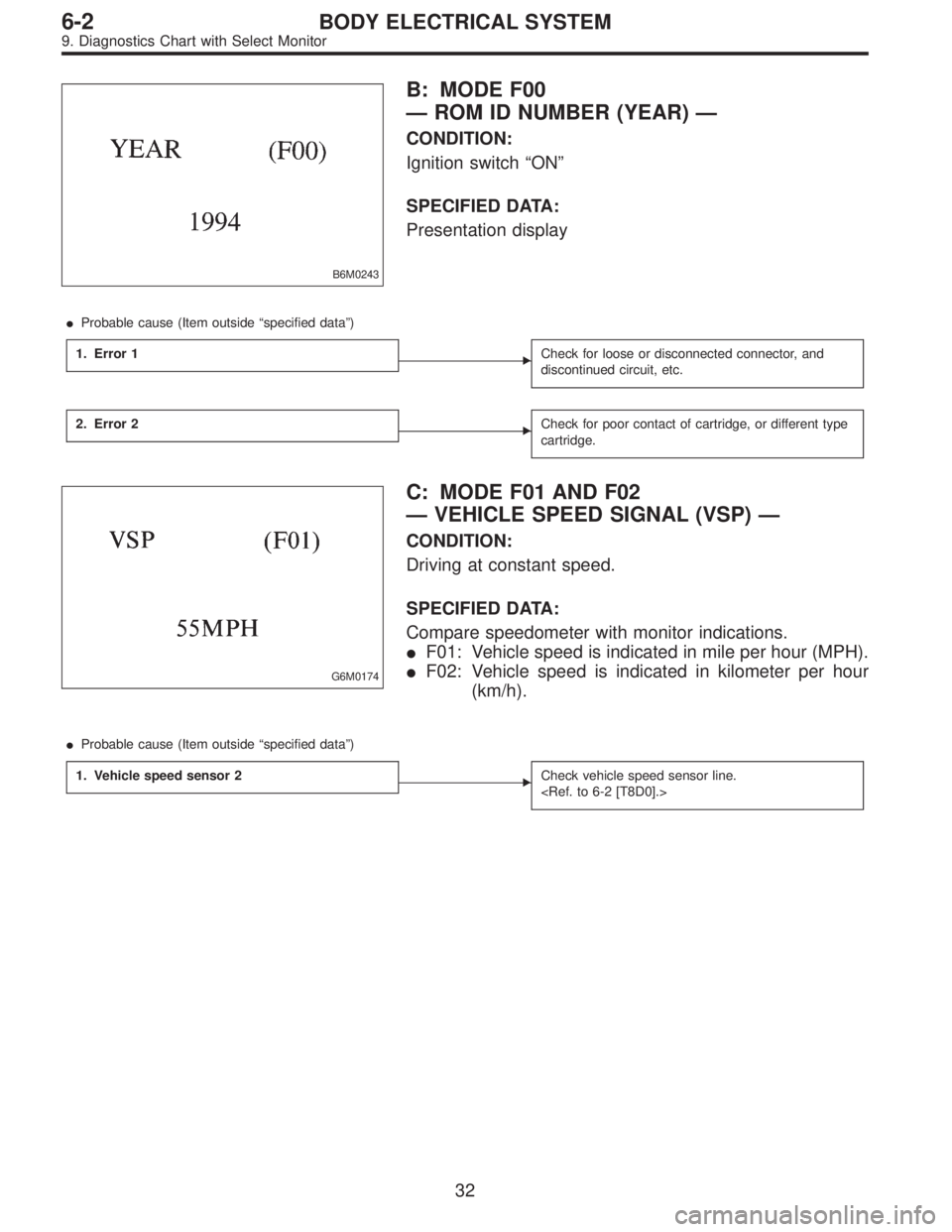
B: MODE F00
—ROM ID NUMBER (YEAR)—
CONDITION:
Ignition switch“ON”
SPECIFIED DATA:
Presentation display
�Probable cause (Item outside“specified data”)
1. Error 1
�Check for loose or disconnected connector, and
discontinued circuit, etc.
2. Error 2�Check for poor contact of cartridge, or different type
cartridge.
G6M0174
C: MODE F01 AND F02
—VEHICLE SPEED SIGNAL (VSP)—
CONDITION:
Driving at constant speed.
SPECIFIED DATA:
Compare speedometer with monitor indications.
�F01: Vehicle speed is indicated in mile per hour (MPH).
�F02: Vehicle speed is indicated in kilometer per hour
(km/h).
�Probable cause (Item outside“specified data”)
1. Vehicle speed sensor 2
�Check vehicle speed sensor line.
32
6-2BODY ELECTRICAL SYSTEM
9. Diagnostics Chart with Select Monitor
Page 3191 of 3342
G6M0213
5) Some connectors are provided with a lock. One type of
such a connector is disconnected by pushing the lock, and
the other, by moving the lock up. In either type the lock
shape must be identified before attempting to disconnect
the connector.
To connect, insert the connector until it snaps and confirm
that it is tightly connected.
G6M0214
6) When checking continuity between connector terminals,
or measuring voltage across the terminal and ground,
always contact tester probe(s) on terminals from the wiring
connection side. If the probe is too thick to gain access to
the terminal, use“mini”test leads.
To check water-proof connectors (which are not accessible
from the wiring side), contact test probes on the terminal
side being careful not to bend or damage the terminals.
7) Sensors, relays, electrical unit, etc., are sensitive to
strong impacts.
Handle them with care so that they are not dropped or
mishandled.
12
6-3WIRING DIAGRAM
3. Working Precautions
Page 3289 of 3342
![SUBARU LEGACY 1997 Service Repair Manual 7. Electrical Unit Location
Electrical unit Refer to;
A.B.S. control module 4-4a [T300]
A.B.S. G sensor (MT) 4-4a [T300]
A/C compressor relay�
7
A/C fuse�11
A/C main fan relay 1�10
A/C main fan relay](/manual-img/17/57434/w960_57434-3288.png "SUBARU LEGACY 1997 Service Repair Manual 7. Electrical Unit Location
Electrical unit Refer to;
A.B.S. control module 4-4a [T300]
A.B.S. G sensor (MT) 4-4a [T300]
A/C compressor relay�
7
A/C fuse�11
A/C main fan relay 1�10
A/C main fan relay")
7. Electrical Unit Location
Electrical unit Refer to;
A.B.S. control module 4-4a [T300]
A.B.S. G sensor (MT) 4-4a [T300]
A/C compressor relay�
7
A/C fuse�11
A/C main fan relay 1�10
A/C main fan relay 2�8
A/C pressure switch�2
A/C sub fan relay 2�9
ATF temperature sensor 2-7 [T2B1]
Blower motor resistor�
26
Blower relay�13
Camshaft position sensor 2-7 [T2A2]
Check connector�
25
Clutch switch (MT) 6-2 [T300]
Crankshaft position sensor 2-7 [T2A2]
Cruise control module 6-2 [T300]
Cruise control pump 6-2 [T300]
Data link connector (for OBD-II G.S.T.) 2-7 [T2A1]
Data link connector (for S.S.M.) 2-7 [T2A1]
Diagnosis connector 4-4a [T300]
Diagnosis terminal (Ground) 4-4a [T300]
Door lock timer�
27
Engine control module 2-7 [T2A1]
Engine coolant temperature sensor 2-7 [T2A2]
Engine hood switch (Security) 6-2 [K6A0]
Evaporator thermoswitch�
29
F/B�15
FRESH/RECIRC actuator�28
Fuel pump relay 2-7 [T2A3]
Fuel gauge module�
31
Fuel gauge sub module (AWD)�32
FWD switch (AT)�1
Headlight alarm relay (Security) 6-2 [K6A0]
Headlight relay LH�
5
Headlight relay RH�6
Horn relay�14
Electrical unit Refer to;
Hydraulic unit (A.B.S.) 4-4a [T300]
Ignition coil 2-7 [T2A3]
Ignitor 2-7 [T2A3]
Idle air control solenoid valve 2-7 [T2A3]
Illumination control module�
21
Inhibitor switch 6-2 [T300]
Knock sensor 2-7 [T2A2]
Main fan relay�
19
Main relay 2-7 [T2A3]
Mass air flow sensor 2-7 [T2A2]
Mode actuator�
12
M/B�4
Oil pressure switch�3
Oxygen sensor 2-7 [T2A2]
Pedal stroke sensor (T.C.S.) 4-4b [T300]
Power window and sunroof relay�
24
Power window circuit breaker�23
Purge control solenoid valve 2-7 [T2A3]
Rear defogger relay�
17
Seat belt timer�20
Security control module 6-2 [K6A0]
Shift lock control module�
22
Starter interrupt relay (Security) 6-2 [K6A0]
Stop & brake switch (With cruise con-
trol)6-2 [T300]
Sunroof control module�
30
Tail and illumination relay�18
T.C.S. control module 4-4b [T300]
T.C.S. motor relay 4-4b [T300]
T.C.S. valve relay 4-4b [T300]
Throttle position sensor 2-7 [T2A2]
Test mode connector 2-7 [T2A1]
Transmission control module 2-7 [T2B1]
Turn & hazard module�
16
Vehicle speed sensor 1 2-7 [T2B1]
Vehicle speed sensor 2 2-7 [T2B1]
11 0
6-3WIRING DIAGRAM
7. Electrical Unit Location
Page 3295 of 3342
8. Electrical Wiring Harness and
Ground Point
B6M0267A
�1Front wiring harness
�
2Engine wiring harness
�
3Room light cord
�
4Bulkhead wiring harness
�
5Instrument panel wiring harness
�
6Front door cord RH
�
7Rear door cord RH
�
8Rear wiring harness
�
9Trunk lid cord (Sedan)�
10Rear defogger ground cord (Sedan)
�
11Fuel tank cord
�
12Rear door cord LH
�
13Front door cord LH
�
14Sunroof cord
�
15Floor wiring harness
�
16Transmission cord
�
17Rear gate cord (Wagon)
�
18Rear oxygen sensor cord
11 6
6-3WIRING DIAGRAM
8. Electrical Wiring Harness and Ground Point
Page 3301 of 3342

Connector Connecting to
No. Pole Color Area No. Name
B1 2 * B-2 Pressure source switching solenoid
B2 3 Black B-2 Pressure sensor
B3 5 Gray B-2 Mass air flow sensor
B4 2 Gray B-2 AT dropping resistor
B5 2 Gray B-2 Resistor (Daytime running light)
B62 Gray B-2 ABS front sensor RH
2 Brown B-2 ABS front sensor RH (Outback with step roof)
B7 4 * B-2 Cruise control pump
B8 6 * A-2 Front wiper motor
B9 2 Black A-2 FWD switch (AT)
B10 2 Brown B-2 A/C pressure switch
B11 16 Gray B-3 T4
Transmission (AT)
B12 12 Gray B-2 T3
B13 6 Gray B-3 Ignitor
B14 1 Black B-3 Starter (Magnet)
B152 Gray B-3 ABS front sensor LH
2 Brown B-3 ABS front sensor LH (Outback with step roof)
B16 2 Gray B-3 Brake fluid level switch
B17 2 Black B-2 Vehicle speed sensor
B18 3 Dark gray B-2 Front oxygen sensor
B194 * B-2 T5 Rear oxygen sensor cord (Other models)
4 * B-2 Rear oxygen sensor (California model)
B20 6 Light gray B-2 E1
Engine wiring harness B21 12 Light gray B-2 E2
B22 16 Light gray B-2 E3
B24 2 Gray B-2 T1 Back-up light switch (MT)
B25 2 Brown B-2 T2 Neutral position switch (MT)
*: Non-colored
122
6-3WIRING DIAGRAM
8. Electrical Wiring Harness and Ground Point
Page 3303 of 3342
Connector Connecting to
No. Pole Color Area No. Name
B1 2 Brown B-2 Pressure sources switching solenoid
B2 3 Black B-2 Pressure sensor
B3 5 Gray B-2 Mass air flow sensor
B4 2 Gray B-2 AT dropping resistor
B7 4 Gray B-3 Cruise control pump
B8 6 * B-3 Front wiper motor
B9 2 Black A-2 FWD switch
B11 16 Gray B-3 T4
Transmission
B12 12 Gray B-2 T3
B13 6 Gray B-3 Ignitor
B14 1 Black B-3 Starter (Magnet)
B16 2 Gray B-2 Brake fluid level switch
B17 2 Black B-3 Vehicle speed sensor
B18 3 Dark gray B-2 Front oxygen sensor
B194 * B-2 T5 Rear oxygen sensor cord (Other models)
4 * B-2 Rear oxygen sensor (California model)
B20 6 Light gray B-2 E1
Engine wiring harness B21 12 Light gray B-2 E2
B22 16 Light gray B-2 E3
B26 2 Black B-3
M/B B27 3 * B-3
B28 1 Brown B-3
B29 2 * B-2 Rear washer motor
B110 2 Green B-3 Front washer motor
*: Non-colored
124
6-3WIRING DIAGRAM
8. Electrical Wiring Harness and Ground Point
Page 3305 of 3342

Connector Connecting to
No. Pole Color Area No. Name
E1 6 * A-3 B20
Bulkhead wiring harness E2 12 Gray A-3 B21
E3 16 Gray A-3 B22
E4 2 Blue A-2 Purge control solenoid valve
E5 2 Light gray A-2 Injector #1
E6 2 Dark gray A-3 Injector #3
E7 3 Gray A-3 Idle air control solenoid valve
E8 2 Brown B-3 Engine coolant temperature sensor
E9 1 * B-3 Thermometer
E10 2 Gray B-3 Crankshaft position sensor
E11 1 * B-3 Oil pressure switch
E12 3 Gray A-3 Ignition coil
E13 3 Brown A-3 Throttle position sensor
E14 2 Gray B-3 Knock sensor
E15 2 Dark gray B-4 Camshaft position sensor
E16 2 Light gray B-4 Injector #2
E17 2 Dark gray B-4 Injector #4
E18 2 Brown B-3 EGR solenoid (AT)
*: Non-colored
Connector Connecting to
No. Pole Color Area No. Name
T1 2 Gray C-1 B24
Bulkhead wiring harness (MT)
T2 2 Brown C-1 B25
T3 12 Gray D-3 B12
Bulkhead wiring harness (AT)
T4 16 Gray D-3 B11
T5 4 Gray C-1/C-3 B19 Bulkhead wiring harness
T6 4 Gray D-2/D-4 Rear oxygen sensor
T7 12 * C-4 Inhibitor switch (AT)
*: Non-colored
126
6-3WIRING DIAGRAM
8. Electrical Wiring Harness and Ground Point
Page 3307 of 3342
 harness
B32 3 Black C-1 Turn & hazard module
B33 4 Brown B-1 Diode (Brake flui")
Connector Connecting to
No. Pole Color Area No. Name
B30 24 * C-1 D1 Front door cord LH
B31 7 Yellow C-1 AB1 SRS (Airbag) harness
B32 3 Black C-1 Turn & hazard module
B33 4 Brown B-1 Diode (Brake fluid level)
B352 Black B-1 Diode (Without step light)
4 Brown B-1 Diode (With step light)
B36 22 Black C-1 i1
Instrument panel wiring
harness B37 22 * C-1 i2
B38 22 Brown C-1 i3
B39 20 Blue C-1 i4
B40 16 Gray C-2 OBD-II service connector
B41 2 * C-2 Power window circuit breaker
B42 4 * C-2Power window and sunroof
relay
B43 6 Black C-2 Illumination control module
B44 8 * C-2 Seat belt timer
B45 4 * B-1 R53 Sunroof cord
B46 4 Green B-1 Fuel pump relay
B47 6 Brown B-1 Main relay
B48 4 Blue B-1 Front fog light relay
B49 3 Black B-1 Horn relay
B50 4 * B-1 Blower relay
B51 11 Gray B-1
F/B
B52 12 Gray B-1
B53 4 * B-2 Shield joint connector (AT)
B54 12 Black B-2
Transmission control module B55 16 Black B-2
B56 20 Black B-2
B57 12 Black B-2 Shift-lock control module
B58 5 Black B-1Headlight alarm relay
(Security)
B59 5 Black B-1 Interrupt relay (Security)
B60 4 * B-2Shield joint connector
(With TCS model)
B61 8 * B-2 F44
Front wiring harness
B62 20 * B-1 F45
B63 40 Gray B-1 P10Floor harness
(With TCS model)
B64 2 Black B-2 Stop light switch
B65 4 Black B-2Stop & brake switch
(With cruise control)
B66 3 Black B-2 Pedal stroke sensor (TCS)
B67 4 Black B-2 Pedal stroke switch (TCS)
B68 5 Black B-3 Slip ring
B69 11 Black B-3
Combination switch B70 9 * B-3
B71 8 * B-3
B72 6 Black B-3 Ignition switch
B73 2 Black B-3 Key lock solenoid (AT)
B74 2 Black B-3 Key warning switchConnector Connecting to
No. Pole Color Area No. Name
B75 2 Green C-2 B76
Test mode connector
B76 2 Green C-3 B75
B77 10 Brown B-2 Mode actuator
B78 9 Yellow C-2 Data link connector
B79 14 Gray C-2 Check connector
B80 4 Blue B-2 i20Instrument panel wiring
harness
B81 1 x 2 * C-2 Diagnosis terminal (Ground)
B82 6 Black C-2 Diagnosis connector
B83 4 * C-3 Shield joint connector (E/G)
B84 96Light
blueB-3 Engine control module
B86 4 * B-3 Blower motor resistor
B87 2 * B-3 Blower motor
B88 3 Black B-3 Evaporator thermoswitch
B89 2 Black B-3 Diode (Security)
B90 4 * B-4 R50 Room light cord
B91 4 * B-4 FRESH/RECIRC actuator
B92 8 * B-4 Door lock timer
B93 16 Black B-4 Security control module
B94 20 Black B-4 Cruise control module
B95 2 Black B-4 Diode (Daytime running light)
B96 10 * B-4Daytime running light control
module
B97 8 * B-4 R1 Rear wiring harness
B9820 * B-4 R2Rear wiring harness
(Other models)
24 Black B-4 R2Rear wiring harness
(2200 cc engine AWD except
Taiwan model)
B99 24 * B-4 R3 Rear wiring harness
B100 20 Blue B-4 F2Front wiring harness
(With ABS model)
B101 24 * B-4 D11 Front door cord RH
B102 5 Black B-4 Daytime running light relay
B103 4 Blue B-4High-beam relay
(Daytime running light)
B104 4 Pink B-4 Rear power supply relay
B105 4 Blue B-1 Starter interlock relay (MT)
B106 2 * B-1 Clutch switch (MT)
B107 2 Blue B-1 Clutch switch (Cruise control)
B108 2 Black B-2 F46Front wiring harness
(Outback)
B109 4 Black C-1 Fuse holder (Outback)
B112 2 Black B-1 Diode (Front fog light)
B113 2 * C-1 D50 Front door cord LH
*: Non-colored
Connector Connecting to
No. Pole Color Area No. Name
S1 3 White D-3 Cruise control sub switch
128
6-3WIRING DIAGRAM
8. Electrical Wiring Harness and Ground Point
 Some connectors are provided with a lock. One type of
such a connector is disconnected by pushing the lock, and
the other, by moving the lock up. In either type the lock
shape must be ident")