Page 1185 of 3342
 5.3 (17.4) 5.6 (18.4)
Steering angle (Inside-Outside) 37.6°—32.6°34.4°—30.2°
S")
1. Steering System
A: SPECIFICATIONS
Except OUTBACK model OUTBACK model
Whole systemMinimum turning radius m (ft) 5.3 (17.4) 5.6 (18.4)
Steering angle (Inside-Outside) 37.6°—32.6°34.4°—30.2°
Steering wheel diameter mm (in) 385 (15.16)
Overall gear ratio (Turns, lock to lock) 16.5 (3.2) 19 (3.4)
GearboxType Rack and pinion, Integral
Backlash 0 (Automatically adjustable)
Valve (Power steering system) Rotary valve
Pump (Power steering
system)Type Vane pump
Oil tank Installed on pump
Output cm
3(cu in)/rev. 7.2 (0.439)
Relief pressure kPa (kg/cm
2, psi) 7,355 (75, 1,067)
Hydraulic fluid controlDropping in response to increased engine
revolutions
Hydraulic fluid�(US qt, Imp qt)1,000 rpm: 7 (7.4, 6.2)
3,000 rpm: 5 (5.3, 4.4)
Range of revolution rpm 500—7,500
Revolving direction Clockwise
Working fluid (Power
steering system)Name ATF DEXRON II, IIE or III
Capacity Oil tank�(US qt, Imp qt)
Total0.35 (0.4, 0.3)
0.7 (0.7, 0.6)
2
4-3SPECIFICATIONS AND SERVICE DATA
1. Steering System
Page 1186 of 3342
 17 (0.67)
Turning angleInner tire & wheel 37.6°34.4°
Outer tire & wheel 32.6°30.2°
Steering shaftClearance betwe")
B: SERVICE DATA
Except OUTBACK model OUTBACK model
Steering wheel Free play mm (in) 17 (0.67)
Turning angleInner tire & wheel 37.6°34.4°
Outer tire & wheel 32.6°30.2°
Steering shaftClearance between steering
wheel and column cover
mm (in)3.0 (0.118)
Steering gearbox
(Power steering system)Sliding resistance N (kg, lb) 240.3 (24.5, 54.0) or less
Rack shaft play in radial direc-
tion
mm (in)0.15 (0.0059) or less
Right-turn steering Horizontal movement: 0.3 (0.012) or less
Left-turn steering Vertical movement: 0.15 (0.0059) or less
Input shaft play mm (in)
In radial direction 0.18 (0.0071) or less
In axial direction 0.1 (0.004) or less
Turning resistance N (kg, lb)Within 30 mm (1.18 in) from rack center in straight ahead
position: Less than 11.18 (1.14, 2.51)
Maximum allowable value: 12.7 (1.3, 2.9)
Oil pump (Power steering sys-
tem)Pulley shaft mm (in)
Radial play 0.4 (0.016) or less
Axial play 0.9 (0.035) or less
Pulley
Ditch deflection mm (in)
Resistance to rotation
N (kg, lb)1.0 (0.039) or less
9.22 (0.94, 2.07) or less
Regular pressure
kPa (kg/cm
2, psi)981 (10, 142) or less
Relief pressure
kPa (kg/cm
2, psi)7,355 (75, 1,067)
Steering wheel effort
(Power steering system)At standstill with engine
idling on a concrete road
N (kg, lb)31.4 (3.2, 7.1) or less
At standstill with engine
stalled on a concrete road
N (kg, lb)147 (15, 33) or less
C: RECOMMENDED POWER STEERING
FLUID
Recommended power steering fluid Manufacturer
ATF DEXRON II, ATF DEXRON IIE or ATF
DEXRON IIIB.P.
CALTEX
CASTROL
MOBIL
SHELL
TEXACO
3
4-3SPECIFICATIONS AND SERVICE DATA
1. Steering System
Page 1200 of 3342
A: REMOVAL
1) Disconnect battery minus terminal.
2) Loosen front wheel nut.
3) Lift vehicle and remove front wheels.
4) Remove front exhaust pipe assembly.
WARNING:
Be careful, exhaust pipe is hot.
G4M0097
5) Using a puller, remove tie-rod end from knuckle arm
after pulling off cotter pin and removing castle nut.
G4M0098
6) Remove jack-up plate and front stabilizer.
G4M0099
7) Remove one pipe joint at the center of gearbox, and
connect vinyl hose to pipe and joint. Discharge fluid by
turning steering wheel fully clockwise and counterclock-
wise. Discharge fluid similarly from the other pipe.
G4M0086
8) Remove lower side bolt of universal joint, then remove
upper side bolt and lift the joint upward.
NOTE:
Place a mark on the joint and mating serration so that they
can be re-installed at the original position.
16
4-3SERVICE PROCEDURE
3. Steering Gearbox (Power Steering System) [LHD model]
Page 1210 of 3342
 How to install the joint.
(1) Push the long yoke of the joint, all the way into the
serrated portion of the steering shaft, setting the bolt
hole in the cutout.
(2) Then pull the short yoke all way")
3) How to install the joint.
(1) Push the long yoke of the joint, all the way into the
serrated portion of the steering shaft, setting the bolt
hole in the cutout.
(2) Then pull the short yoke all way out of the serrated
portion of the gearbox, setting the bolt hole in the cut-
out.
(3) Insert the bolt through the short yoke, pull the joint
and confirm that the bolt is on cutout of the gearbox.
G4M0086
(4) Fasten the short yoke side with a spring washer
and bolt, then fasten the long yoke side.
Tightening torque:
24±3 N⋅m (2.4±0.3 kg-m, 17.4±2.2 ft-lb)
G4M0097
4) Connect tie-rod end and knuckle arm, and tighten with
castle nut. Fit cotter pin into the nut and bend the pin to
lock.
Castle nut tightening torque:
Tighten to 27.0±2.5 N⋅m (2.75±0.25 kg-m,
19.9±1.8 ft-lb), and tighten further within 60°until
cotter pin hole is aligned with a slot in the nut.
CAUTION:
When connecting, do not hit cap at the bottom of tie-
rod end with hammer.
5) Install front stabilizer to vehicle.
6) Install front exhaust pipe assembly.
7) Install tires.
8) Tighten wheel nuts to the specified torque.
Tightening torque:
88±10 N⋅m (9.0±1.0 kg-m, 65±7 ft-lb)
9) Connect ground cable to battery.
10) Pour fluid into oil tank, and bleed air.
[W9A0].>
11) Check for fluid leaks.
12) Install jack-up plate.
WARNING:
Be careful, exhaust manifold is hot.
13) Lower vehicle.
14) Check fluid level in oil tank.
26
4-3SERVICE PROCEDURE
3. Steering Gearbox (Power Steering System) [LHD model]
Page 1214 of 3342
 Disconnect battery negative terminal.
2) Disconnect both oxygen sensor and exhaust gas tem-
perature warning sensor connectors from front exhaust
pipe assembly.
WARNING:
Be careful as ex")
A: REMOVAL
1) Disconnect battery negative terminal.
2) Disconnect both oxygen sensor and exhaust gas tem-
perature warning sensor connectors from front exhaust
pipe assembly.
WARNING:
Be careful as exhaust pipe is hot.
3) Raise vehicle with a jack and remove front wheel.
4) Disconnect front exhaust pipe assembly.
G4M0097
5) Remove cotter pin and castle nut. Using a puller,
remove tie-rod end from knuckle arm.
G4M0098
6) Remove jack-up plate and stabilizer.
G4M0786
7) Disconnect one pipe joint A from center of gearbox
assembly, and connect a vinyl hose to it. While turning
steering wheel to the left and right, drain fluid through the
hose. Similarly, drain fluid from the other pipe joint B.
G4M0787
8) Remove lower and upper bolts from universal joint, and
remove universal joint in the upward direction.
NOTE:
Scribe alignment marks on universal joint so that it can be
reassembled at the original serration.
30
4-3SERVICE PROCEDURE
4. Steering Gearbox (Power Steering System) [RHD model]
Page 1230 of 3342

G4M0152
�Installation
Force-fit oil seal and back-up washer using ST.
ST 927650000 INSTALLER
CAUTION:
Be careful not to damage or scratch cylinder inner
wall.
NOTE:
�Apply ATF DEXRON II to oil seal.
�Pay special attention not to install back-up washer and
oil seal in wrong direction.
�Push oil seal until the stepped portion of A contacts end
face of B.
B4M0134A
D: ASSEMBLY
1. RACK ASSEMBLY
1) Fixing rack housing
Fix rack housing in vice using ST.
ST 926200000 STAND
CAUTION:
�When fixing rack housing in vice, be sure to use this
special tool. Do not fix rack housing in vice using pad
such as aluminum plates, etc.
�When using old rack housing, be sure to clean and
remove rust before assembling. Check pinion housing
bushing carefully.
G4M0154
2) Fit ST over toothed portion of rack assembly, and check
for binding or unsmooth insertion. If any deformation is
noted on flats at the end of rack, shape by using file, and
wash with cleaning fluid.
3) Apply genuine grease to teeth of thoroughly washed
rack assembly, and fit ST over the toothed portion.
ST 926390001 COVER & REMOVER
NOTE:
�Be careful not to block air passage with grease. Remove
excessive grease.
46
4-3SERVICE PROCEDURE
5. Control Valve (Power Steering Gearbox) [LHD model]
Page 1236 of 3342
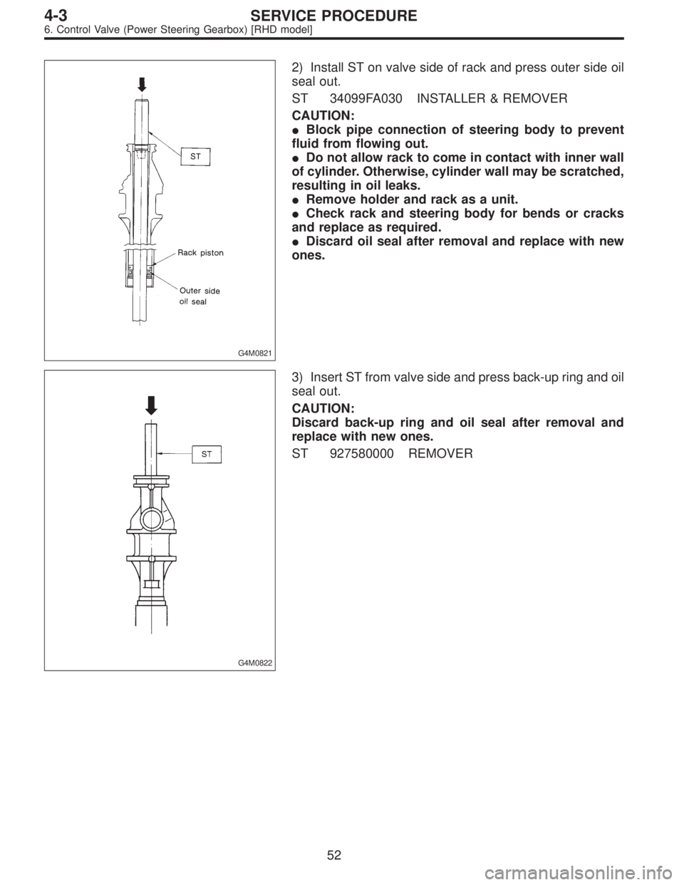
G4M0821
2) Install ST on valve side of rack and press outer side oil
seal out.
ST 34099FA030 INSTALLER & REMOVER
CAUTION:
�Block pipe connection of steering body to prevent
fluid from flowing out.
�Do not allow rack to come in contact with inner wall
of cylinder. Otherwise, cylinder wall may be scratched,
resulting in oil leaks.
�Remove holder and rack as a unit.
�Check rack and steering body for bends or cracks
and replace as required.
�Discard oil seal after removal and replace with new
ones.
G4M0822
3) Insert ST from valve side and press back-up ring and oil
seal out.
CAUTION:
Discard back-up ring and oil seal after removal and
replace with new ones.
ST 927580000 REMOVER
52
4-3SERVICE PROCEDURE
6. Control Valve (Power Steering Gearbox) [RHD model]
Page 1246 of 3342
G4M0098
7. Pipe Assembly (Power Steering
System)
A: REMOVAL
1. LHD MODEL
1) Disconnect battery minus terminal.
G4M0099
2) Lift vehicle and remove jack-up plate.
3) Remove one pipe joint at the center of gearbox, and
connect vinyl hose to pipe and joint. Discharge fluid by
turning steering wheel fully clockwise and counterclock-
wise. Discharge fluid similarly from the other pipe.
CAUTION:
Improper removal and installation of parts often
causes fluid leak trouble. To prevent this, clean the
surrounding portions before disassembly and
reassembly, and pay special attention to keep dirt and
other foreign matter from mating surfaces.
G4M0162
4) Remove clamp E from pipes C and D.
62
4-3SERVICE PROCEDURE
7. Pipe Assembly (Power Steering System)
 Disconnect battery minus terminal.
2) Loosen front wheel nut.
3) Lift vehicle and remove front wheels.
4) Remove front exhaust pipe assembly.
WARNING:
Be careful, exhaust pipe is hot.
G4")

A: REMOVAL
1. LHD MODEL
1) Disconnect battery minus terminal.
G4M0099
2) Lift vehicle and remove jack-up plate.
3) Remove one pipe joint at the center")